Removal Procedure
Tools Required
| • | J 28467-B Universal Engine Support Fixture |
| • | J 28467-90A Engine Support Adapters |
| • | J 37096 Flywheel Holder |
- Disconnect the negative battery cable. Refer to Battery Negative Cable Disconnection and Connection in Engine Electrical.
- Drain the engine coolant from the cooling system. Refer to Cooling System Draining and Filling in Engine Cooling.
- Remove the drive belt tensioner. Refer to Drive Belt Tensioner Replacement .
- Remove the crankshaft balancer. Refer to Crankshaft Balancer Replacement .
- Disconnect the wiring harness connectors from the engine front cover.
- Remove the crankshaft position sensor shield.
- Install the J 28467-90A and the J 28467-B . Refer to Engine Support Fixture .
- Remove the engine mount bracket for oil pan access. Refer to Engine Mount Bracket Replacement .
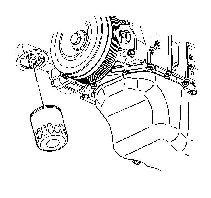
- Lower the oil pan and remove the oil pan-to-engine front cover bolts.
- Remove the oil filter.
- Remove the radiator outlet hose. Refer to Radiator Outlet Hose Replacement in Engine Cooling.
- Remove the water pump pulley. Refer to Water Pump Replacement in Engine Cooling.
- Remove the crankshaft position sensor.
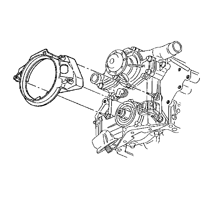
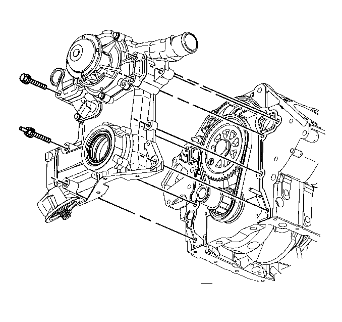
- Remove the engine front cover attaching bolts.
- Remove the engine front cover with the oil filter adapter as one assembly.
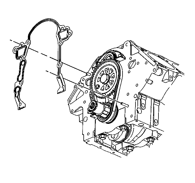
- Remove the engine front cover gasket.
- If replacing the engine front cover, remove the oil filter adapter and pressure relief valve from the engine front cover. Refer to Oil Filter Adapter and Bypass Valve Assembly Replacement .
- If replacing the engine front cover, remove the water pump from the engine front cover. Refer to Water Pump Replacement in Engine Cooling.
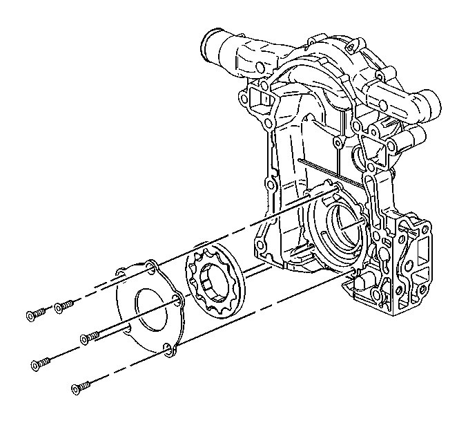
- If replacing the engine front cover, remove the oil pump cover and gear set from the engine front cover. Refer to Oil Pump Cover and Gear Set Removal .
- Inspect the oil pump cover and gear set. Refer to Oil Pump Cleaning and Inspection .
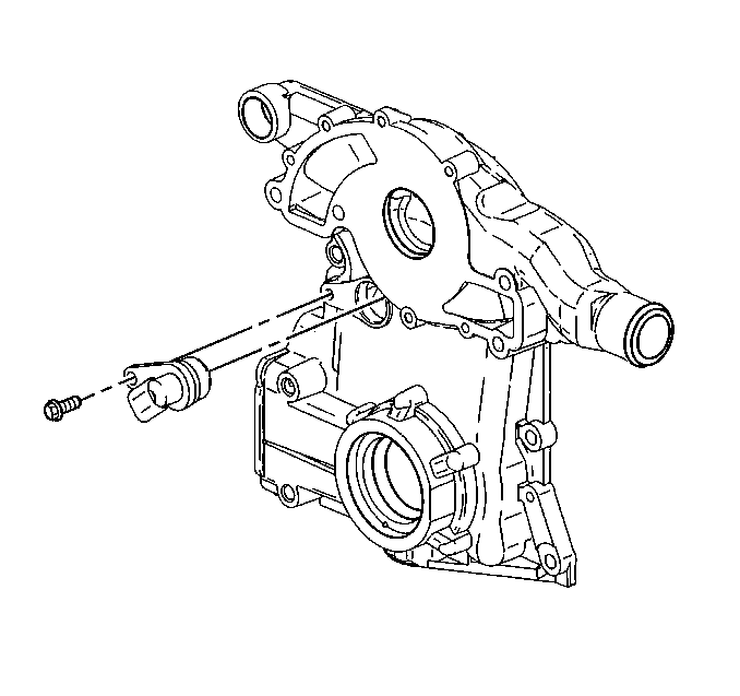
- If replacing the engine front cover, remove the camshaft position sensor from the engine front cover.
- Inspect the timing chain for overall in and out movement. Maximum movement is 25.4 mm (1 in). Refer to Camshaft Timing Chain and Sprocket Cleaning and Inspection .
- Inspect the sprockets for wear.
- Clean the mating surfaces of the front cover and cylinder block.
- Clean the sealing surfaces with degreaser.
Caution: Before servicing any electrical component, the ignition and start switch must be in the OFF or LOCK position and all electrical loads must be OFF, unless instructed otherwise in these procedures. If a tool or equipment could easily come in contact with a live exposed electrical terminal, also disconnect the negative battery cable. Failure to follow these precautions may cause personal injury and/or damage to the vehicle or its components.
Important: The oil pan can be dropped slightly for engine front cover clearance if all pan bolts are loosened and the oil level sensor is removed.
Installation Procedure
Tools Required
J 36660-A Electronic Torque Angle Meter
- If replacing the engine front cover, install the camshaft position sensor to the engine front cover.
- If replacing the engine front cover, install the oil pump cover and gear set to the engine front cover. Refer to Oil Pump Cover and Gear Set Removal .
- If replacing the engine front cover, install the oil filter adapter and pressure relief valve to the engine front cover. Refer to Oil Filter Adapter and Bypass Valve Assembly Replacement .
- If replacing the engine front cover, install the water pump to the engine front cover. Refer to Water Pump Replacement in Engine Cooling.
- Install the new engine front cover seal. Refer to Crankshaft Front Oil Seal Replacement .
- Install the new engine front cover gasket. Make sure that the sealing surfaces are not damaged.
- Apply sealer GM P/N 1052080 or equivalent to the bolt threads.
- Align the cogs on the crankshaft sprocket with the cogs on the oil pump gear set in the engine front cover.
- Install the engine front cover on the engine.
- Install the crankshaft position sensor.
- Install the engine front cover bolts (1-7).
- Inspect the oil pan gasket. Replace if necessary.
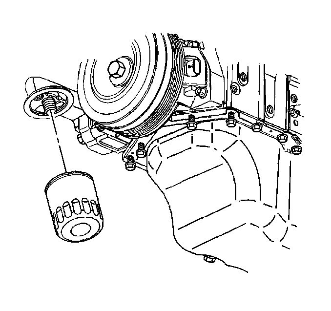
- Install the oil pan-to-engine front cover bolts and the oil pan bolts.
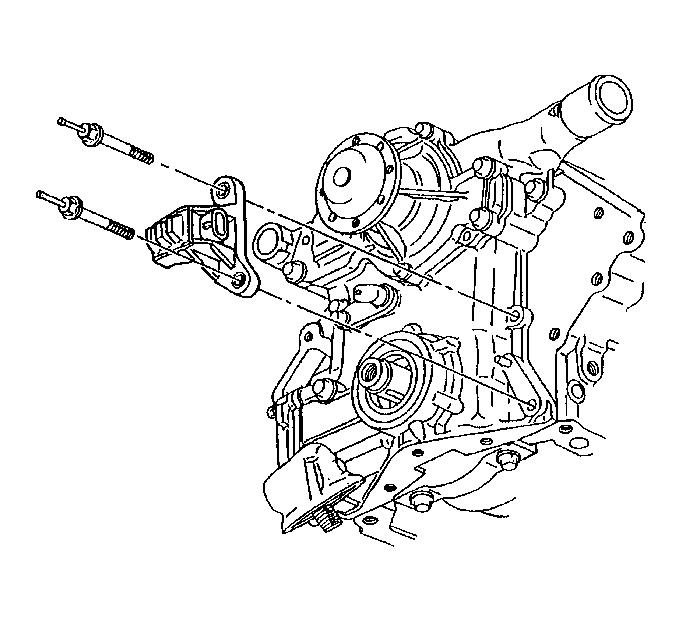
- Install the engine mount bracket.
- Lower the engine.
- Install the engine mount bracket bolts. Refer to Engine Mount Bracket Replacement .
- Remove the J 28467-B and the J 28467-90A .
- Install the water pump pulley. Refer to Water Pump Replacement in Engine Cooling.
- Connect the radiator outlet hose. Refer to Radiator Outlet Hose Replacement in Engine Cooling.
- Install the oil filter. Refer to Engine Oil and Oil Filter Replacement .
- Install the crankshaft position sensor shield.
- Connect the wiring harness connectors to the engine front cover.
- Install the crankshaft balancer. Refer to Crankshaft Balancer Replacement .
- Install the drive belt tensioner. Refer to Drive Belt Tensioner Replacement .
- Fill the cooling system with engine coolant. Refer to Cooling System Draining and Filling in Engine Cooling.
- Fill the crankcase with clean engine oil. Refer to Fluid and Lubricant Recommendations and Approximate Fluid Capacities in Maintenance and Lubrication.
- Connect the negative battery cable. Refer to Battery Negative Cable Disconnection and Connection in Engine Electrical.
- Inspect for proper fluid levels.
- Inspect for leaks.

Notice: Use the correct fastener in the correct location. Replacement fasteners must be the correct part number for that application. Fasteners requiring replacement or fasteners requiring the use of thread locking compound or sealant are identified in the service procedure. Do not use paints, lubricants, or corrosion inhibitors on fasteners or fastener joint surfaces unless specified. These coatings affect fastener torque and joint clamping force and may damage the fastener. Use the correct tightening sequence and specifications when installing fasteners in order to avoid damage to parts and systems.
Tighten
Tighten the camshaft position sensor bolts to 10 N·m (89 lb in).


Tighten
Tighten the crankshaft position sensor studs to 30 N·m
(22 lb ft).
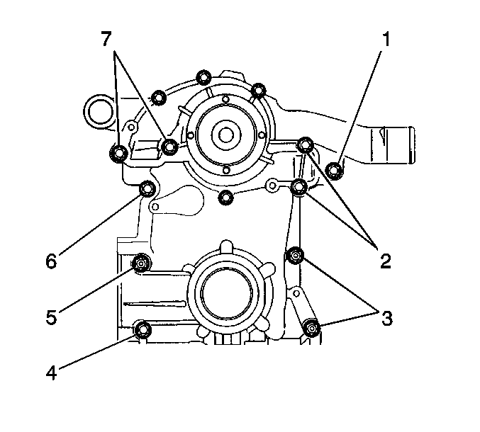
Tighten
Tighten the engine front cover bolts to 20 N·m (15 lb ft).
Use the J 36660-A
in order
to rotate the bolts an additional 40 degrees.
Tighten
Tighten the oil pan-to-engine front cover bolts to 14 N·m
(125 lb in).
