For 1990-2009 cars only
Ignition Switch Assembly - Disassemble - Off Vehicle Floor Shift
Disassembly Procedure
Tools Required
| • | J 41352 Modular Column Holding Fixture |
| • | J 42640 Steering Column Anti Rotation Pin |
- Set the steering column and J 41352 into a vise.
- Install J 42640 into the steering column.
- Place the ignition in the "LOCK" position to center the coil assembly.
- Remove the wire protector from the steering column jacket assembly.
- Remove the wire harness assembly strap (1) from the steering column jacket assembly.
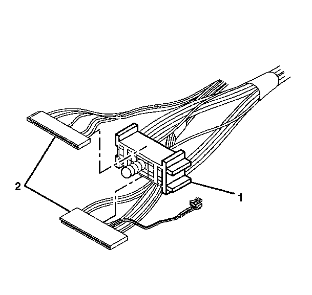
- Slide the pivot and pulse dimmer switch assembly connector (2) out from the bulkhead connector (1).
- Slide the turn signal switch assembly connector (2) out from the bulkhead connector (1).
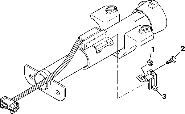
- Remove the 2 washer head screws (2) from the column lock and ignition switch assembly (3).
- Remove the column lock and ignition switch assembly (3) from the ignition switch actuator assembly.
- Remove the column lock and ignition switch assembly (3) from the steering column jacket assembly (1).

Important: The column must be in the center position.
Remove only those components necessary to do the repairs. Check the steering column jacket assembly for accident damage. Refer to Steering Column Accident Damage Inspection - Off Vehicle .

Ignition Switch Assembly - Disassemble - Off Vehicle Column Shift
Disassembly Procedure
- Slide the turn signal switch assembly connector (2) out from the bulkhead connector (1).
- Slide the pivot and pulse dimmer switch assembly connector (2) out from the bulkhead connector (1).
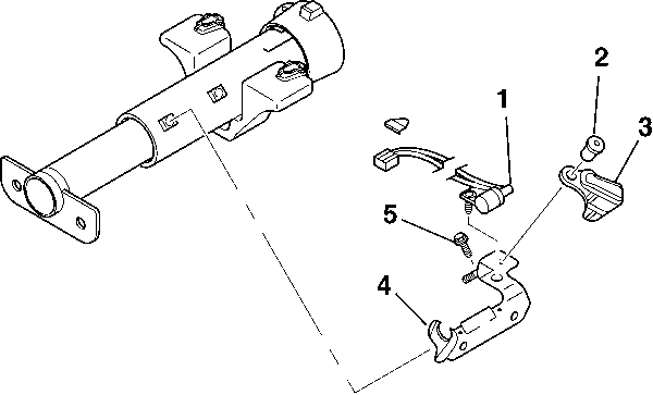
- Remove the following items from the PRNDL adjuster assembly (3):
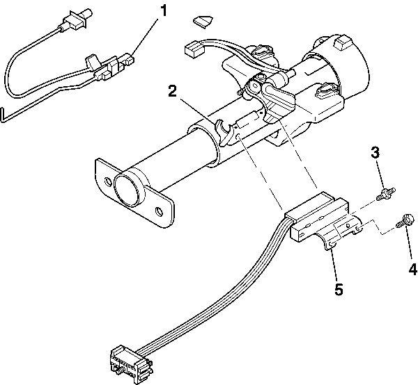
- Remove the following items from the ignition switch assembly (5):
- Remove the following items from the stud and bracket assembly (4):


Important: The BTSI cable assembly must remain straight during disassembly.
| 3.1. | Remove the hexagon washer head screw (2). |
| 3.2. | Remove the hexagon nut (1). |
| 3.3. | Remove the PRNDL adjuster assembly. |

| 4.1. | Remove the TORX® washer head screw (4). |
| 4.2. | Remove the dimmer switch mounting stud (3). |
| 4.3. | Remove the ignition switch assembly (5) from the stud and bracket assembly (2). |
| 4.4. | Remove the ignition switch assembly (5) from the ignition switch actuator assembly (1). |

| 5.1. | Remove the TORX® washer head screw (5). |
| 5.2. | Remove the cam retainer (2). |
| 5.3. | Remove the cable shift cam assembly (3). |
| 5.4. | Disconnect the park position switch assembly connector (1) from the interlock solenoid assembly. |
| 5.5. | Remove the park position switch assembly (1). |
