GM Service Manual Online
For 1990-2009 cars only

Steering Shaft, Lower Bearing, and Jacket - Assemble - Off Vehicle Floor Shift

Assembly Procedure

Tools Required

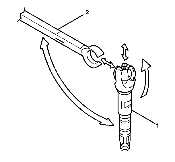
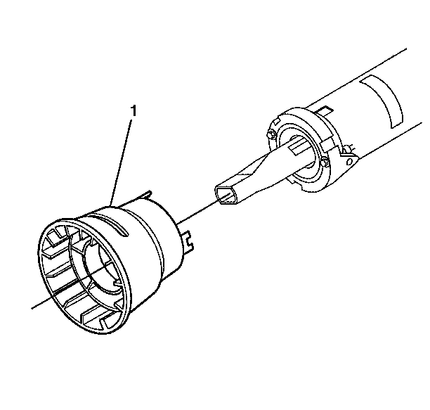
J 23072 Shift Tube Remover

   • 
Object Number: 390526  Size: SH
  • Install the steering column shroud (2) to the steering column jacket assembly (3).
  •    • 
  • Install the lock plate (1).
  •    • 
    Object Number: 390527  Size: SH
  • Install the steering column housing support assembly (2).
  •    • 

    Notice: Use the correct fastener in the correct location. Replacement fasteners must be the correct part number for that application. Fasteners requiring replacement or fasteners requiring the use of thread locking compound or sealant are identified in the service procedure. Do not use paints, lubricants, or corrosion inhibitors on fasteners or fastener joint surfaces unless specified. These coatings affect fastener torque and joint clamping force and may damage the fastener. Use the correct tightening sequence and specifications when installing fasteners in order to avoid damage to parts and systems.

  • Install the 4 support screws (1) to the steering column housing assembly (2).
  • Tighten
    Tighten the 4 support screws to 9 N·m (80 lb in).

       • 
  • Install the ignition switch assembly. Refer to Ignition Switch Assembly - Assemble - Off Vehicle .
  •    • 
    Object Number: 306318  Size: SH
  • Lubricate the exposed area of the race and upper shaft assembly (1).
  •    • 
  • Install the race and upper shaft assembly (1) to the lower steering shaft assembly (2).
  •    • 
  • Align the mark on the race and upper shaft assembly (1) to the mark on the lower steering shaft assembly (2).
  •    • 
  • Tilt the race and upper shaft assembly (1) 90 degrees to the lower steering shaft assembly (2) to engage.
  •    • 
    Object Number: 343889  Size: SH
  • Install the steering shaft assembly to the steering column.
  •    • 
    Object Number: 343881  Size: SH
  • Install the adapter and bearing assembly (1).
  •    • 
    Object Number: 343874  Size: SH
  • Install the following 3 items to the steering column jacket assembly:
  • 0.1. Install the lower bearing seat (3).
    0.2. Install the lower bearing spring (2).
    0.3. Install the lower spring retainer (1).
       • 
    Object Number: 388560  Size: SH
  • Install the following 3 items to the steering column jacket assembly:
  • 0.1. Install the steering wheel speed sensor assembly (2) to the adapter and bearing assembly (1).
    0.2. Install the sensor retainer (3).
    0.3. Install the steering shaft seal (4).
        • Install the steering column housing assembly. Refer to Steering Column Jacket - Assemble - Off Vehicle .

    Steering Shaft, Lower Bearing, and Jacket - Assemble - Off Vehicle Column Shift

    Assembly Procedure

    Tools Required

    J 23073-01 Shift Tube Installer

        • Install the ignition switch assembly. Refer to Ignition Switch Assembly - Assemble - Off Vehicle .
        • Install the interlock solenoid assembly. Refer to Automatic Transmission Shift Lock Control Assemble - Off Vehicle .
       • 
    Object Number: 387379  Size: SH
  • Install the gear shift lever bowl assembly (8).
  •    • 
  • Install the shift tube assembly (7) using J 23073-01 .
  •    • 
  • Install the shift lever spring (9).
  •    • 
  • Install the shift bowl protector (1).
  •    • 
  • Install the 2 thrust washers (6).
  •    • 
  • Lubricate the wave washer (5).
  •    • 
  • Install the wave washer (5).
  •    • 
  • Install the lock plate (4) following these steps:
  • 0.1. Turn the gear shift lever bowl assembly (8) clockwise to the 4 o' clock position.
    0.2. Push the lock plate (4) to the 1 o'clock position.
    0.3. Rotate the lock plate (4) counter clockwise until loose.
       • 
  • Install the 2 thrust washers (3).
  • Install the shift tube retaining ring (2).

       • 
    Object Number: 306318  Size: SH
  • Lubricate the exposed area of the race and upper shaft assembly (1).
  •    • 
  • Install the race and upper shaft assembly (1) to the lower steering shaft assembly (2) following these steps:
  • 0.1. Align the mark on the race and upper shaft assembly (1) to the mark on the lower steering shaft assembly (2).
    0.2. Tilt the race and upper shaft assembly (1) 90 degrees to the lower steering shaft assembly (2) to engage.
       • 
    Object Number: 387382  Size: SH
  • Install the shift lever gate (1).
  •    • 
  • Install the 2 oval head cross recess screws (5).
  • Notice: Use the correct fastener in the correct location. Replacement fasteners must be the correct part number for that application. Fasteners requiring replacement or fasteners requiring the use of thread locking compound or sealant are identified in the service procedure. Do not use paints, lubricants, or corrosion inhibitors on fasteners or fastener joint surfaces unless specified. These coatings affect fastener torque and joint clamping force and may damage the fastener. Use the correct tightening sequence and specifications when installing fasteners in order to avoid damage to parts and systems.

    Tighten
    Tighten the 2 oval head cross recess screws (5) to 4 N·m (35 lb in).

       • 
  • Install the steering column housing support assembly (3) to the gear shift lever bowl assembly (4).
  • Important: The shift tube assembly must fit into the hole of the steering column housing support assembly (3).

    The steering column jacket assembly must bottom out into the steering column housing support assembly (3).

       • 
  • Install the 4 support screws (2) to the steering column housing assembly (3).
  • Tighten
    Tighten the 4 support screws (2) to 9 N·m (80 lb in).

       • 
  • Install the shift lever.
  •    • 
    Object Number: 343889  Size: SH
  • Install the steering shaft assembly.
  •    • 
    Object Number: 343881  Size: SH
  • Lubricate the inner surface of the lower bearing with lithium grease.
  •    • 
  • Install the adapter and bearing assembly (1).
  •    • 
    Object Number: 343874  Size: SH
  • Install the lower bearing seat (3).
  •    • 
  • Install the lower bearing spring (2).
  •    • 
  • Install the lower spring retainer (1) onto the steering shaft assembly.
  •    • 

    Important: The lower bearing spring (2) must be flush with the adapter and bearing assembly.

  • Press the lower spring retainer (1) onto the steering shaft assembly.
  •    • 
    Object Number: 388560  Size: SH
  • Install the steering wheel speed sensor (2) to the adapter and bearing assembly (1).
  •    • 
  • Install the sensor retainer (3).
  •    • 
  • Install the steering shaft seal (4) to the sensor retainer (3).
  •    • 
  • Install the steering column housing assembly. Refer to Steering Column Jacket - Assemble - Off Vehicle .