Wheel Drive Shaft Outer Joint and Boot Replacement Tripot Joint 2.2L
Disassembly Procedure
Tools Required
| • | J 41398 CV Puller |
| • | J 2619-01 Slide Hammer Assembly |
- Remove the large boot retaining clamp from the CV joint with a side cutter. Discard the large boot retaining clamp.
- Remove the small boot retaining clamp from the halfshaft bar with a side cutter and discard.
- Separate the CV joint boot from the CV joint race (2) at the large diameter.
- Slide the boot away from the joint along the halfshaft bar.
- Wipe the grease from the face of the CV joint inner race (1).
- Before removing the CV joint assembly from the halfshaft bar, perform the following procedure:
- Clamp the halfshaft (1) into a vise.
- Attach the J 41398 to the threaded area of the outer race (2).
- Attach J 2619-01 onto the outer end of the J 41398 .
- Use the J 2619-01 to remove the CV joint from the halfshaft bar.
- Remove J 2619-01 and J 41398 from the CV joint.
- Remove the retaining ring from the halfshaft bar. Discard the retaining ring.
- Remove the CV joint boot (1) from the halfshaft bar.
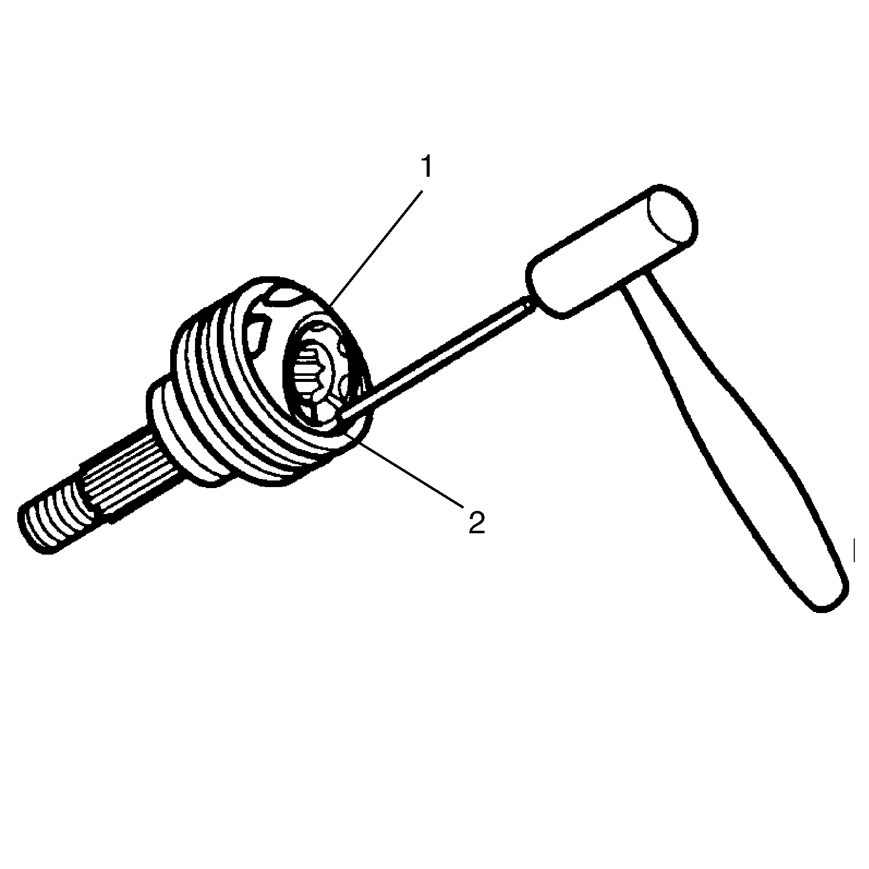
- Place a brass drift against the CV joint cage (1).
- Tap gently on the brass drift with a hammer in order to tilt the cage (1).
- Remove the first chrome alloy ball (2) when the CV joint cage (1) tilts.
- Tilt the CV joint cage (1) in the opposite direction to remove the opposing chrome alloy ball (2).
- Repeat this process to remove all six of the balls.
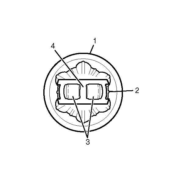
- Pivot the CV joint cage (4) and the inner race 90 degrees to the centerline of the outer race (1). At the same time, align the cage windows with the lands of the outer race (2).
- Lift out the cage (4) and the inner race.
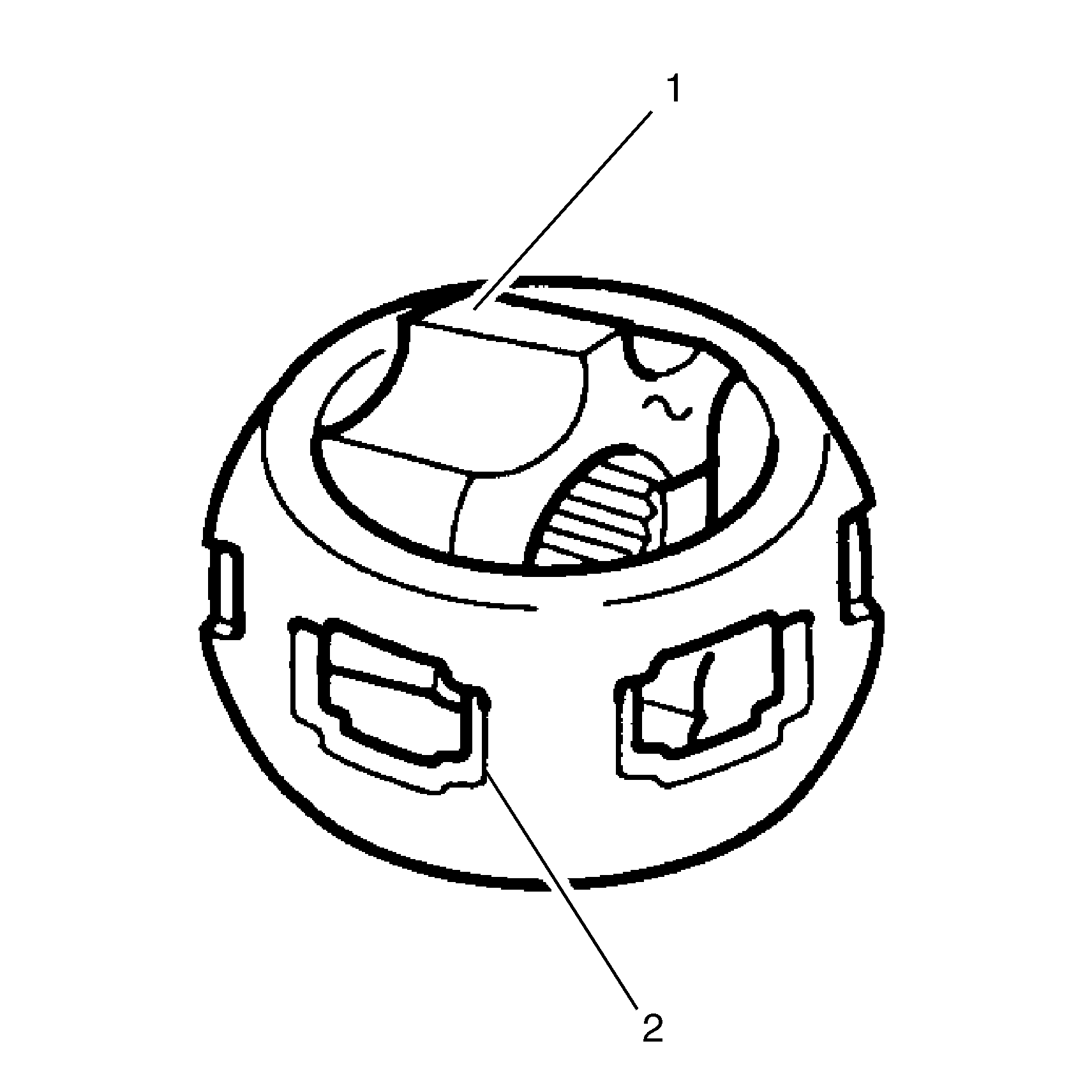
- Remove the inner race (1) from the cage (2) by rotating the inner race (1) upward.
- Clean the inner and outer race assemblies, the CV joint cage and the chrome alloy balls thoroughly with cleaning solvent. Remove all traces of old grease and any contaminates.
- Dry all the parts.
- Check the CV joint assembly for unusual wear, cracks, or other damage.
- Replace any damaged parts.
- Clean the halfshaft bar. Use a wire brush to remove any rust in the boot mounting area (grooves).

Important: Due to the helical splines on the halfshaft bar, disassembly and assembly of the joints will be difficult. Follow the instructions provided.
| 6.1. | Choose a reference mark (B) on the halfshaft bar. |
| 6.2. | Measure the distance between the reference mark (B) and the face of the CV joint inner race (1). Make a note of this measurement. The measurement is (A). |


Important: Never reuse the retaining ring.
Assembly Procedure
Tools Required
J 35910 Seal Clamp Tool
- Put a light coat of grease from service kit on the ball grooves of the inner race and the outer race.
- Hold the inner race 90 degrees to the centerline of the cage with the lands of the inner race (1) aligned with the windows of cage (2).
- Insert the inner race into the cage.
- Hold the cage and the inner race 90 degrees to the centerline of the outer race. Align the cage windows (3) with the lands of the outer race (2).
- Install the cage and the inner race into outer race.
- Place a brass drift against the CV joint cage (1).
- Tap gently on the brass drift with a hammer in order to tilt the cage (1).
- Install the first chrome alloy ball (2) when the CV joint cage (1) tilts.
- Repeat this process to install all six of the balls.
- Pack the CV joint with half of the grease supplied in the service kit.
- Install the new small retaining clamp (2) on the neck of the boot (3). Do not crimp.
- Clean the halfshaft bar (1). Use a wire brush to remove any rust in the boot mounting area (grooves).
- Slide the CV joint boot (3) onto the halfshaft bar (1). Expose the reference mark (4) by sliding the CV joint boot (3) up the halfshaft bar (1) toward the tripot end.
- Position the large boot retaining clamp around the joint boot.
- Place the new retaining ring onto the halfshaft bar.
- While supporting the tripot assembly, place the halfshaft assembly onto the arbor press with the CV assembly under the press head.
- Lower the arbor press head onto the CV joint assembly until the press cannot move any further. This ensures that the retaining ring engages in the inner race. Do not exceed 4,000 lbs press load during assembly.
- Remove the halfshaft assembly from the arbor press.
- Measure the distance between the reference mark on the halfshaft bar (B) and the face of the CV joint inner race (1).
- Compare the mark with the measurement made before disassembly. The distance measured after assembly must be within +-1 mm (.039") of the distance measured before disassembly.
- Repeat the previous four steps if the current measurement does not match the measurement made before disassembly.
- Place the neck of the CV joint boot into the boot groove on the halfshaft bar.
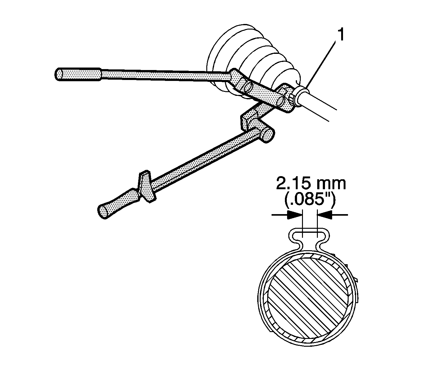
- Crimp the small retaining clamp (1) by using J 35910 , a breaker bar, and a torque wrench.
- Check the gap dimension. Continue tightening until the gap dimension is reached.
- Place the remaining grease from the service kit inside the boot.
- Measure approximately 17.5 mm (11/16 in) up from the bottom edge of the CV outer joint assembly.
- Slide the large diameter of the boot with the large boot retaining clamp in place over the outside of CV joint.
- Locate the boot lip to the ridge of the CV outer joint assembly as measured in the previous step.
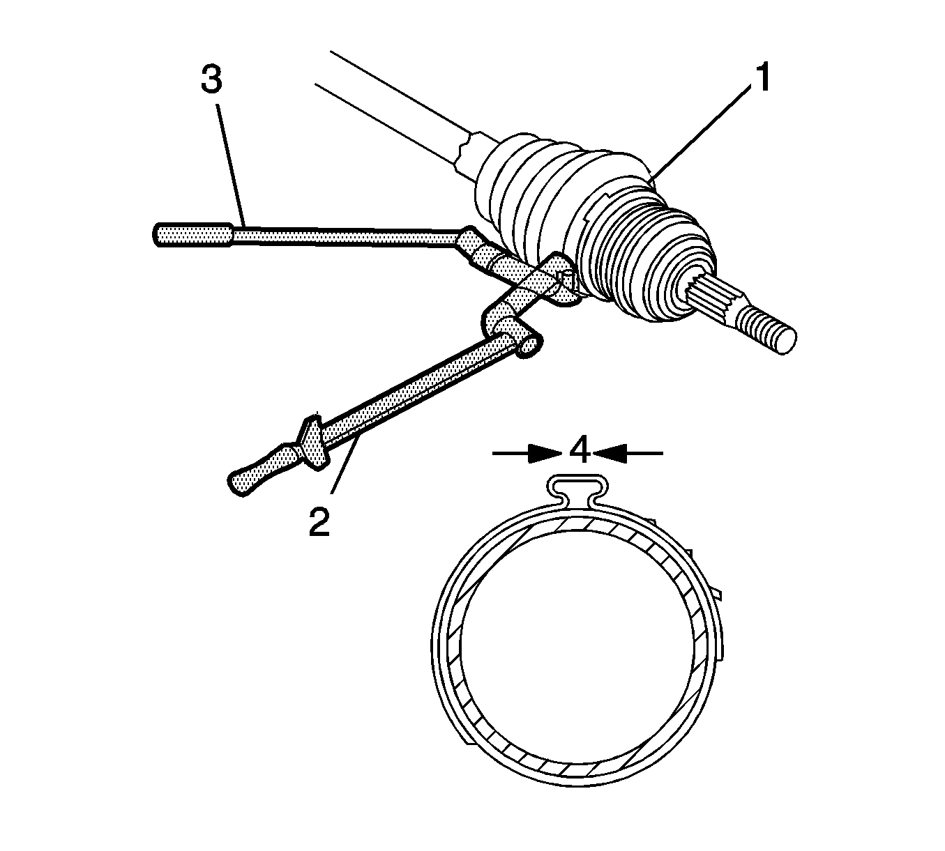
- Crimp boot retaining clamp (1) with J 35910 , a breaker bar (3), and a torque wrench (2).
- Check the gap dimension. Continue tightening until the correct gap dimension is reached.


Important: Ensure that the retaining ring side of the inner race faces the outer race.


Notice: Use the correct fastener in the correct location. Replacement fasteners must be the correct part number for that application. Fasteners requiring replacement or fasteners requiring the use of thread locking compound or sealant are identified in the service procedure. Do not use paints, lubricants, or corrosion inhibitors on fasteners or fastener joint surfaces unless specified. These coatings affect fastener torque and joint clamping force and may damage the fastener. Use the correct tightening sequence and specifications when installing fasteners in order to avoid damage to parts and systems.
Important: Check the clamp position during the crimping operation in order to ensure the clamp (1) is positioned correctly around the entire circumference.
Tighten
Tighten the boot retaining clamp to 136 N·m (100 lb ft).

Important: The CV joint boot must not be dimpled, stretched or out of shape in any way. If boot is not shaped correctly, equalize pressure in the boot and shape the boot properly by hand.
Tighten
Tighten boot retaining clamp to 176 N·m (130 lb ft).
Wheel Drive Shaft Outer Joint and Boot Replacement Free Motion Joint 2.4L
Disassembly Procedure
Tools Required
| • | J 41398 CV Puller |
| • | J 2619-01 Slide Hammer Assembly |
- Remove the large boot retaining clamp from the CV joint with a side cutter. Discard the large boot retaining clamp.
- Remove the small boot retaining clamp from the halfshaft bar with a side cutter and discard.
- Separate the CV joint boot from the CV joint race (2) at the large diameter.
- Slide the boot away from the joint along the halfshaft bar.
- Wipe the grease from the face of the CV joint inner race (1).
- Before removing the CV joint assembly from the halfshaft bar, perform the following procedure:
- Clamp the halfshaft (1) into a vise.
- Attach the J 41398 to the threaded area of the outer race (2).
- Attach J 2619-01 onto the outer end of the J 41398 .
- Use the J 2619-01 to remove the CV joint from the halfshaft bar.
- Remove J 2619-01 and J 41398 from the CV joint.
- Remove the retaining ring from the halfshaft bar. Discard the retaining ring.
- Remove the CV joint boot (1) from the halfshaft bar.
- Place a brass drift against the CV joint cage (1).
- Tap gently on the brass drift with a hammer in order to tilt the cage (1).
- Remove the first chrome alloy ball (2) when the CV joint cage (1) tilts.
- Tilt the CV joint cage (1) in the opposite direction to remove the opposing chrome alloy ball (2).
- Repeat this process to remove all six of the balls.
- Pivot the CV joint cage (4) and the inner race 90 degrees to the centerline of the outer race (1). At the same time, align the cage windows with the lands of the outer race (2).
- Lift out the cage (4) and the inner race.
- Remove the inner race (1) from the cage (2) by rotating the inner race (1) upward.
- Clean the inner and outer race assemblies, the CV joint cage and the chrome alloy balls thoroughly with cleaning solvent. Remove all traces of old grease and any contaminates.
- Dry all the parts.
- Check the CV joint assembly for unusual wear, cracks, or other damage.
- Replace any damaged parts.
- Clean the halfshaft bar. Use a wire brush to remove any rust in the boot mounting area (grooves).

Important: Due to the helical splines on the halfshaft bar, disassembly and assembly of the joints will be difficult. Follow the instructions provided.
| 6.1. | Choose a reference mark (B) on the halfshaft bar. |
| 6.2. | Measure the distance between the reference mark (B) and the face of the CV joint inner race (1). Make a note of this measurement. The measurement is (A). |


Important: Never reuse the retaining ring.


Assembly Procedure
Tools Required
J 35910 Seal Clamp Tool
- Put a light coat of grease from service kit on the ball grooves of the inner race and the outer race.
- Hold the inner race 90 degrees to the centerline of the cage with the lands of the inner race (1) aligned with the windows of cage (2).
- Insert the inner race into the cage.
- Hold the cage and the inner race 90 degrees to the centerline of the outer race. Align the cage windows (3) with the lands of the outer race (2).
- Install the cage and the inner race into outer race.
- Place a brass drift against the CV joint cage (1).
- Tap gently on the brass drift with a hammer in order to tilt the cage (1).
- Install the first chrome alloy ball (2) when the CV joint cage (1) tilts.
- Repeat this process to install all six of the balls.
- Pack the CV joint with half of the grease supplied in the service kit.
- Install the new small retaining clamp on the neck of the boot. Do not crimp.
- Clean the halfshaft bar. Use a wire brush to remove any rust in the boot mounting area (grooves).
- Slide the CV joint boot onto the halfshaft bar. Expose the reference mark (B) by sliding the CV joint boot up the halfshaft bar toward the tripot end.
- Position the large boot retaining clamp around the joint boot.
- Place the new retaining ring in the inner race.
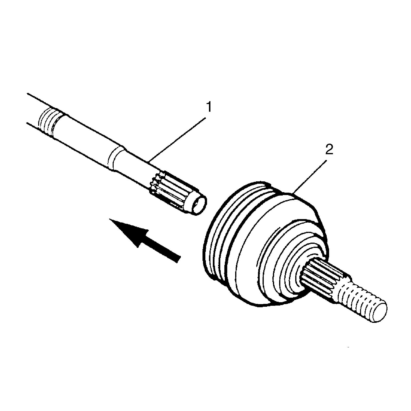
- Slide the CV joint (2) on the halfshaft bar (1).
- Measure the distance between the reference mark on the halfshaft bar (B) and the face of the CV joint inner race (1).
- Compare the mark with the measurement made before disassembly. The distance measured after assembly must be within +-1 mm of the distance measured before disassembly.
- Repeat the previous four steps if the current measurement does not match the measurement made before disassembly.
- Place the neck of the CV joint boot into the boot groove on the halfshaft bar.
- Crimp the small retaining clamp (1) by using J 35910 , a breaker bar, and a torque wrench.
- Check the gap dimension. Continue tightening until the gap dimension is reached.
- Place the remaining grease from the service kit inside the boot.
- Measure approximately 17.5 mm (11/16 in) up from the bottom edge of the CV outer joint assembly.
- Slide the large diameter of the boot with the large boot retaining clamp in place over the outside of CV joint.
- Locate the boot lip to the ridge of the CV outer joint assembly as measured in the previous step.
- Crimp the boot retaining clamp (1) with J 35910 , a breaker bar (3) and a torque wrench (2).
- Check the gap dimension. Continue tightening until the correct gap dimension is reached.


Important: Ensure that the retaining ring side of the inner race faces the halfshaft bar.




Notice: Use the correct fastener in the correct location. Replacement fasteners must be the correct part number for that application. Fasteners requiring replacement or fasteners requiring the use of thread locking compound or sealant are identified in the service procedure. Do not use paints, lubricants, or corrosion inhibitors on fasteners or fastener joint surfaces unless specified. These coatings affect fastener torque and joint clamping force and may damage the fastener. Use the correct tightening sequence and specifications when installing fasteners in order to avoid damage to parts and systems.
Important: Check the clamp position during the crimping operation in order to ensure the clamp (1) is positioned correctly around the entire circumference.
Tighten
Tighten the boot retaining clamp to 136 N·m (100 lb ft).

Important: The CV joint boot must not be dimpled, stretched or out of shape in any way. If boot is not shaped correctly, equalize pressure in the boot and shape the boot properly by hand.

Tighten
Tighten the boot retaining clamp to 176 N·m (130 lb ft).
