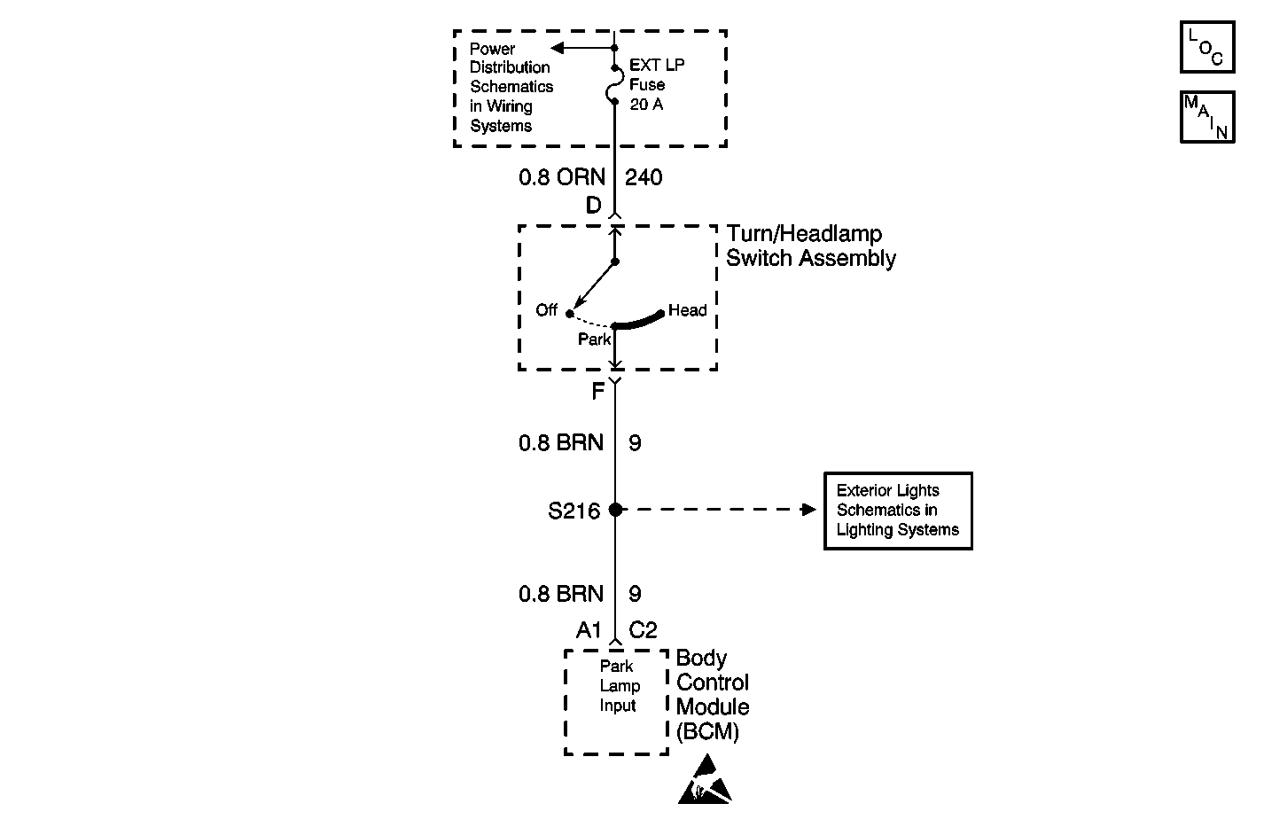
Circuit Description
The parklamps are controlled by the turn/headlamp switch. Positive battery voltage is supplied to the switch through the EXT LP fuse. When the turn/headlamp switch is placed in the park or head position, battery voltage is supplied to the park lamps through CKT 9. The body control module is also connected to CKT 9 to sense whether or not the parklamps turn on when the lowbeam or highbeam headlamps are turned on. If the BCM senses that the lowbeam or highbeam headlamps are on and the parklamp input is not active, DTC B2662 sets.
Conditions for Running the DTC
| • | The ignition switch is on. |
| • | The lowbeam or highbeam headlamps are on. |
Conditions for Setting the DTC
The parklamp input is inactive for 1 second.
Action Taken When the DTC Sets
DTC B2662 is stored in the BCM memory.
Conditions for Clearing the DTC
| • | A current DTC B2662 will clear when the malfunction is no longer present and the ignition switch is cycled. |
| • | All BCM history codes clear after 100 ignition cycles (from OFF to ON) with no current codes active during the 100 ignition cycles. |
Diagnostic Aids
| • | The low or highbeam headlamps must be on in order for this DTC to set. |
| • | An open EXT LP fuse will set this code. |
| • | If the DTC is a history DTC, the problem may be intermittent. Try performing tests while wiggling the wiring and connectors. This can often cause the malfunction to appear. |
Test Description
The number(s) below refer to the step number(s) on the diagnostic table.
-
The scan tool PARKLAMP INPUT parameter will display ON with the parklamps on, if the system is operating properly.
-
The scan tool PARKLAMP INPUT parameter will change to OFF with the parklamps off, if the system is operating properly.
-
The scan tool PARKLAMP INPUT parameter should display OFF with the parklamp switch disconnected, if the system is operating properly.
Step | Action | Yes | No |
|---|---|---|---|
1 | Did you perform the Lighting Systems Diagnostic System Check? | Go to Step 2 | Go to A Diagnostic System Check - Lighting Systems |
Does the scan tool display ON? | Go to Step 3 | Go to Step 5 | |
Does the PARKLAMP INPUT parameter change state? | Go to Diagnostic Aids | Go to Step 4 | |
Does the scan tool display OFF? | Go to Step 7 | Go to Step 5 | |
5 | Test the signal circuit of the turn/headlamp switch for an open or short to ground. Refer to Circuit Testing and Wiring Repairs in Wiring Systems. Did you find and correct the condition? | Go to Step 10 | Go to Step 6 |
6 | Inspect for poor connections at the harness connector of the BCM. Refer to Testing for Intermittent and Poor Connections and Connector Repairs in Wiring Systems. Did you find and correct the condition? | Go to Step 10 | Go to Step 8 |
7 | Inspect for poor connections at the harness connector of the turn/headlamp switch. Refer to Testing for Intermittent and Poor Connections and Connector Repairs in Wiring Systems. Did you find and correct the condition? | Go to Step 10 | Go to Step 9 |
8 |
Important: Perform the set up procedure for the BCM. Refer BCM Programming/RPO Configuration in Body Control System. Replace the BCM. Refer to BCM Replacement in Body Control System. Did you complete the replacement? | Go to Step 10 | -- |
9 | Replace the turn/headlamp switch. Refer to Multifunction, Turn Signal and Hazard Switch Replacement in Steering Wheel and Column. Did you complete the replacement? | Go to Step 10 | -- |
10 |
Does the DTC reset? | Go to Step 2 | System OK |
