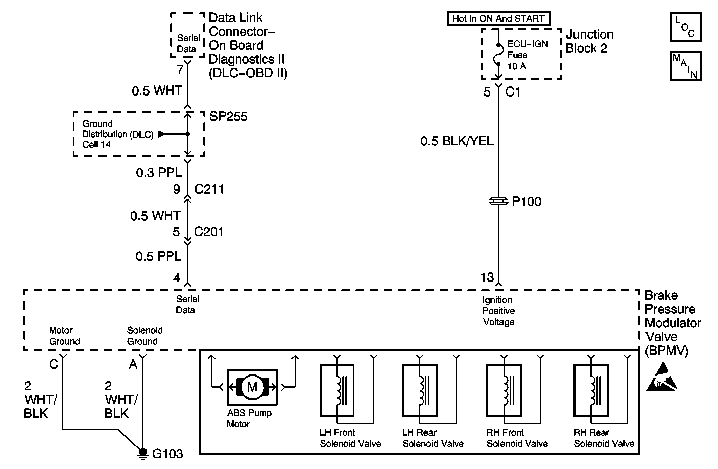
System Description
The Diagnostic System Check is an organized approach to identifying an Antilock Brake System (ABS) malfunction. The Diagnostic System Check must be the starting point for any ABS complaint diagnosis. The Diagnostic System Check directs the service technician to the next logical step in diagnosing the complaint.
Circuit Description
The Electronic Brake Control Module (EBCM) receives ignition current through terminal 13. The EBCM receives battery current through terminal D (for pump motor) and terminal B (for solenoid valves). The EBCM is grounded through terminal C and terminal A.
The EBCM interfaces with a scan tool through terminal 4 via to OBD2 Data Link Connector (DLC) terminal 7. A properly set scan tool connected to the DLC can retrieve ABS diagnostic information like Diagnostic Trouble Codes (DTCs) and perform ABS device control for testing purposes.
Diagnostic Aids
Inspect for the following list of items when diagnosing this part of the Antilock Brake System (ABS):
| • | An open ECU-IG fuse |
| • | An open ABS fuse |
| • | A clean tight G103 |
The Electronic Brake Control Module (EBCM) will not interface with a scan tool if these circuits have excessive resistance:
| • | The serial data line |
| • | The ignition power circuit |
| • | G103 and G200 |
Ensure these circuits are in good condition and that no excessive resistance occurs. Also check the EBCM electrical connector for poor connector terminal contact.
Test Description
The number(s) below refer to the step number(s) on the diagnostic table.
-
Tests the ABS warning indicator status. When a Diagnostic Trouble Code (DTC) is stored the ABS lamp stays ON steady. When the ABS lamp turns ON for 3 seconds then turns OFF the ABS is OK. If the ABS warning indicator does not turn ON at all the ABS has an electrical problem (power and or grounds to the EBCM and or the ABS warning indicator).
-
Test the ABS for possible DTCs set after an ABS stop.
-
Tests for proper interface between a scan tool and the EBCM.
-
Tests for any stored History DTCs.
-
Tests for possible Current DTC.
-
Determines whether the EBCM has DTCs stored or the ABS has a power and or ground and or ABS warning indicator circuit problem.
-
Tests the scan tool for proper operation. A malfunctioning will lead to wrong diagnosis.
-
Tests for an open in the serial data line (PPL wire).
-
Up to five DTCs can be stored in the EBCM at any given time. In case that there is another DTC and five have already been set the EBCM will replace the least significant DTC with the new DTC.
-
Only one Current DTC is displayed for the duration of the ignition cycle.
-
Capture Data contains SNAP SHOT data (wheel speed sensor speeds, ABS status, stoplamp status) from the most recently set DTC.
-
Directs the technician to the corresponding DTC table in this section for the proper diagnosis of the ABS.
Step | Action | Value(s) | Yes | No | ||||||
|---|---|---|---|---|---|---|---|---|---|---|
Did the ABS indicator turn ON for 3 seconds and then turn OFF? | -- | Go to Step 2 | Go to Step 6 | |||||||
Is the ABS indicator ON? | -- | Go to Step 3 | System OK | |||||||
Did scan tool establish communication with the vehicle? | -- | Go to Step 4 | Go to Step 7 | |||||||
Were there any History DTCs stored? | -- | Go to Step 9 | Go to Step 5 | |||||||
Select the Current Diagnostic Trouble Codes on the scan tool. Were there any Current DTCs stored? | -- | Go to Step 11 | Go to Step 17 | |||||||
Is the ABS indicator ON steady? | -- | Go to Step 3 | Go to Step 13 | |||||||
Test the scan tool for proper operation. Refer to the users manual for additional information. Is the scan tool in good operating condition? | -- | Go to Step 8 | Go to Step 14 | |||||||
Is the resistance within the specified range? | 0-2 ohms | Go to Step 16 | Go to Step 15 | |||||||
Gather and record all History DTCs before proceeding with next step. Is the action complete? | -- | Go to Step 10 | -- | |||||||
Is the action complete? | -- | Go to Step 11 | -- | |||||||
Is the action complete? | -- | Go to Step 12 | -- | |||||||
Go to the corresponding DTC table(s) for further diagnosis and repair of the ABS as follows:
Is the action complete? | -- | Go to Step 1 | -- | |||||||
13 | Refer to the ABS Indicator Inoperative table for further diagnosis. Is the action complete? | -- | Go to Step 1 | -- | ||||||
14 | Install a known-good scan tool to the OBD2 Data Link Connector (DLC). Is the action complete? | -- | Go to Step 3 | -- | ||||||
15 | Repair an open or a high resistance in the Serial Data Line between the EBCM and the OBD2 Data Link Connector (DLC). Is the repair complete? | -- | Go to Step 1 | -- | ||||||
16 |
Is the action complete? | -- | Go to Step 1 | -- | ||||||
17 | Refer to ABS Indicator Always On for further diagnosis. Is the action complete? | -- | Go to Step 1 | -- |
