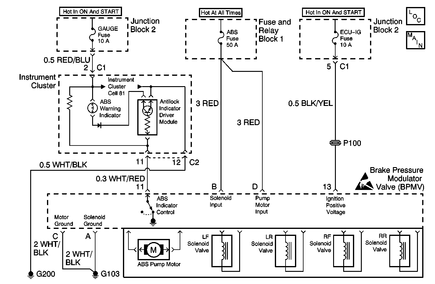
Circuit Description
The Electronic Brake Control Module (EBCM) turns OFF the ABS warning indicator by grounding terminal 11 after Initilization.
The ABS warning indicator is connected to the gauge fuse. This circuit has power when the ignition switch is in the ON or START positions.
When the ignition switch is turned to the ON position, the EBCM turns ON the ABS warning indicator for 3 seconds for a bulb check. If the EBCM detects a malfunction, the ABS warning indicator will stay ON to warn the driver that the ABS is disabled and it needs service.
Diagnostic Aids
Inspect for the following when diagnosing this part of the Antilock Brake System (ABS):
| • | Open gauge fuse |
| • | Open ABS warning indicator bulb filament |
| • | Open or poor G103 |
| • | Open within Instrument panel gage cluster printed circuit |
Inspect the following harness connectors:
| • | For backed-out terminals |
| • | For improper mating |
| • | For broken locks |
| • | For improperly formed or damaged terminals |
| • | For poor terminal to wiring connections |
| • | For physical damage to the wiring harness before component replacement: |
| - | Instrument panel gage cluster electrical connectors |
| - | Junction block electrical connectors |
| - | EBCM electrical connector |
Test Description
The number(s) below refer to the step number(s) on the diagnostic table.
-
Tests for power distribution to the instrument panel gage cluster.
-
Tests for power distribution to the EBCM (ignition power).
-
Tests for power distribution to the EBCM for motor and solenoids.
-
Tests for proper ground to the EBCM.
Step | Action | Value(s) | Yes | No |
|---|---|---|---|---|
1 | Did you perform A Diagnostic System Check - ABS? | -- | Go to Step 2 | |
Test the ABS Indicator I/P input circuit for an open or short to ground. Refer to Circuit Testing and Wiring Repairs in Wiring System Was a problem found and corrected? | -- | Go to Step 3 | ||
Test the Ignition Positive Voltage circuit for an open or short to ground. Refer to Circuit Testing and Wiring Repairs in Wiring System Was a problem found and corrected? | -- | Go to Step 4 | ||
Test the Solenoid Input and the Pump Motor Input circuits for an open or short to ground. Refer to Circuit Testing and Wiring Repairs in Wiring System Was a problem found and corrected? | -- | Go to Step 5 | ||
Test the Solenoid Ground and the Pump Motor Ground circuits for an open or high resistance. Refer to Circuit Testing and Wiring Repairs in Wiring System Was a problem found and corrected? | -- | Go to Step 6 | ||
6 | Test the ABS Indicator Control circuit for an open or short to ground. Refer to Circuit Testing and Wiring Repairs in Wiring System Was a problem found and corrected? | -- | Go to Step 7 | |
7 |
Is the ABS indicator bulb filament open? | -- | Go to Step 8 | Go to Step 9 |
8 | Replace the ABS indicator bulb. Refer to Instrument Cluster Bulb Replacement in Instrument Panel, Gages, and Console. Is the repair complete? | -- | -- | |
9 |
Does the DTC reset? | -- | Go to Step 10 | |
10 | Replace the Brake Modulator Assembly. Refer to Brake Pressure Modulator Valve Assembly Replacement . Is the repair complete? | -- | -- |
