Step | Action | Yes | No | ||||||||||||||||||||||||||
|---|---|---|---|---|---|---|---|---|---|---|---|---|---|---|---|---|---|---|---|---|---|---|---|---|---|---|---|---|---|
The fans run at low speed (series configuration) when the A/C is operating and the engine coolant temperature (ECT) is below 83°C (181°F). The fans run at high speed (parallel configuration) when the ECT is above 93°C (199°F). An open in the ground circuit for the fan no. 1 and no. 2 relay coils will cause the fans to run continuously with the ignition switch in the RUN position and the ECT below 93°C (199°F). | |||||||||||||||||||||||||||||
The following are symptoms and possible causes.
| |||||||||||||||||||||||||||||
1 | Did you perform the HVAC System Check? | Go to Step 2 | Go to the HVAC System Check | ||||||||||||||||||||||||||
2 |
Is only the main fan motor running continuously? | Go to Step 5 | Go to Step 3 | ||||||||||||||||||||||||||
3 | Is only the auxiliary fan motor running continuously? | Go to Step 9 | Go to Step 4 | ||||||||||||||||||||||||||
4 | Are both fan motors running continuously? | Go to Step 12 | Go to Step 1 | ||||||||||||||||||||||||||
5 | Remove the fan no. 1 relay from fuse and relay block 1. Does the main fan motor run? | Go to Step 6 | Go to Step 7 | ||||||||||||||||||||||||||
6 | Repair the short to voltage in the BLK/RED wire between the main fan motor terminal 2 and fuse and relay block 1. Refer to Wiring Repairs in Wiring Systems. Is the repair complete? | Go to the HVAC System Check | -- | ||||||||||||||||||||||||||
7 | Test for an open in the BLU/BLK wire between the fan no. 1 relay in fuse and relay block 1 and the A/C fan no. 2 relay in fuse and relay block 2. Is an open present? | Go to Step 16 | Go to Step 8 | ||||||||||||||||||||||||||
8 | Replace the fan no. 1 relay. Refer to Cooling Fan Relay Replacement in Engine Cooling. Is the repair complete? | Go to the HVAC System Check | -- | ||||||||||||||||||||||||||
9 | Remove the A/C fan no. 2 relay from fuse and relay block 2. Does the auxiliary fan motor run? | Go to Step 10 | Go to Step 11 | ||||||||||||||||||||||||||
10 | Repair the short to ground in the WHT wire between the auxiliary fan motor terminal 1 and fuse and relay block 2. Refer to Wiring Repairs in Wiring Systems. Is the repair complete? | Go to the HVAC System Check | -- | ||||||||||||||||||||||||||
11 | Replace the A/C fan no. 2 relay. Refer to Condenser Fan Relay Replacement . Is the repair complete? | Go to the HVAC System Check | -- | ||||||||||||||||||||||||||
12 | Remove the A/C fan no. 3 relay from fuse and relay block 2. Do both fan motors run? | Go to Step 13 | Go to Step 18 | ||||||||||||||||||||||||||
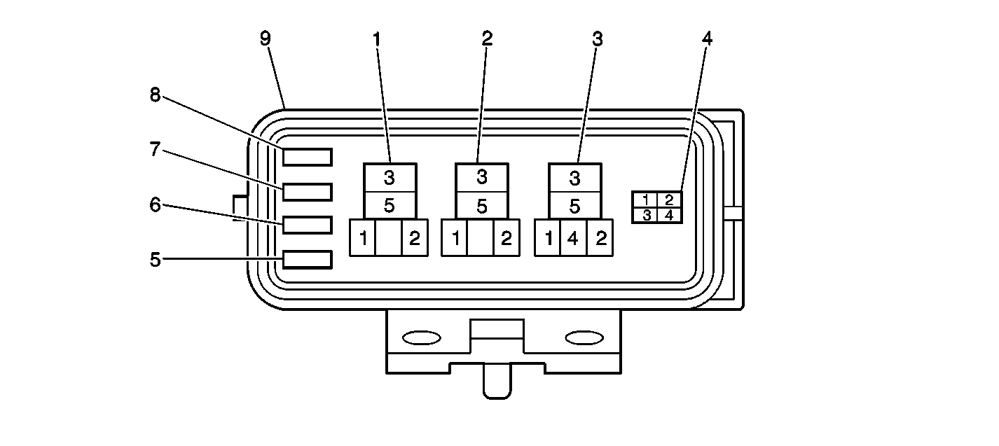
13 |
Is an open present? | Go to Step 16 | Go to Step 14 | ||||||||||||||||||||||||||
14 | Test for an open in the A/C refrigerant pressure switch. Is an open present? | Go to Step 15 | Go to Step 17 | ||||||||||||||||||||||||||
15 | Replace the A/C refrigerant pressure switch, if equipped. Refer to Air Conditioning (A/C) Refrigerant Pressure Sensor Replacement . Is the repair complete? | Go to the HVAC System Check | -- | ||||||||||||||||||||||||||
16 | Repair the open/short. Refer to Wiring Repairs in Wiring Systems. Is the repair complete? | Go to the HVAC System Check | -- | ||||||||||||||||||||||||||
17 | Inspect the ECT sensor for incorrect performance or for an incorrect input to the PCM. Refer to DTC P0116 Engine Coolant Temperature (ECT) Sensor Performance in Engine Controls. If the ECT sensor is operating correctly, replace the PCM. Refer to Powertrain Control Module Replacement in Engine Controls. Is the repair complete? | Go to the HVAC System Check | -- | ||||||||||||||||||||||||||
18 |
Does continuity exist in either relay? | Go to Step 19 | Go to Step 20 | ||||||||||||||||||||||||||
19 | Replace the faulty relay. Refer to Condenser Fan Relay Replacement . Is the repair complete? | Go to the HVAC System Check | -- | ||||||||||||||||||||||||||
20 | Repair the short to voltage in the BLK/WHT wire between the A/C fan no. 3 relay terminal 1 in fuse and relay block 2 and the A/C MG relay terminal 3 in fuse and relay block 2. Refer to Wiring Repairs in Wiring Systems. Is the repair complete? | Go to the HVAC System Check | -- | ||||||||||||||||||||||||||

