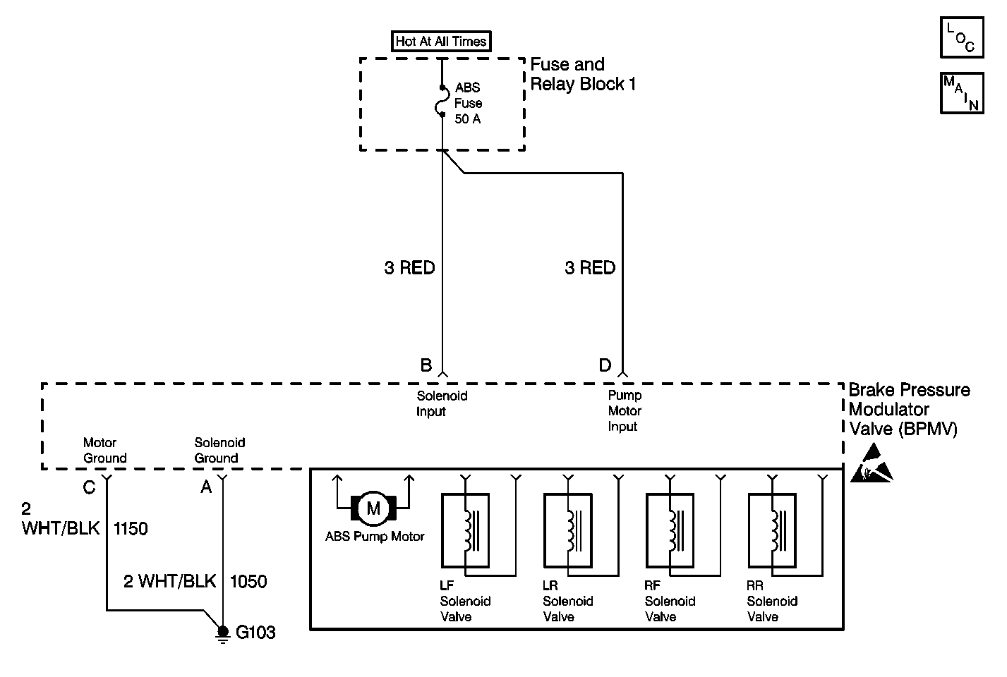
Circuit Description
The pump motor relay is part of the Electronic Brake Control Module (EBCM). The EBCM turns ON and OFF the pump motor relay as deemed necessary in order to activate the pump motor. The pump motor modulates brake hydraulic pressure during an ABS stop.
Conditions for Running the DTC
DTC C0116 can be set anytime the ignition switch is in the ON position.
Conditions for Setting the DTC
The Electronic Brake Control Module (EBCM) detects an open in the pump motor circuitry.
Action Taken When the DTC Sets
| • | The ABS disables |
| • | The ABS warning indicator turns ON |
Conditions for Clearing the DTC
The condition responsible for setting the DTC no longer exists and the Scan Tool Clear DTCs function is used. Although, after the scan tool erases DTC C0116, the EBCM keeps the ABS indicator ON until the vehicle is driven 10 mph for at least 20 seconds AND the pump motor sends a proper monitor signal to the EBCM. Then the EBCM turns OFF the ABS indicator. If the pump motor monitor signal is still incorrect, DTC C0116 will set again as a current DTC and the ABS indicator remains ON.
Diagnostic Aids
Inspect the ABS fuse when diagnosing this part of the Antilock Brake System (ABS)
Inspect the harness connectors for the following conditions:
| • | Backed-out terminals |
| • | Improper mating |
| • | Broken locks |
| • | Improperly formed or damaged terminals |
| • | Poor terminal to wiring connections or physical damage to the wiring harness |
Test Description
The numbers below refer to step numbers on the Diagnostic Table.
Step | Action | Value(s) | Yes | No |
|---|---|---|---|---|
1 | Did you perform A Diagnostic System Check - ABS? | -- | Go to Step 2 | |
Does the DTC reset? | -- | Go to Step 3 | Go to Testing for Intermittent Conditions and Poor Connections in Wiring Systems | |
3 |
Was a problem found and corrected? | -- | Go to Step 4 | |
4 | Replace the Brake Modulator Assembly. Refer to Brake Pressure Modulator Valve Assembly Replacement . Is the repair complete? | -- | Go to Step 5 | -- |
5 |
Does the DTC reset? | -- | Go to Step 2 | System OK |
