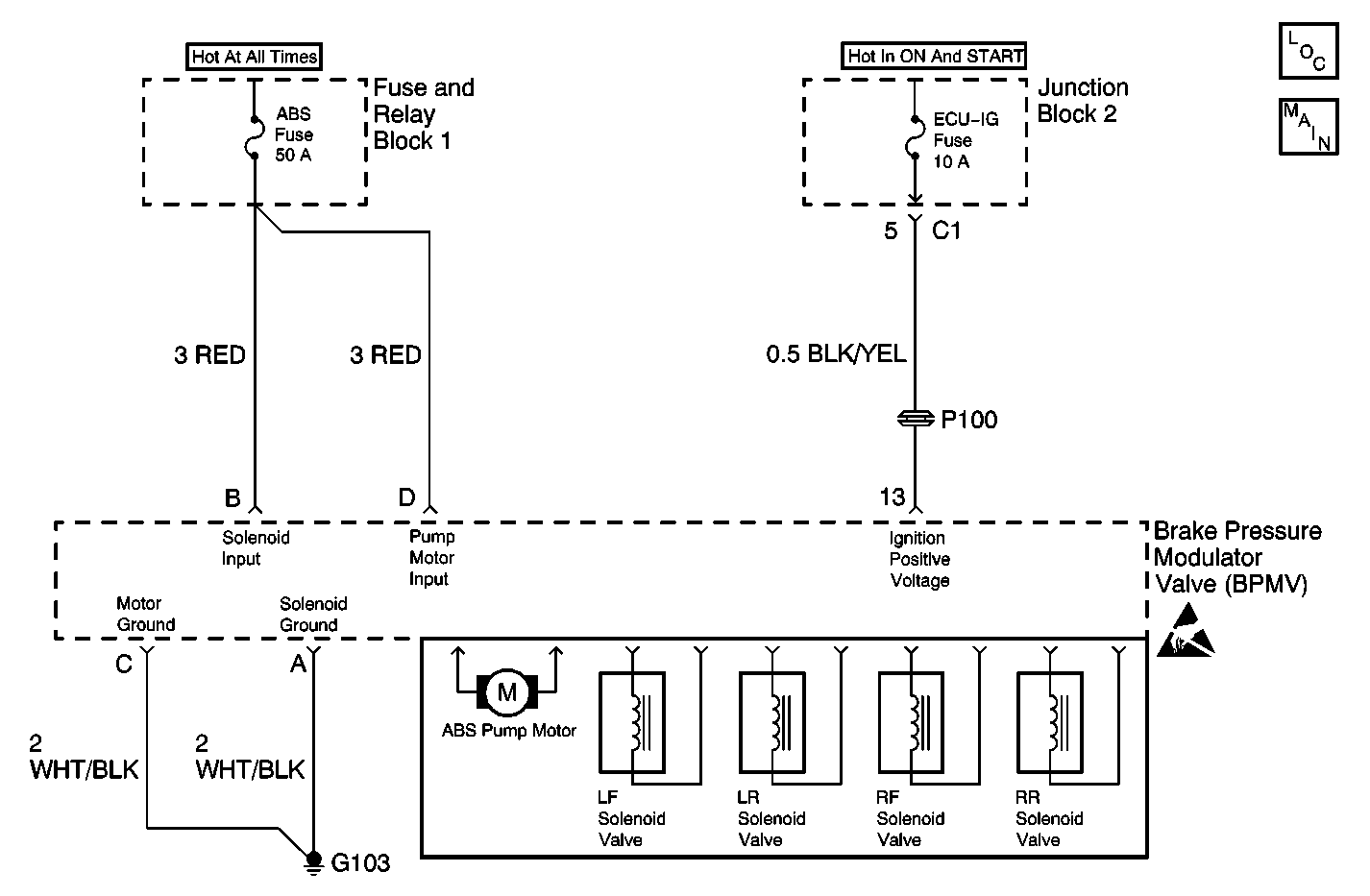
Circuit Description
This DTC is designed to detect high vehicle voltage levels and to protect the Antilock Brake System (ABS) system from high voltage damage.
Conditions for Running the DTC
DTC C0900 can be set anytime the ignition switch is in the ON position.
Conditions for Setting the DTC
Power voltage level circuit is greater than 17.5 volts.
Action Taken When the DTC Sets
| • | The ABS disables |
| • | The ABS warning indicator turns ON |
Conditions for Clearing the DTC
The condition responsible for setting the DTC no longer exists and the Scan Tool Clear DTCs function is used.
Diagnostic Aids
Use the enhanced diagnostic function of the Scan Tool in order to measure the frequency of the malfunction.
Ensure the vehicle's charging system is working properly.
Test Description
The numbers below refer to the step numbers on the diagnostic table.
-
This step uses the scan tool to check the battery positive voltage circuit to the EBCM.
-
This step checks the battery positive voltage supply circuit.
Step | Action | Value(s) | Yes | No |
|---|---|---|---|---|
1 | Did you perform A Diagnostic System Check - ABS? | -- | Go to Step 2 | |
Does the scan tool indicate that the battery voltage is less than the specified voltage? | 17 V | Go to Step 5 | Go to Step 3 | |
Does the voltage measure less than the specified value? | 17 V | Go to Step 4 | Go to Charging System Check in Engine Electrical | |
4 |
Does the DTC reset? | -- | Go to Step 5 | System OK |
5 | Replace the Brake Modulator Assembly. Refer to Brake Pressure Modulator Valve Assembly Replacement . Did you complete the repair? | -- | Go to Step 6 | -- |
6 |
Does the DTC reset? | -- | Go to Step 2 | System OK |
