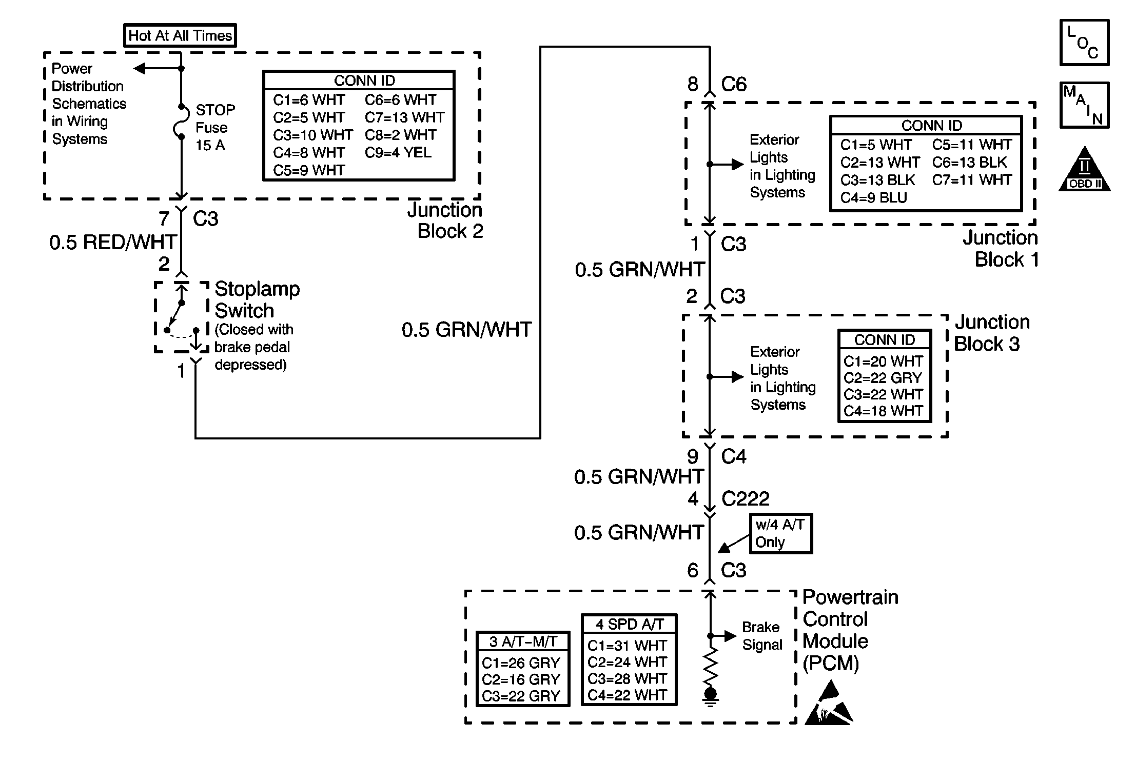
Circuit Description
The powertrain control module (PCM) will detect a malfunction when the stoplamp switch is in the closed position, and the stoplamps are ON, when the stoplamp switch should be open. The DTC P1520 is only supported on vehicles with an automatic transmission. If the stoplamp switch is closed, the PCM will not allow the TCC lock-up to occur. The PCM also uses the stoplamp switch input for fuel cut-off control.
Conditions for Running the DTC
| • | The engine is running. |
| • | The vehicle speed is more than 30 km/h (19 mph). |
Conditions for Setting the DTC
The stoplamp switch always remains in the ON position.
Action Taken When the DTC Sets
| • | The PCM illuminates the malfunction indicator lamp (MIL) after 2 consecutive ignition cycles in which the diagnostic runs with the fault active. |
| • | The PCM stores the conditions which were present when the DTC set as Freeze Frame data. |
Conditions for Clearing the MIL/DTC
| • | The PCM turns OFF the MIL on the third consecutive trip cycle during which the diagnostic has been run and the fault condition is no longer present. |
| • | The DTC clears after 40 consecutive warm-up cycles have occurred without a fault. |
| • | A DTC can be cleared by using the scan tool Clear DTC Information function. |
Diagnostic Aids
An intermittent malfunction may be caused by a fault in the stoplamp switch electrical circuit. Inspect the wiring harness and the components for any of the following conditions:
| • | Any backed-out terminals |
| • | Any improper mating of terminals |
| • | Any broken electrical connector locks |
| • | Any improperly formed or damaged terminals |
| • | Any faulty terminal-to-wire connections |
| • | Any physical damage to the wiring harness |
| • | A broken wire inside the insulation |
| • | Any corrosion of the electrical connections, the splices, or the terminals |
Repair any electrical circuit faults that were found. Refer to Wiring Repairs in Wiring Systems.
The information included in the Freeze Frame data can be useful in determining the vehicle operating conditions when the DTC first set.
Test Description
The numbers below refer to the step numbers in the diagnostic table.
-
The OBD System Check prompts the technician to complete some basic checks and store the Freeze Frame data on the scan tool if applicable. This creates an electronic copy of the data taken when the fault occurred. The information is then stored in the scan tool for later reference.
-
This step will determine if the fault is in the stoplamp switch.
-
This step will determine whether there is a short to voltage in the stoplamp circuit between the PCM and the stoplamp switch.
-
This step will determine whether there is a short to voltage within the PCM, or a short to voltage in the circuit between the PCM and the stoplamp switch.
Step | Action | Values | Yes | No |
|---|---|---|---|---|
Did you perform the Powertrain On-Board Diagnostic (OBD) System Check? | -- | |||
2 |
Do the stoplamps remain ON? | -- | ||
Do the stoplamps remain ON? | -- | |||
Is the voltage more than the specified voltage? | 0 V | |||
5 |
Does the scan tool indicate that the stoplamp switch is in the released position? | -- | Go to Diagnostic Aids | |
Does the scan tool indicate the stoplamp switch is in the released position? | -- | |||
7 |
Was adjustment of the stoplamp necessary? | -- | ||
8 | Repair the short to voltage in the brake signal circuit between the stoplamp switch electrical connector and the PCM. Refer to Wiring Repairs in Wiring System. Is the action complete? | -- | -- | |
9 | Replace the stoplamp switch. Refer to Stop Lamp Switch Replacement in Hydraulic Brakes. Is the action complete? | -- | -- | |
10 | Replace the PCM. Refer to Powertrain Control Module Replacement . Is the action complete? | -- | -- | |
11 |
Are any DTCs displayed on the scan tool? | -- | System OK |
