Floor Air Outlet Replacement Right
Removal Procedure
- Remove the right body hinge pillar trim panel. Refer to Body Hinge Pillar Trim Panel Replacement in Interior Trim.
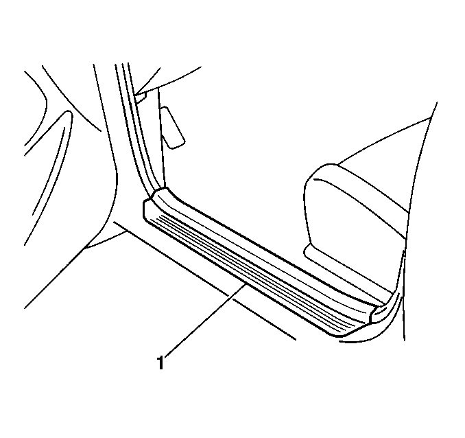
- Unclip and remove the right front side door sill trim plate.
- Remove the front floor front console. Refer to Front Floor Console Replacement in Instrument Panel, Gages and Console.
- Remove the plastic retainer that secures the floor panel carpet to the bulkhead.
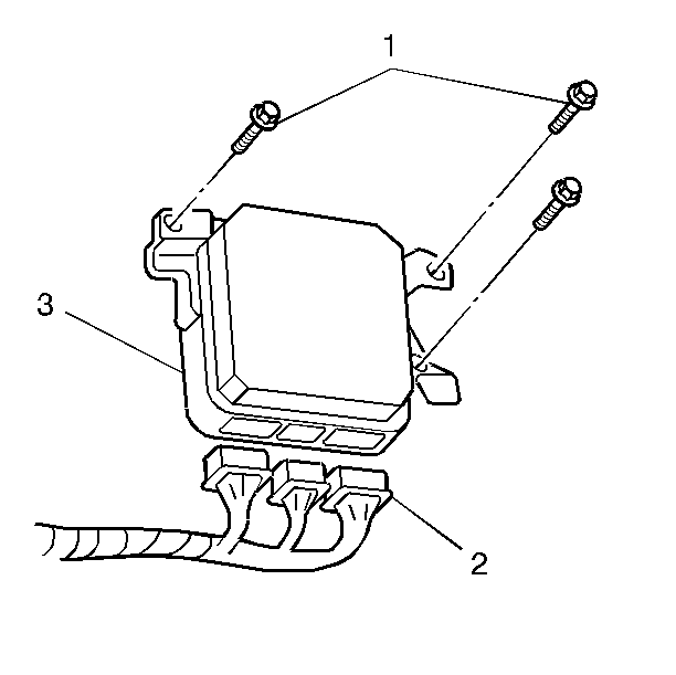
- Remove the 3 bolts (1) that secure the powertrain control module (3).
- Disconnect the 3 PCM electrical connectors (2).
- Remove the powertrain control module (3) from the vehicle.
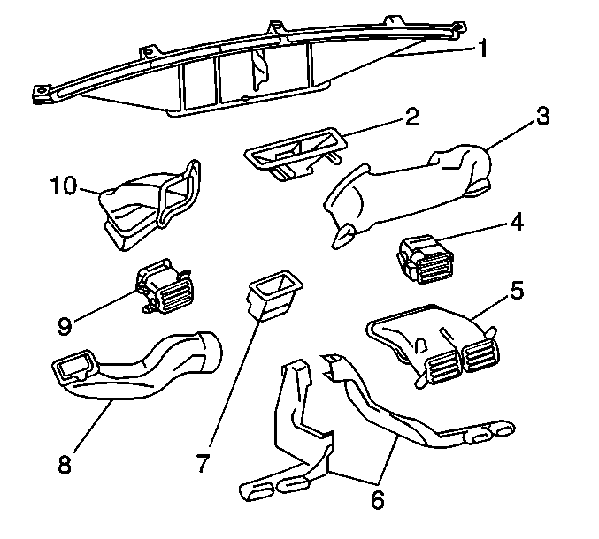
- Remove the 2 plastic retainers (2) that secure the floor panel carpet to the right instrument panel (IP) center support brace (1).
- Position the floor panel carpet back in order to the access the right rear floor air outlet duct.
- Remove the right rear floor air outlet duct (6) from the vehicle.
Installation Procedure
- Install the right rear floor air outlet duct (6) to the vehicle.
- Reposition the floor panel carpet back to its original position.
- Install the 2 plastic retainers (2) that secure the floor panel carpet to the right IP center support brace (1).
- Connect the 3 powertrain control module electrical connectors (2).
- Install the powertrain control module (3) to the vehicle. Secure the module with the 3 bolts (1).
- Install the plastic retainer that secures the floor panel carpet to the bulkhead.
- Install the front floor front console. Refer to Front Floor Console Replacement in Instrument Panel, Gages and Console.
- Install the right front door sill trim plate.
- Install the right body hinge pillar trim panel. Refer to Body Hinge Pillar Trim Panel Replacement in Interior Trim.
Notice: Use the correct fastener in the correct location. Replacement fasteners must be the correct part number for that application. Fasteners requiring replacement or fasteners requiring the use of thread locking compound or sealant are identified in the service procedure. Do not use paints, lubricants, or corrosion inhibitors on fasteners or fastener joint surfaces unless specified. These coatings affect fastener torque and joint clamping force and may damage the fastener. Use the correct tightening sequence and specifications when installing fasteners in order to avoid damage to parts and systems.
Tighten
Tighten the powertrain control module bolts to 15 N·m (11 lb ft).
Floor Air Outlet Replacement Left
Removal Procedure
- Remove the left body hinge pillar trim panel. Refer to Body Hinge Pillar Trim Panel Replacement in Interior Trim.
- Unclip and remove the left front side door sill trim plate (1).
- Remove the following components from the vehicle:
- Remove the front floor front console. Refer to Front Floor Console Replacement in Instrument Panel, Gages and Console.
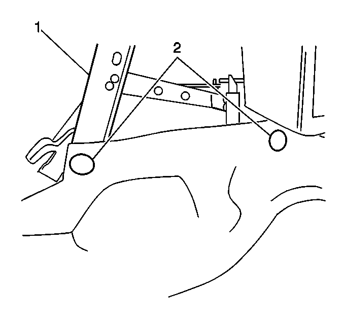
- Remove the plastic retainer (3) that secures the floor panel carpet to the bulkhead.
- Remove the 3 bolts (1) that secure the powertrain control module (3).
- Disconnect the 3 PCM electrical connectors (2).
- Remove the powertrain control module (3) from the vehicle.
- Remove the 2 plastic retainers (2) that secure the floor panel carpet to the left instrument panel (IP) center support brace (1).
- Position the floor panel carpet back in order to the access the left rear floor air outlet duct.
- Remove the left rear floor air outlet duct (6) from the vehicle.
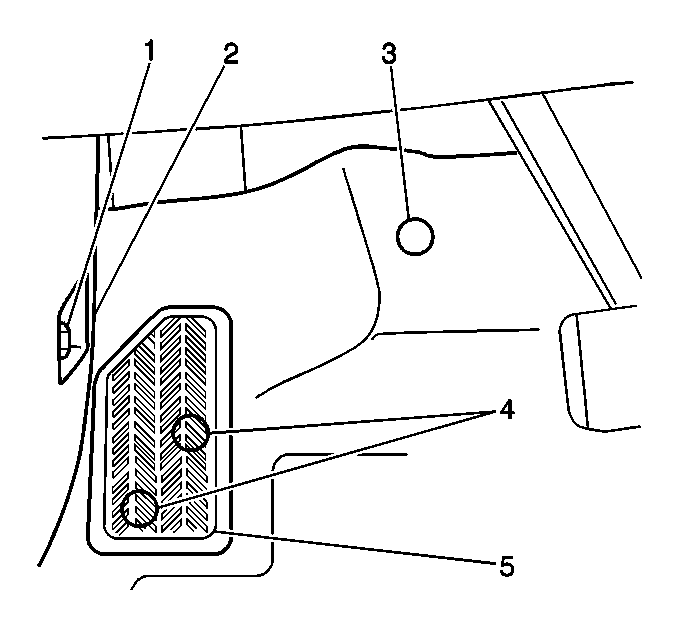
| • | The retainers (4) |
| • | The footrest (5) |
Installation Procedure
- Install the left rear floor air outlet duct (6) to the vehicle.
- Reposition the floor panel carpet back to its original position.
- Install the 2 plastic retainers (2) that secure the floor panel carpet to the left IP center support brace (1).
- Connect the 3 powertrain control module electrical connectors (2).
- Install the powertrain control module (3) to the vehicle. Secure the module with the 3 bolts (1).
- Install the plastic retainer (3) that secures the floor panel carpet to the bulkhead.
- Install the front floor front console. Refer to Front Floor Console Replacement in Instrument Panel, Gages and Console.
- Install the footrest (5) to the vehicle. Secure the footrest with the 2 plastic retainers (4).
- Install the left front side door sill trim plate (1).
- Install the left body hinge pillar trim panel. Refer to Body Hinge Pillar Trim Panel Replacement in Interior Trim.
Notice: Use the correct fastener in the correct location. Replacement fasteners must be the correct part number for that application. Fasteners requiring replacement or fasteners requiring the use of thread locking compound or sealant are identified in the service procedure. Do not use paints, lubricants, or corrosion inhibitors on fasteners or fastener joint surfaces unless specified. These coatings affect fastener torque and joint clamping force and may damage the fastener. Use the correct tightening sequence and specifications when installing fasteners in order to avoid damage to parts and systems.
Tighten
Tighten the powertrain control module bolts to 15 N·m (11 lb ft).
