SERVICE MANUAL UPDATE - SEC. 7 HYDRA-MATIC 4L60 UNIT REPAIR

SUBJECT: ACCUMULATOR ASSEMBLY NEW CALIBRATION
MODEL and YEAR: 1993 CAPRICE, CAMARO AND CORVETTE WITH 2.5L ENGINE 1993 S/T TRUCKS WITH 2.5L ENGINE
TRANSMISSION APPLICATIONS:
1993 HYDRA-MATIC 4L60 (MD8)
TRANSMISSION MODELS:
ALL
SUBJECT: ------- 1993 SECTION 7 HYDRA-MATIC 4L60 TRANSMISSION UNIT REPAIR MANUAL UPDATE - ACCUMULATOR ASSEMBLY
VEHICLE APPLICATIONS:
B, F, Y - CARS S, T - TRUCKS WITH 2.5L
BULLETIN COVERS:
New Product information for 1993 HYDRA-MATIC 4L60 transmissions. This information has been updated since publication of the 1993 Service Manual and should be noted accordingly. Be certain to familiarize yourself with these updates to properly repair the 1993 HYDRA-MATIC 4L60 transmission.
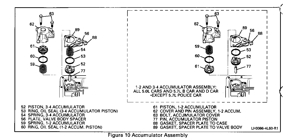
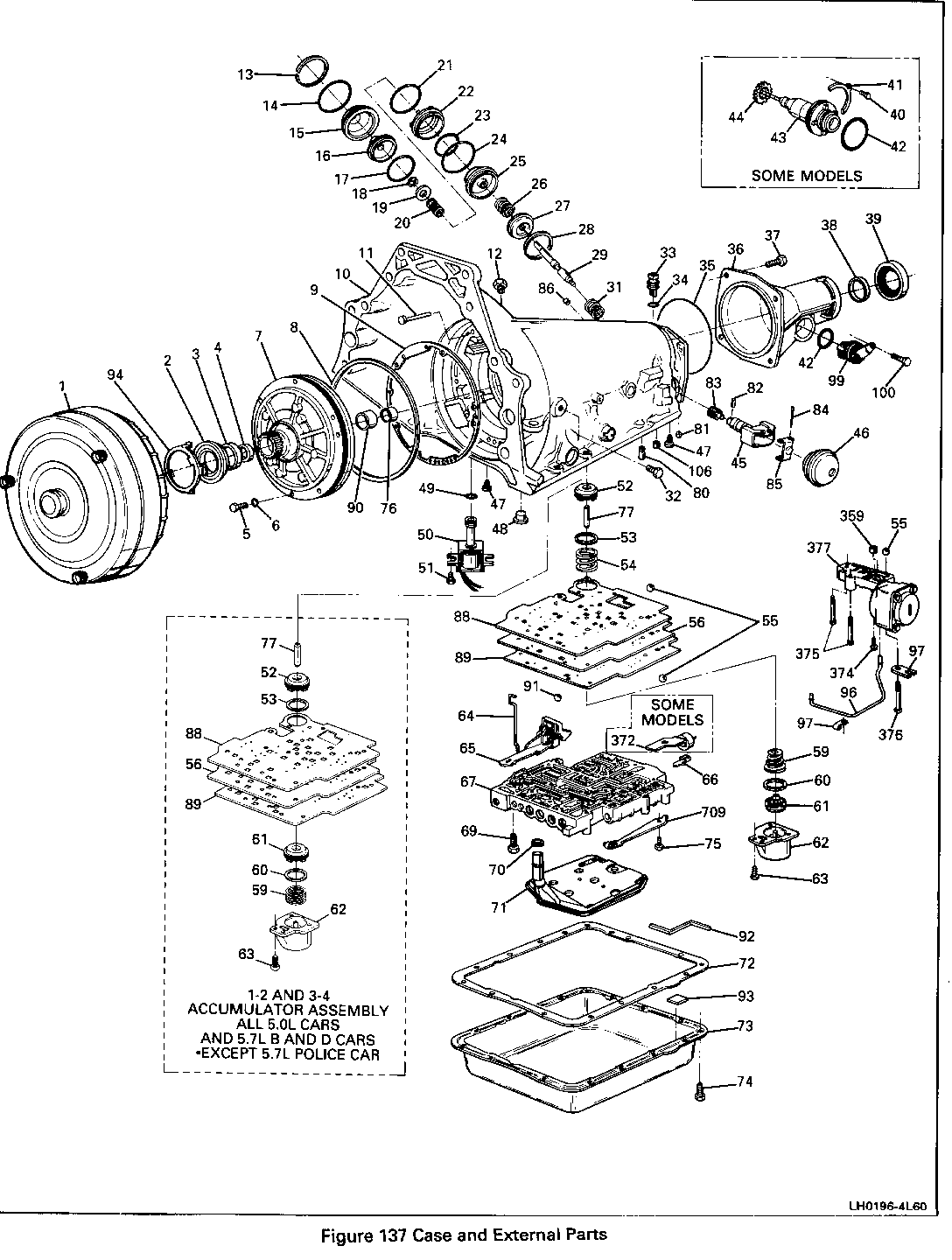
DATE OF PRODUCTION CHANGE: (Figure 1 0) ------------------------- Beginning with Start of Production 1993, HYDRA-MATIC 4L60 transmissions were built with a new calibration that eliminates the 3-4 accumulator spring (III. 54) and inverts the 1-2 accumulator spring (III. 59) with the 1-2 accumulator piston (III. 61).
SERVICE MANUAL REFERENCE:
Update your 1993 Service Manual Section 7A-15B Transmission Unit Repair with the following four (4) pages.
Remove or Disconnect
Figures 9, 11, 12 and 13
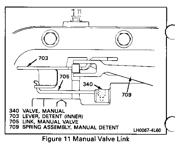
1. Bolt (75) and manual detent spring assembly (709).
2. Electrical wire clips (66).
3. Auxiliary tube clamps (97) and auxiliary accumulator valve tube (96).
4. Wiring hamess retainer washer (A).
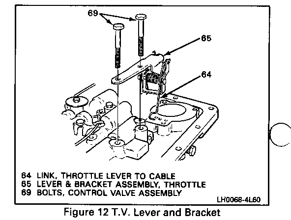
5. Bolts (69) and T.V. lever and bracket assembly (65).
6. T.V. link (64).
Remove or Disconnect
Figures 11 and l3 through 16
1. Remaining valve body bolts (69).
2. Manual valve link (705).
3. Control valve assembly (67).
4. Bolts (374-375), auxiliary valve body (377) and checkball (55B).
5. Spacer plate (56) and spacer plate gaskets (88 and 89).
6. Checkballs (55A, 55C and 91) spring (54), piston (52), seal (53) and pin.
o Three checkballs are located under the valve body: one is in the auxiliary valve body and four are located in the case. The large copper flash colored ball is #10 checkball (91).
o 1-2 accumulator spring (59) and 3-4 accumulator spring (54) for distortion or damage.
o Spacer plate (56) and gaskets (88 and 89) for damage.
o Checkballs (55) for damage.
o T.V. link (64) for damage.
o Manual detent spring (709) for damage.
o Oil filter (71) for:
- Cut or damaged filter seal (70).
- Cracks in the neck or body.
- Casting flash in the neck.
o Solenoid assembly (50) for:
- Damage.
- Cut or pinched wires.
- Damaged connectors.
- Cut or damaged O-ring (49).
Valve Body and Associated Parts
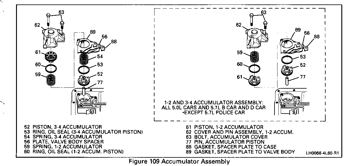
Figures 109 and 111
Tool Required:
J 25025-5 Guide Pins
NOTICE: The use of a honing stone, fine sandpaper or crocus cloth is not recommended for servicing stuck valves. All valve lands have sharply machined corners that are necessary for "cleaning" the bore. If these corners are rounded, foreign material could wedge between the valve and bore causing the valve to stick.
If it is found necessary to clean a valve, "micro fine" lapping compound 900 grit or finer should be used.
Too much "lapping" of a valve will cause excessive clearances and increase the chance of a valve not operating.
3. The 1-2 accumulator piston (61) into the 1-2 accumulator cover and pin assembly (62).
4. The 1-2 accumulator spring (59) onto the piston.
5. The 1-2 accumulator cover and pin assembly (62) onto the case.
o Tighten
o Torque to 11 N-m (98 lb. in.)
Install or Connect
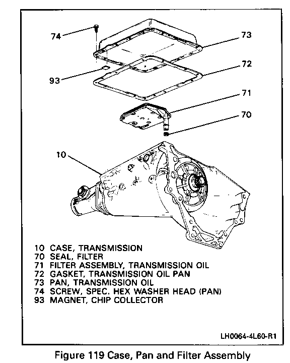
Figure 119
1. Filter seal (70) onto the oil filter.
o Lubricate with TRANSJEL J 36850 or equivalent.
2. Oil filter (71).
3. Oil pan gasket (72).
4. Chip magnet (93) onto oil pan (73).
5. Oil pan (73) and bolts (74).
o Tighten
o Torque to 16 N-m (12 lb. ft.)
2-4 Servo Assembly
Figures 120 through 125
Tools Required:
J 33037 Band Apply Pin Tool
Vernier calipers
Scale
J 22269-01 Piston Compressor
J 29714 Servo Cover Compressor
o Measure
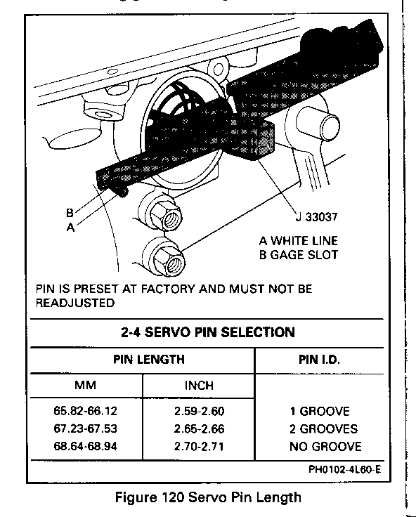
Figure 120
1. Install J 33037 as shown with apply pin (29).
2. Install servo cover retaining ring (13) to secure tool.
3. Apply 11 N-m (98 lb. in.) torque.
4. If white line "A" appears in the gage slot "B", pin length is correct.
5. Use pin selection chart to determine the correct pin length if new pin is needed.
o Inspect
o Pistons for:
- Porosity or damage.
- Ring groove damage.
General Motors bulletins are intended for use by professional technicians, not a "do-it-yourselfer". They are written to inform those technicians of conditions that may occur on some vehicles, or to provide information that could assist in the proper service of a vehicle. Properly trained technicians have the equipment, tools, safety instructions and know-how to do a job properly and safely. If a condition is described, do not assume that the bulletin applies to your vehicle, or that your vehicle will have that condition. See a General Motors dealer servicing your brand of General Motors vehicle for information on whether your vehicle may benefit from the information.
