Product Safety - Charge Port Assembly

| Subject: | 00025A -- Charge Port Assembly |
| Models: | 1997-1998 Chevrolet S-10 Electric Trucks |
Condition
General Motors has decided that a defect which relates to motor vehicle safety exists in all 1997-1998 Chevrolet S-10 electric trucks. These vehicles were produced with a charge port assembly that may fail during a charging event. If this occurs, heat could build up within the charge port and a vehicle fire could result without prior warning. Persons could suffer burn injuries and property could be damaged.
Correction
Most of these vehicles were shipped back to General Motors in March 2000 for maintenance of the batteries. As parts become available over the next three months, General Motors will ship these vehicles back to the responsible dealer. When dealers receive a vehicle, they are to replace the charge port assembly with a redesigned charge port assembly. When the correction has been performed, dealers are to wash the vehicle, and then contact the customer to arrange for pickup/delivery of the vehicle.
Vehicles Involved
Involved are all 1997-1998 Chevrolet S-10 electric trucks built within these VIN breakpoints:
Year | Division | Model | Plant | From | Through |
|---|---|---|---|---|---|
1997 | Chevrolet | S-10E | Shreveport | W8154854 | W8209178 |
1998 | Chevrolet | S-10E | Shreveport | W8100399 | W8217661 |
Important: Dealers should confirm vehicle eligibility through GMVIS (GM Vehicle Inquiry System) before beginning campaign repairs. [Not all vehicles within the above breakpoints may be involved.]
Involved vehicles have been identified by Vehicle Identification Number. Computer listings containing the complete Vehicle Identification Number, customer name and address data have been prepared, and are being furnished to involved dealers with the campaign bulletin. The customer name and address data furnished will enable dealers to follow-up with customers involved in this campaign. Any dealer not receiving a computer listing with the campaign bulletin has no involved vehicles currently assigned.
These dealer listings may contain customer names and addresses obtained from Motor Vehicle Registration Records. The use of such motor vehicle registration data for any other purpose is a violation of law in several states/provinces/countries. Accordingly, you are urged to limit the use of this listing to the follow-up necessary to complete this campaign.
Parts Information
Parts required to complete this campaign are to be obtained from General Motors Service Parts Operations (GMSPO). Please refer to your "involved vehicles listing" before ordering parts. Normal orders should be placed on a DRO = Daily Replenishment Order. In an emergency situation, parts should be ordered on a CSO = Customer Special Order.
Part Number | Description | Qty/ Vehicle |
|---|---|---|
*88880044 | Receptacle Kit, Drv Mot Bat Charger | 1 |
12378390 | Coolant, Electracool (one gallon will service 2 vehicles) | 1/2 Gallon |
*Due to the small number of vehicles involved and due to limited initial parts availability, GM will ship vehicles back to dealerships on a weekly basis over approximately a 12 week period. Dealers are encouraged not to order campaign parts for use a shelf stock. Parts should only be ordered when vehicle arrive at your dealership.
Service Procedure
Important: DO NOT perform this campaign on 1997 and 1998 vehicles with the lead acid (TP0) battery packs. This campaign is to be completed on vehicles with high capacity lead acid (TP6) or nickel-metal hydride (TP1) battery packs only.
If the 1997 and 1998 vehicle is equipped with the original TP0 batteries, the battery pack should be upgraded to the TP6 batteries and configuration. Refer to the Chevrolet Special Policy Service Bulletin 99022, and also the General Motors Service Parts Operations Special Policy Bulletin on battery pack conversion 99-1. To determine if the battery pack is the TP0 type, perform the following quick checks with the Tech 2 scan tool:- Diagnostics
- Model Year
- Ld. Truck
- Powertrain
- Electric Motor LN-1
- Data Display
- BPCM Data Display
- BPCM Battery Temperature Sensors
| - | Technology Resistor Voltage |
| - | If the Technology Resistor Voltage value is less than 0.7 volts, or greater than 1.5 volts, perform the service procedure outlined in the Chevrolet Special Policy Bulletin 99022. When you have completed performing the procedure in bulletin 99022, perform this campaign procedure. |
- Position the vehicle over a hoist so it can be lifted.
- Open the hood and install seat and fender covers.
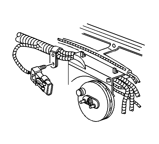
- Remove the "Service Disconnect Connector" jumper from the end of the wiring harness, located just to the right of the power brake booster.
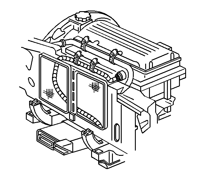
- Disconnect the charge receptacle high voltage cable from the power inverter module. Refer to Figure 2.
- Carefully and slowly, loosen the cap from the round coolant reservoir to allow any internal pressure to escape. Do not remove the cap.
- Raise the vehicle.
- Remove the lower metal shield from behind the front bumper to the core support.
- Place a clean receptacle under the vehicle to accept the Electracool as it is drained from the vehicle.
- Place the hose clamping tools on each of the coolant hoses about 2 inches above the charge port nipples.
- Loosen the hose clamps and disconnect both hoses from the charge port.
- Remove the hose clamping tool only from the hose on the right (passenger) side of the charge port and drain the coolant into the container.
- Disconnect the 8-way electrical connector from the charge receptacle.
- Remove the two (2) 10mm bolts retaining the charge port to the front bumper reinforcement.
- Remove the two (2) 10mm bolts, which retain the charge port rear bracket to the frame.
- Remove the charge port assembly from the vehicle.
- Remove the rear bracket from the old charge port assembly.
- Remove the new charge port from the shipping container.
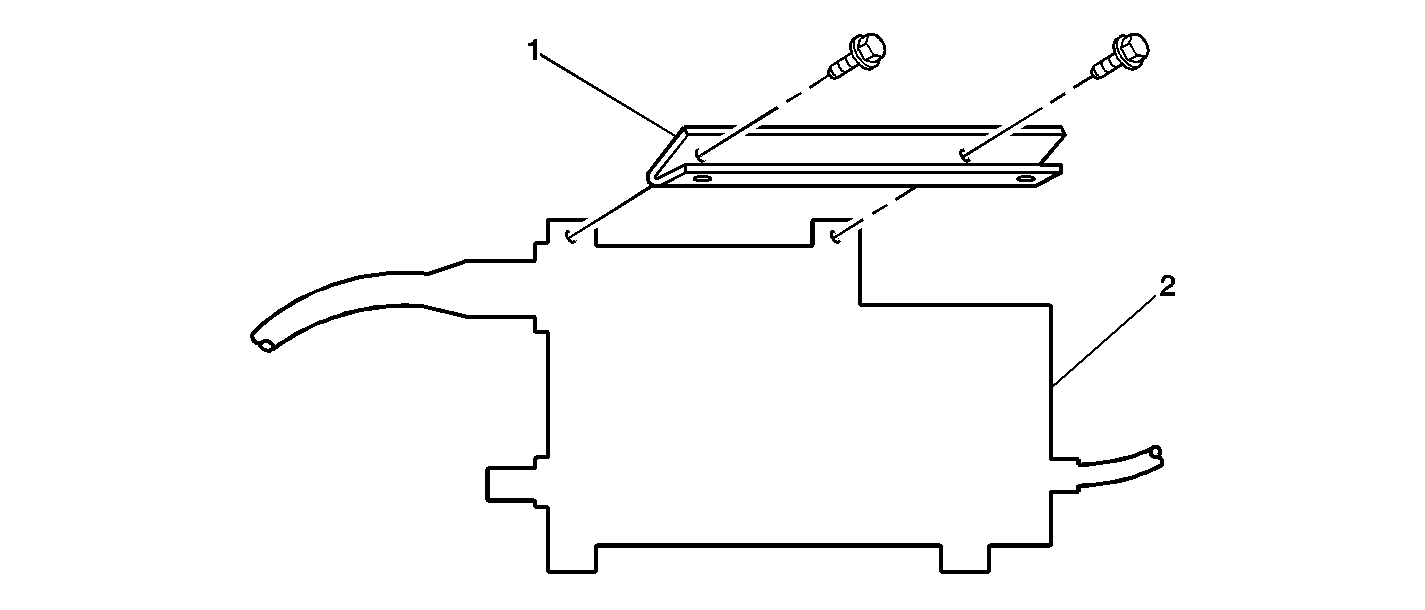
- Position the charge port interface unit (2) on the bench with the control module cable on the left side. Position the new short L-shaped bracket (1) to the charge port interface so that the opening of the "L" is facing away from you, and install two screws which have the small washers.
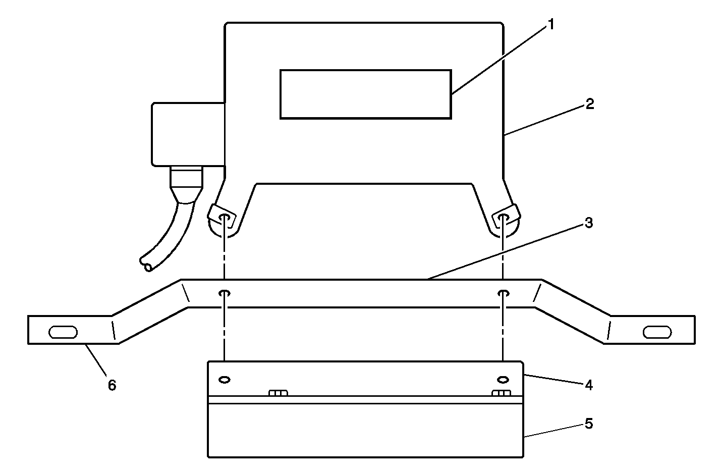
- With the charge port (2) resting on the bench, caution label (1) up, and the charge port opening away from you, position the old bracket (6) , removed in Step 16, to the charge port so that the part number (3) on the bracket (6) is in the correct orientation for reading of the numbers. Fold the charge port interface cable, and position the interface unit (5) so that is hangs down from the attachment to the charge port. Insert two screws with small washers to hold the assembly together. Do not tighten completely. This will allow proper positioning in the vehicle.
- Assemble the new long angle bracket to the charge port interface.
- Install the rose bud clip on the interface cable, into the hole in the center of the new long angle bracket.
- Position the assembly so that the large GM label is facing up and is in the correct orientation for reading.
- Install the hose clamps to the S-shaped hose. Install the hose between the charge port interface unit (5) and the charge port (2). Route the hose form the left end of the interface unit to the top port on the charge port and properly position the clamps.
- Install the completed assembly to the vehicle, starting with the original rear-mounting bracket. Loosely install the retainers.
- Install the front charge port assembly bolts.
- Properly align the new rear-mounting bracket, just to the rear of the old mounting bracket.
- Tighten the fasteners that hold the assembly to the frame, into the original mounting holes and the fasteners of Step 19.
- Drill a 10mm (13/32 in) hole into the frame after the new mounting bracket is properly positioned, using the holes in the bracket as a guide.
- Install the two J-clips into the frame cut out and over the newly drilled holes.
- Install the retainers through the bracket and into the newly installed J-clips.
- Route the new long hose to the top of the motor following the route of the old hose. Install a hose clamps on the hose and install the hose to the charge port.
- Connect the original left side coolant hose to the charge port and properly position the clamp.
- Remove the hose clamping tool from the left side hose.
- Route the charge port high voltage cable up to the motor following the original routing as closely as possible.
- Remove and save the plug from cavity F of the vehicle's 8-way wiring harness connector.
- Remove the terminal from cavity B (green wire) of the vehicle's 8-way wiring harness connector, and place it in cavity F of the 8-way wiring harness connector.
- Install the plug removed in Step 35 above, into the B cavity of the 8-way wiring harness connector.
- Route the 8-way harness over the bracket, connect the 8-way connectors together and place the retaining tab in the hole provided on the bracket.
- Lower the vehicle.
- Install the high voltage cable to the drive motor inverter module and install new tie straps.
- Remove the original coolant hose from the "T" of the coolant crossover hose/pipe. Install a hose clamp to the new hose. Connect the new hose to the "T" and properly position the clamp.
- Remove the cap from the round coolant reservoir and refill with new Electracool coolant to the cold maximum line on the reservoir.
- Install the "Service Disconnect Connector."
- Turn the key to the ON position.
- Raise the vehicle and inspect the lower hoses for leaks. Repair if necessary.
- Install the metal deflector panel.
- Lower the vehicle.
- Inspect the "T" of the upper coolant hose crossover for leaks.
- Ensure that the coolant level is between the cold minimum indicator line and the cold maximum indicator line on the round coolant bottle.
- Reprogram the Battery Pack Control Module and Drive Motor Control Module with the update found on TIS 2000, CD #17 or newer.
- After the BPCM and DMCM are reprogrammed, the leveling "bit" must be set to ensure accurate results from the battery pack discharge test. Select the following menus on the Tech 2:
- With the batteries installed in the vehicle, charge the vehicle batteries until the charger display shows "Full/Complete". When "Full/Complete" is displayed, go to the next step. If "Full/Complete" cannot be obtained, use the Tech 2 and scan for diagnostic trouble codes (DTC). If a DTC is displayed, go to the applicable DTC chart in the service information manual for repair instructions.
- Perform the Battery Pack Discharge Test as outlined in the chart found at the end of this procedure.
- Install the GM Campaign Identification Label.
- Complete the following checklist and repair as necessary:
Figure 1

Caution: In order to prevent personal injury, complete the High Voltage Disable Procedure when working on or around any high voltage and before any of the repair procedures.
Figure 2

If the high voltage cable is held in place with cable ties, clip them, and route the cable to the bottom of the motor compartment.
Caution: In order to help avoid being burned, do not remove the radiator cap while the engine and the radiator are hot. Scalding fluid and steam can be blown out under pressure if the cap is removed too soon.

Important: The charge port interface is the unit without the large opening for the charger paddle.
Tighten
Tighten the screws to 10 N·m (89 lb in).

Tighten
Tighten to 10 N·m (89 lb in).
Tighten
Tighten the bolts to 10 N·m (89 lb in).
Tighten
Tighten to 10 N·m (89 lb in).
Tighten
Tighten to 10 N·m (89 lb in).
| 51.1. | Diagnostics |
| 51.2. | Model Year |
| 51.3. | Ld. Truck |
| 51.4. | Powertrain |
| 51.5. | Electric Motor LN-1 |
| 51.6. | Special Functions |
| 51.7. | Initiate Leveling |
The Tech 2 will display a screen with the criteria to initiate leveling. Follow the onscreen instructions, Key On, Vehicle Off Charge, select Enter.
| • | Proper head lamp operation |
| • | Brake lamp operation |
| • | Turn signal/emergency lamp operation |
| • | Seat belt operation |
| • | Windshield wiper/washer operation |
| • | Tire pressure (50 psi) |
| • | Horn operation |
| • | Cabin heating and air conditioning operation |
| • | Fluid levels (brake, power steering, both coolant reservoirs, washer solvent) |
| • | Road test. Check vehicle for proper operation of all systems, including the service and park brake system, and that no warning/indicator lamps illuminate. |
| • | Wash the vehicle exterior. |
Step | Action | Value | Yes | No | ||||||
|---|---|---|---|---|---|---|---|---|---|---|
1 |
Important: Before connecting the batter pack pre-charge/discharge tester, always make sure the switch is in the OFF position. Are all steps completed? | -- | Go to Step 2 | -- | ||||||
2 |
Caution: In order to prevent personal injury, do not touch or place any object on the surface of the J 42680-2 battery pack discharge tool when in use. The surface temperature can exceed 149°C (300°F). Important: The scan tool will automatically open the high voltage relays and conclude
the test when the battery pack has reached the following:
Did the test terminate before the specified amp hour values were reached? | 48.0 amp hours for the TP-6 high capacity lead acid battery, or 68.8 amp hours (NiMH) battery | Go to Step 3 | Go to Step 4 | ||||||
3 |
Is the repair action complete? | -- | Go to Step 1 and retest | -- | ||||||
4 | Using the scan tool, review the results of the test. Are any battery module(s) identified as needing replacement? | -- | Go to Step 3 | Go to Step 5 | ||||||
5 |
Caution: In order to prevent personal injury, do not touch or place any object on the surface of the J 42680-1 battery pack discharge resistor bank tool when in use. The surface temperature can exceed 149°C (300°F). Important: Before disconnecting the battery pack pre-charge/discharge tester, always make sure the switch is in the OFF position. Recharge the batteries until "Complete" is displayed. | -- | -- | -- |
Campaign Identification Label
Place a Campaign Identification Label on each vehicle corrected in accordance with the instructions outlined in this Product Campaign Bulletin. Each label provides a space to include the campaign number and the five (5) digit dealer code of the dealer performing the campaign service. This information may be inserted with a typewriter or a ball point pen.
Put the Campaign Identification Label on a clean and dry surface of the radiator core support in an area that will be visible to people servicing the vehicle. When installing the Campaign Identification Label, be sure to pull the tab to allow the adhesion of the clear protective covering. Additional Campaign Identification Labels for US dealers can be obtained from Dealer Support Material by calling 1-888-549-6152 (Monday-Friday, 8:00 am to 5:00 pm EST). Ask for Item Number S-1015 when ordering.
Claim Information
Submit a Product Campaign Claim with the information indicated below:
Repair Performed | Part Count | Part No. | Parts Allow | CC-FC | Labor Op | Labor Hours* | Net Item |
|---|---|---|---|---|---|---|---|
Install Charge Port Asm | 1 | -- | ** | MA-96 | V0487 | 4.3 | *** |
* -- For Campaign Administrative Allowance, add 0.1 hours to the "Labor Hours". ** -- The "Parts Allowance" should be the sum total of the current GMSPO Dealer net price plus applicable Mark-Up or Landed Cost Mark-Up (for IPC) for receptacle kit needed to complete the repair. *** -- The amount identified in the "Net Item" column should represent the sum total of the Current GMSPO net price plus applicable Mark-Up or Landed Cost Mark-Up (for IPC) for the coolant/fluids needed to perform the required repairs and the actual cost to wash the vehicle. | |||||||
Refer to the General Motors WINS Claims Processing Manual for details on Product Campaign Claim Submission.
Customer Notification
General Motors initially notified customers, by telephone and then by letter, of this campaign on their vehicle in March, 2000. General Motors requested customers to allow arrangements to be made to return their vehicle to a GM facility so that the vehicle battery packs could be maintained under controlled conditions during the redesign of the charge port assembly. General Motors will now begin notifying customers that a redesigned charge port assembly is currently available. For customers whose vehicles were stored at a GM facility, they will be informed that their dealer will contact them by telephone when the repair has been completed and arrangements will be made for the return of their vehicle (see copy of this customer letter included with this bulletin).
Dealer Campaign Responsibility
The US National Traffic and Motor Vehicle Safety Act provides that each vehicle which is subject to a recall campaign of this type must be adequately repaired within a reasonable time after the customer has tendered it for repair. A failure to repair within sixty days after tender of a vehicle is prima facie evidence of failure to repair within a reasonable time. If the condition is not adequately repaired within a reasonable time, the customer may be entitled to an identical or reasonably equivalent vehicle at no charge or to a refund of the purchase price less a reasonable allowance for depreciation. To avoid having to provide these burdensome remedies, every effort must be made to promptly schedule an appointment with each customer and to repair their vehicle as soon as possible. In the recall campaign notification letters, customers are told how to contact the US National Highway Traffic Safety Administration if the campaign is not completed within a reasonable time.
All unsold new vehicles in dealers' possession and subject to this campaign MUST be held and inspected/repaired per the service procedure of this campaign bulletin BEFORE customers take possession of these vehicles.
Dealers are to service all vehicles subject to this campaign at no charge to customers, regardless of mileage, age of vehicle, or ownership, from this time forward.
Customers who have recently purchased vehicles sold from your vehicle inventory, and for which there is no customer information indicated on the dealer listing, are to be contacted by the dealer. Arrangements are to be made to make the required correction according to the instructions contained in this bulletin. This could be done by mailing to such customers a copy of the customer letter accompanying this bulletin. Campaign follow-up cards should not be used for this purpose, since the customer may not as yet have received the notification letter.
In summary, whenever a vehicle subject to this campaign enters your vehicle inventory, or is in your dealership for service in the future, please take the steps necessary to be sure the campaign correction has been made before selling or releasing the vehicle.
October, 2000Dear Chevrolet Customer:
This notice is sent to you in accordance with the requirements of the National Traffic and Motor Vehicle Safety Act.
Earlier this year you may have been contacted by Chevrolet Motor Division about modifications needed to the charge port assembly of your S-10 electric truck. At that time you were asked to park your vehicle and discontinue all vehicle charging until the parts for the modification were available. This letter is to inform you that parts are now available to correct your charge port assembly.
Reason For This Recall
General Motors has decided that a defect which relates to motor vehicle safety exists in all 1997-1998 Chevrolet S-10 electric trucks. These vehicles were produced with a charge port assembly that may fail during a charging event. If this occurs, heat could build up within the charge port and a vehicle fire could result without prior warning. Persons could suffer burn injuries and property could be damaged.
What Will Be Done
Your Chevrolet dealer will replace the charge port assembly with a redesigned charge port assembly. This service will be performed for you at no charge .
If your vehicle was shipped back to General Motors for maintenance of the battery pack, it will be shipped back to your dealer for the necessary correction. When the correction has been performed, your dealer will contact you to arrange for delivery of your vehicle. Due to parts availability, it may take up to approximately 12 weeks before your dealer contacts you.
How Long Will The Repair Take?
The length of time required to perform this service correction is approximately 1/2 half a day to complete the repairs with an additional day for discharging and charging the battery pack. Additional time may be required to schedule and process your vehicle. If you dealer has a large number of vehicles awaiting service, this additional time may be significant. Please ask your dealer if you wish to know how much additional time will be needed to schedule, process and repair your vehicle.
Contacting Your Dealer
If your vehicle was shipped back to General Motors, there is no need for you to contact your dealer. Your dealer will contact you when your dealer has performed the necessary correction. If you are still driving your vehicle, contact your Chevrolet dealer as soon as possible to arrange a service date. Parts are available and instructions for making this correction have been sent to your dealer.
Your Chevrolet dealer is best equipped to obtain parts and provide services to correct your vehicle as promptly as possible. Should your dealer be unable to schedule a service date within a reasonable time, you should contact the appropriate Customer Assistance Center at the number listed below:
Division | Number | Deaf, Hearing Impaired, or Speech Impaired* |
|---|---|---|
Chevrolet | 1-800-222-1020 | 1-800-833-2438 |
* Utilizes Telecommunication Devices for the Deaf/Text Telephones (TDD/TTY) | ||
If, after contacting the appropriate customer assistance center, you are still not satisfied that we have done our best to remedy this condition without charge and within a reasonable time, you may wish to write the Administrator, National Highway Traffic Safety Administration, 400 Seventh Street SW, Washington, DC 20590 or call 1-888-327-4236.
Courtesy Transportation
Earlier this year you were offered the use of an Enterprise rental vehicle until your vehicle was repaired. If you took advantage of this offer, contact your renting Enterprise branch office to make arrangements for the return of your rental when your dealer informs you that the necessary repairs have been made to your vehicle.
Customer Reply Card
The attached customer reply card identifies your vehicle. Presentation of this card to your dealer will assist in making the necessary correction in the shortest possible time. If you no longer own this vehicle, please let us know by completing the attached and mailing it in the postage paid envelope.
We are sorry to cause you this inconvenience; however, we have taken this action in the interest of your safety and continued satisfaction with our products.
Chevrolet Motor Division
General Motors Corporation
Enclosure
