Check Vehicle Message Displayed on Charger, Battery Pack Control Module DTC 267 Set (Replace and Relocate Airflow Sensor)

| Subject: | Check Vehicle Message Displayed on Charger, Battery Pack Control Module DTC 267 Set (Replace and Relocate Airflow Sensor) |
| Models: | 1997-1998 Chevrolet S-10 Electric Trucks |
| With Lead-Acid or NiMH Battery Packs |
Condition
Some customers may comment that the vehicle will accept a charge for several minutes and then stop. A "Check Vehicle" message may be displayed on the charger. A check of DTCs may show a Battery Pack Control Module DTC 267 in current or in history.
Cause
An airflow sensor degradation due to water intrusion may cause this condition.
Correction
Relocate the airflow sensor using the following service procedure. The service kit contains the necessary parts to relocate the airflow sensor to the top of the Battery Thermal Module.
- Remove the High Voltage Disconnect connector under the hood.
- Raise the vehicle.
- Remove two nuts from under the skid plate.
- Remove the two bolts and nuts that attach the skid plate to the battery pack.
- Remove the five bolts that retain the skid plate to the bottom of the vehicle and remove the skid plate.
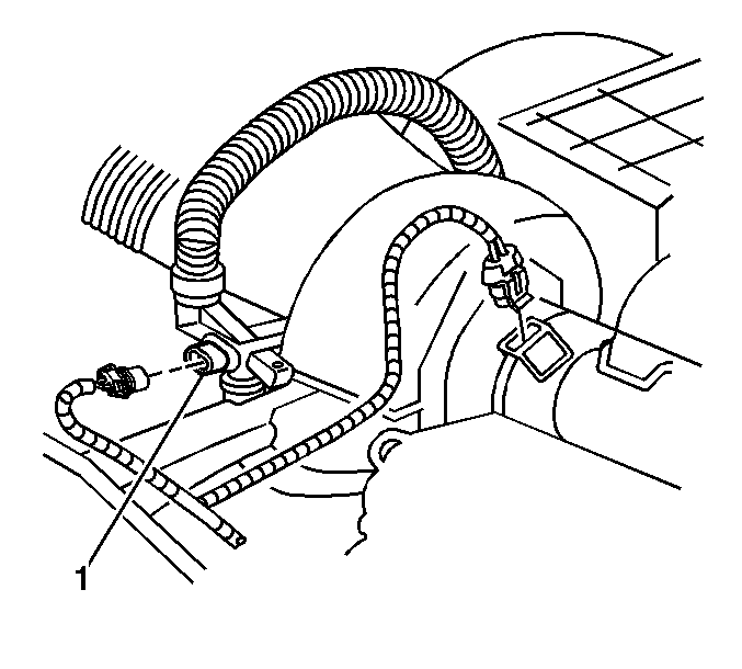
- Disconnect the electrical connector (1) from the airflow sensor.
- Loosen the hose clamp from the lower airflow sensor hose connection at the Blower Thermal Module (BTM). The clamp can be left on the hose.
- Remove the ¼ in screw from the lower hose connection at the BTM.
- Disconnect the hose from the BTM.
- Loosen the hose clamp from upper hose connection at the airflow sensor. The clamp can be left on the hose.
- Remove the ¼ in screw from the upper hose connection at the airflow sensor.
- Disconnect the hose from the upper hose connection at the old airflow sensor.
- Grasp the hose at the uppermost point and pull down until sufficient room is available to install the new airflow sensor (T) into the hose.
- Measure and mark the hose 63 mm (2.5 in) from the end that was connected to the upper connection at the airflow sensor.
- Cut the hose at the point marked.
- Install a clamp to each end of the newly cut hose and insert the "T" into the hose ends. Leave the hose clamps loose so the hoses and "T" assembly can be properly aligned.
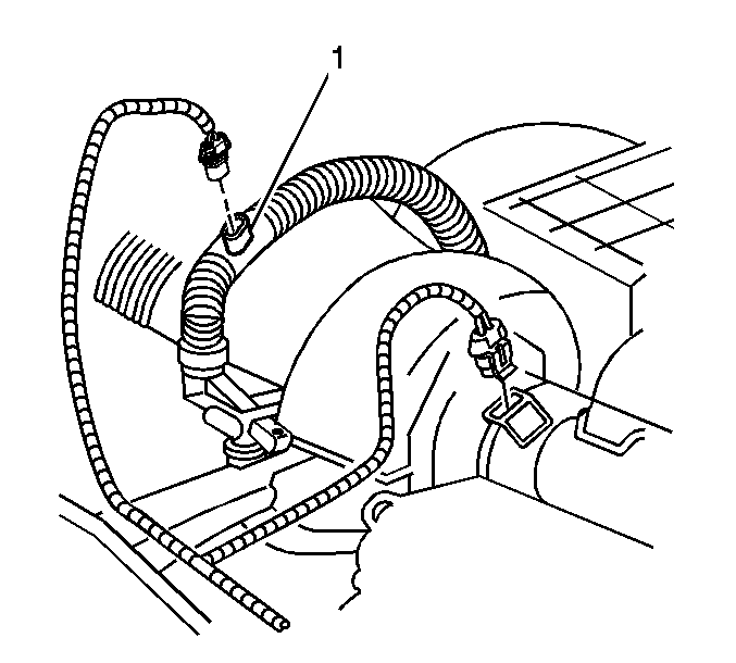
- Grasp the lower hose and pull until the "T" is at the top of the BTM.
- Connect the hose at the bottom of the BTM.
- Install the ¼ in screw to the lower connection at the BTM.
- Tighten the hose clamp at the lower connection.
- Connect the hose at the top of the old airflow sensor.
- Install the ¼ in screw to upper connection at the old airflow sensor.
- Tighten the hose clamp at the old airflow sensor.
- Position the "T" so the airflow sensor points toward the front of the truck.
- Tighten all hose clamps.
- Inspect the airflow electrical connector for corrosion and/or damage. If damage is present, replace the connector with the new one provided in the kit. Follow the directions provided in the kit for proper installation of the new connector.
- Connect the electrical connector to the new airflow sensor.
- Leave the old airflow sensor in place and use RTV to fill in the old airflow sensor electrical connector cavity. This prevents the harness from being re-connected to the old airflow sensor in the future.
- Install the skid plate and the five retaining bolts.
- Install the two bolts and nuts attaching the skid plate to the battery pack.
- Install the two nuts to the skid plate.
- Lower the vehicle.
- Install the High Voltage Disconnect under the hood.
- Place the vehicle on Charge and, using a scan tool, verify proper airflow.


Tighten
Tighten the bolts to 50 N·m (37 lb ft).
Tighten
Tighten to 75 N·m (55 lb ft).
Tighten
Tighten the nuts to 5 N·m (44 lb in).
Parts Information
Part Number | Description | Qty |
|---|---|---|
27005744 | Kit Asm, Airflow Sensor | 1 |
Parts are currently available from GMSPO.
Warranty Information
For vehicles repaired under warranty, use:
Labor Operation | Description | Labor Time |
|---|---|---|
D2127 | Sensor, Battery Thermal Module Air-flow-Replace | 0.8 hr |
Add | If necessary to replace wiring connector | 0.2 hr |
