Tools Required OLD
J 39200 Digital Multimeter
An undercharged battery is usually characterized by slow cranking or
by a dark battery hydrometer. If this condition exists, check the following
items for a cause.
- Determine that the undercharged condition has not been caused
by leaving accessories on for extended periods without charging the battery.
- Check the drive belt for proper tension. Refer to
Generator Replacement
in this section.
- If battery fault is suspected, refer to
Battery Common Causes of Malfunction
in this section.
- Inspect the wiring for faults. Check that all connections are
clean and tight. Also check that all bulkhead connectors are tight and undamaged.
Battery cable connections at the battery, starter and engine ground points
should also be checked.

- With all accessories turned
off, connect a J 39200
across the battery. Run the engine at a moderate speed and check the voltage,
taking into account the temperature the generator is exposed to during the
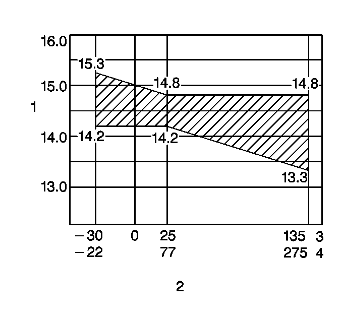
test. As the temperature of the regulator case (2) in the generator increases,
the voltage output will decrease. The standard regulator voltage setting
(1) is 14.2 to 14.8 volts at 25°C (3) (77°F (4)). The minimum operating
voltage should be 13.5 volts. If the voltage is at 13.5 volts or more, proceed
to the next step. If the voltage is less than 13.5 volts, remove the generator.
Refer to
Generator Replacement
.
- If the previous steps have not produced satisfactory results,
perform the following generator test.
| 6.1. | Disconnect the negative (-) battery cable. |
| 6.2. | Remove the rubber protector, the nut and the generator battery
terminal wire. |

| 6.3. | Connect an ammeter (1) between the generator (2) and the disconnected
wire. Connect the ammeter black lead to the wire and the ammeter red lead
to the generator battery terminal. |
Connect a J 39200
between
the generator battery terminal and the chassis ground.
| 6.4. | Start and run the engine at 2,000 RPM. Turn all accessories and
high-beam headlamps on. Turn the blower to HIGH. Ground the generator F terminal
with a screwdriver. |
| 6.5. | Adjust the engine speed to obtain the maximum current output. |
| 6.6. | If the current output is within 10 amperes of the maximum rating
and the voltage reading is 13.5 to 16.0 volts, the generator is not faulty
and is not the cause of an undercharged battery condition. If the current
output is not within 10 amperes of the maximum rating, or the voltage reading
is less than 13.5 volts, remove the generator. Refer to
Generator Replacement
or
Generator Overhaul
. |
If an obvious overcharge condition exists (as evidenced by spewing of
electrolyte), test the field windings for shorts and grounds. If the field
winding is faulty, replace the rotor and retest the generator for proper
voltage output. Refer to
Generator Replacement
or
Generator Overhaul
.
On Vehicle Voltage Regulator Test
- Connect a fast charger and a J 39200
to the battery.
- Turn the ignition switch to ON and slowly increase the charge
rate. The indicator in the vehicle will begin to dim when the voltage setting
is reached. The indicator should dim at 13.5 to 16.0 volts. If the test
results are unsatisfactory, replace the voltage regulator. Refer to
Generator Replacement
or
Generator Overhaul
.
Off Vehicle Voltage Regulator Test
- Remove the generator from the vehicle. Refer to
- Remove the voltage regulator from the generator. Refer to
- Connect a J 39200
and a fast charger to a fully charged 12 volt battery.
- Connect the voltage regulator battery terminal to the battery
positive terminal.
- Connect a test lamp across the voltage regulator rotor terminals.
If the test lamp lights, proceed to the next step. If the test lamp does
not light, replace the voltage regulator.
- Turn the fast charger on. Observe the J 39200
. The test lamp will begin to dim as the voltage regulator setting is reached.
The test lamp should go out at 13.5 to 16.0 volts. If the test
results are satisfactory, the voltage regulator is serviceable and should
be reinstalled on the vehicle. If the test results are unsatisfactory,
replace the voltage regulator.
The test lamp is connected into the circuit exactly as the rotor would
be when the regulator is inside the generator. The regulator interrupts the
current to the test lamp when the regulator voltage setting is reached.
This voltage will vary slightly with temperature variations.


