Notice: To prevent damage to the cylinder block or parts installed:
| • | All parts to be installed must be perfectly clean. |
| • | Be sure to apply engine oil to the crankshaft journals, journal
bearings, thrust bearings, crankpins, connecting rod bearings, pistons, piston
rings and cylinder bores. |
| • | Journal bearings, bearing caps, connecting rod, rod bearings,
rod bearing caps, pistons and piston rings are in combination sets. Do not
disturb the combinations and check to ensure that each part goes back to where
it came from when installing. |
- Install the main bearings lower half to the crankshaft: Install the
half with the oil groove (upper half) to the cylinder block.
- Install the thrust bearings to the cylinder block between the
number 2 and number 3 cylinders. Face the oil groove sides to the counterweights.
- Install the crankshaft to the cylinder block.
Important: On each main bearing cap, the arrow mark and number are embossed. When
installing each main bearing cap to the cylinder block, point the arrow mark
toward the crankshaft pulley side and install each cap from the crankshaft
pulley end to the flywheel in order 1, 2, 3, 4 and 5.
- Install the five main bearing caps and two bearing cap supports.
Notice: Use the correct fastener in the correct location. Replacement fasteners
must be the correct part number for that application. Fasteners requiring
replacement or fasteners requiring the use of thread locking compound or sealant
are identified in the service procedure. Do not use paints, lubricants, or
corrosion inhibitors on fasteners or fastener joint surfaces unless specified.
These coatings affect fastener torque and joint clamping force and may damage
the fastener. Use the correct tightening sequence and specifications when
installing fasteners in order to avoid damage to parts and systems.
Important:
| • | Gradual and uniform tightening is important for main bearing cap
bolts. |
| • | After tightening the main bearing bolts, check to ensure that
the crankshaft rotates smoothly when turned by hand. |
- Secure with the ten main bearing cap bolts.
Tighten
Tighten the main bearing cap bolts to 54 N·m (40 lb ft).
- Apply a light coat of clean engine oil to the following:
| • | The connecting rod bearings |
- Install the guide hoses over the connecting rod
bolts in order to prevent damage to the bearing journal and the connecting
rod bolt threads when installing the connecting rods.
- Use a J 8037
in
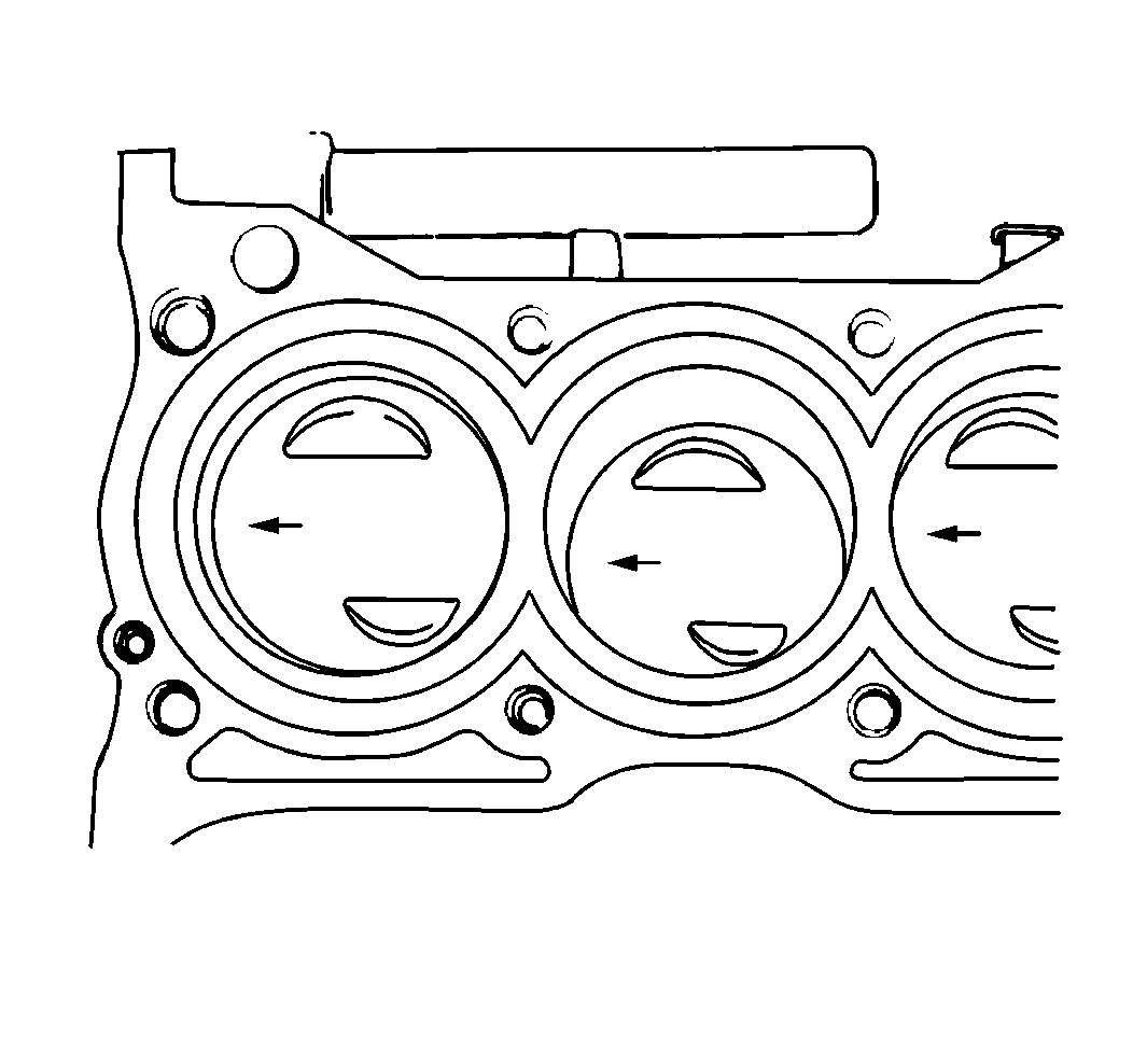
order to install the piston and the connecting rod into the connecting bore.
Ensure that the arrow mark on top of the piston points to the crankshaft
pulley end.
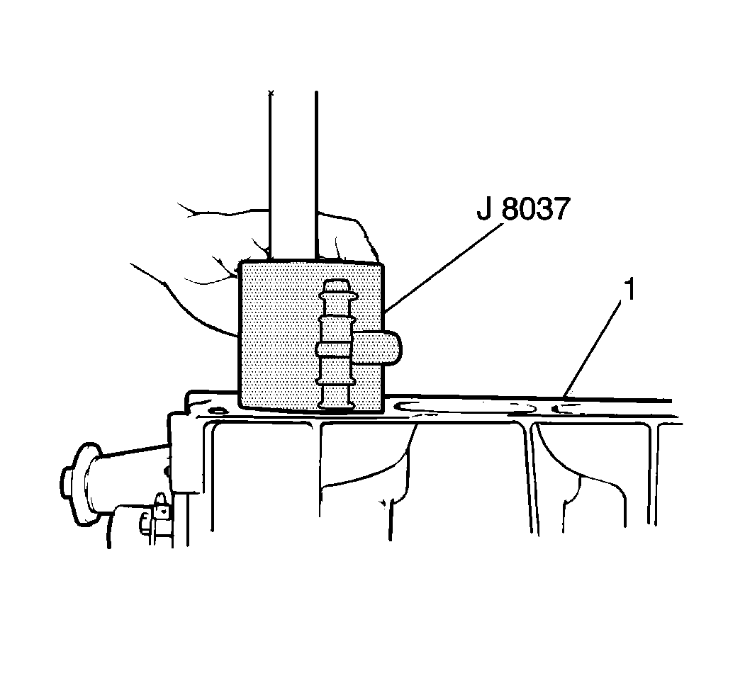
- Use a hammer handle in order to tap the piston
head and install the piston into the cylinder bore. Keep the J 8037
pressed securely against the top of the
cylinder block (1) until all of the piston rings have entered the cylinder
bore.
- Remove the hose pieces from the connecting rod bolts.
Important: Be sure to point the arrow mark on the cap toward the crankshaft pulley
side.
- Install the connecting rod bearing cap to the connecting rod.
- Secure the connecting rod bearing cap with two nuts.
Tighten
Tighten the connecting rod bearing nuts to 35 N·m (26 lb ft).
Important: After the rear main housing bolts are tightened, the gasket may extend
past the rear main seal housing. Trim the excess with a sharp knife so the
gasket is flush with the cylinder block.
- Install the rear main seal housing and new gasket to the engine. Secure
the housing and gasket with five rear main seal housing bolts. There are two
different bolt lengths. Ensure correct placement.
Tighten
Tighten the rear main seal housing bolts to 12 N·m (106 lb in).
- Apply a thin coat of oil to the J 34853
.
- Use the J 34853
in
order to install the oil seal to the crankshaft.
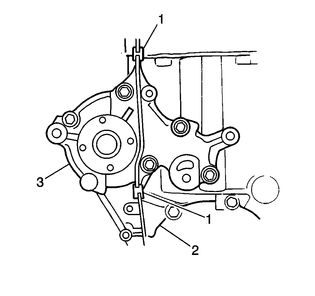
- Use the J 34853
in order to install the two guide pins and the oil pump assembly
with a new gasket and rubber oil pump-to-coolant pump seals (1) to the crankshaft
.

- Secure the two guide pins and the oil pump assembly
with seven bolts.
Tighten
Tighten all of the oil pump bolts to 11 N·m (97 lb in).
- Ensure that the oil seal lip is not upturned. Remove the J 34853
.
- Inspect the edge of the oil pump gasket.
| • | Trim the edge with a sharp knife if it protrudes out into the
engine oil pan mating surface. |
| • | Make the edge smooth and flush with the mating surface of the
engine oil pan. |
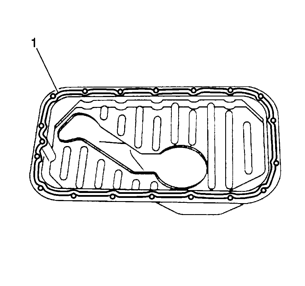
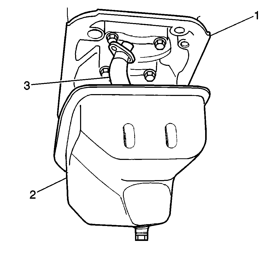
- Apply gasket paste GM P/N 1050026, or the equivalent,
to the engine oil pan mating surface (1) in a continuous bead.
- Install the oil pump strainer to the engine oil pan.
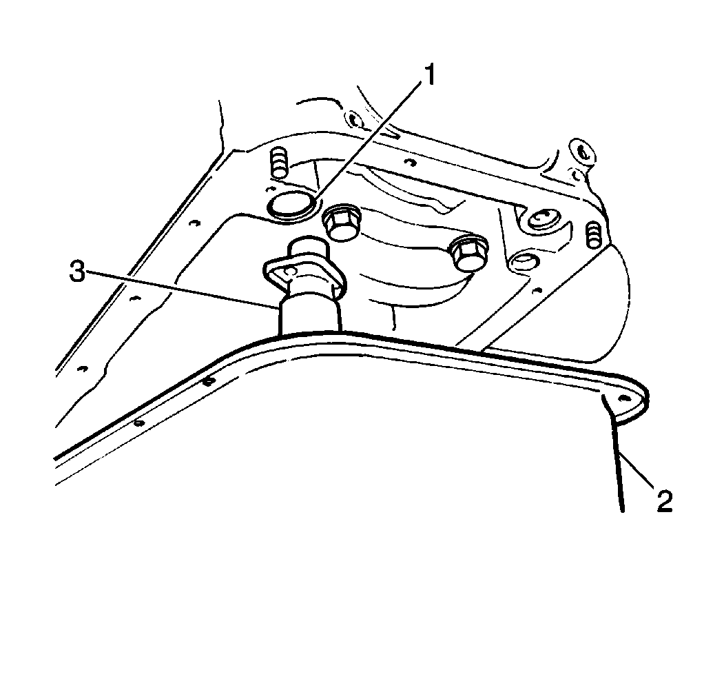
- Install the oil pump strainer (3) to the cylinder
block. Secure the strainer with two bolts.
Tighten
Tighten the oil pump strainer bolts to 11 N·m (97 lb in).
- Install the engine oil pan (2) to the cylinder block. Secure the
engine oil pan with sixteen and two nuts.
Tighten
Tighten the engine oil pan nuts and bolts to 11 N·m (97 lb in).
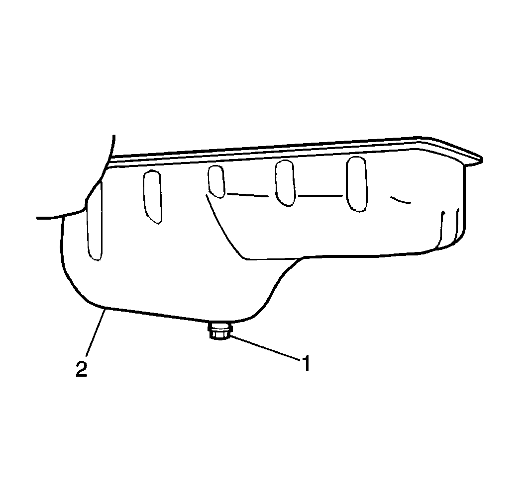
- Install the engine oil pan drain plug and gasket to the engine
oil pan.
Tighten
Tighten the engine oil drain plug to 35 N·m (26 lb ft).
- Install the new O-ring seal to the coolant intake pipe.
- Install the coolant intake pipe to the cylinder block. Secure
the pipe with one bolt.
Tighten
Tighten the coolant intake pipe bolt to 11 N·m (97 lb in).
- Install the coolant pump with the new gasket to the engine. Secure
the coolant pump with five bolts.
Tighten
Tighten the coolant pump bolts to 12 N·m (106 lb in).
- Install the rubber seals between the coolant pump and the oil
pump and between the coolant pump and the cylinder head.
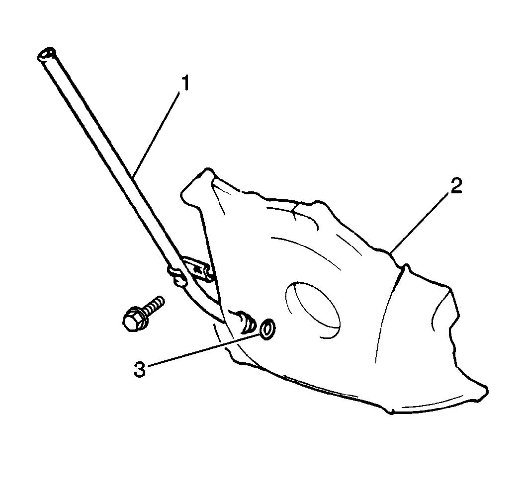
- Install the engine oil level indicator tube with a new O-ring
to the cylinder block. Secure the tube with a mounting bolt. Do not fully
tighten.
Tighten
Tighten the mounting bolt to 11 N·m (97 lb in).
- Install the right-side engine mount to the engine. Secure the
engine mount with three right-side engine mount-to-engine bracket bolts.
Tighten
Tighten the three right-side engine mount-to-engine bracket bolts to
55 N·m (40 lb ft).
- Install the left-side engine mount to the engine. Secure the mount
with three left-side engine mount-to-engine bracket bolts.
Tighten
Tighten the three mount-to-engine bracket bolts to 55 N·m
(40 lb ft).
- Install the cylinder head onto the cylinder block. Refer to
Camshaft Replacement
in this section.
