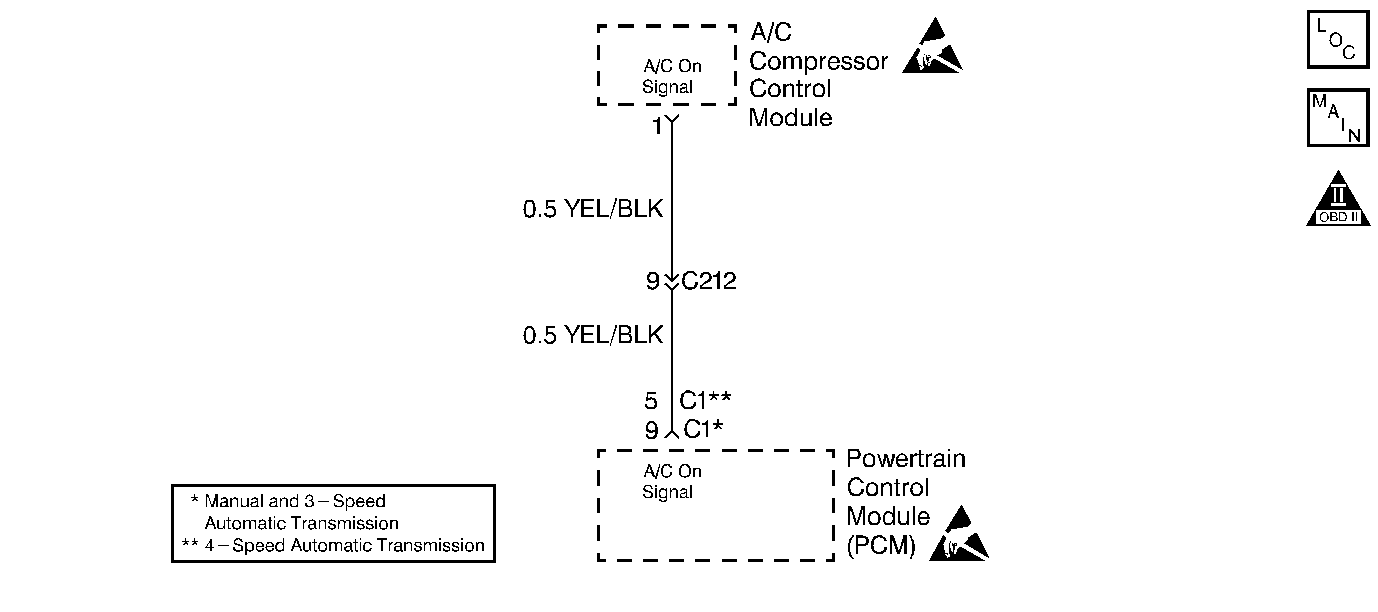
Circuit Description
This signal is sent from the A/C compressor control module. The powertrain control module (PCM) detects whether or not the A/C system is operating via the A/C compressor control module. The extra load the A/C system demands from the engine requires a higher idle speed. When the PCM receives the A/C ON signal, it will activate the Idle Air Control (IAC) valve and the idle speed will increase.
Diagnostic Aids
An intermittent malfunction may be caused by a fault in the A/C sensor circuit. Inspect the wiring harness and components for any of the following conditions:
| • | Backed out terminals. |
| • | Improper mating of terminals. |
| • | Broken electrical connector locks. |
| • | Improperly formed or damaged terminals. |
| • | Faulty terminal to wire connections. |
| • | Physical damage to the wiring harness. |
| • | A broken wire inside the insulation. |
| • | Corrosion of electrical connections, splices, or terminals. |
Use a scan tool in order to monitor the A/C switch parameter. When the A/C switch is in the ON position and the blower speed is in any speed except OFF, the scan tool should read ON. When the A/C switch is OFF, the scan tool should read OFF.
Test Description
The numbers below refer to the step numbers in the Diagnostic Table.
-
This step checks for an open or a short to ground in the YEL/BLK wire, or a faulty PCM.
-
This step checks for a faulty PCM or for a faulty A/C compressor control module.
Step | Action | Value(s) | Yes | No |
|---|---|---|---|---|
1 | Did you perform the Powertrain On-Board Diagnostic (OBD) System Check? | -- | ||
Does the DMM read within the specified value? | B+ | |||
Does the DMM read within the specified value? | 0 volts | System OK | ||
4 |
Was a repair necessary? | -- | ||
5 | Replace the A/C compressor control module. Refer to Air Conditioning. Is the action complete? | -- | -- | |
6 | Replace the PCM. Refer to Powertrain Control Module Replacement Is the action complete? | -- | -- | |
7 | Operate the vehicle within the conditions under which the original symptom was noted. Does the system now operate properly? | -- | System OK | Go To Diagnostic Aids |
