Removal Procedure
Tools Required
| • | J 21867-02 Ball Joint Remover |
| • | J 22888-D Ball Stud Remover |
- Raise the vehicle. Support the vehicle. Refer to Lifting and Jacking the Vehicle in General Information.
- Remove the tire and wheel assembly. Refer to Wheel Removal in Tires and Wheels.
- On four-wheel drive models, remove the locking hub. Refer to Locking Hub Replacement in this section.
- On two-wheel drive models, remove the hub end cap.
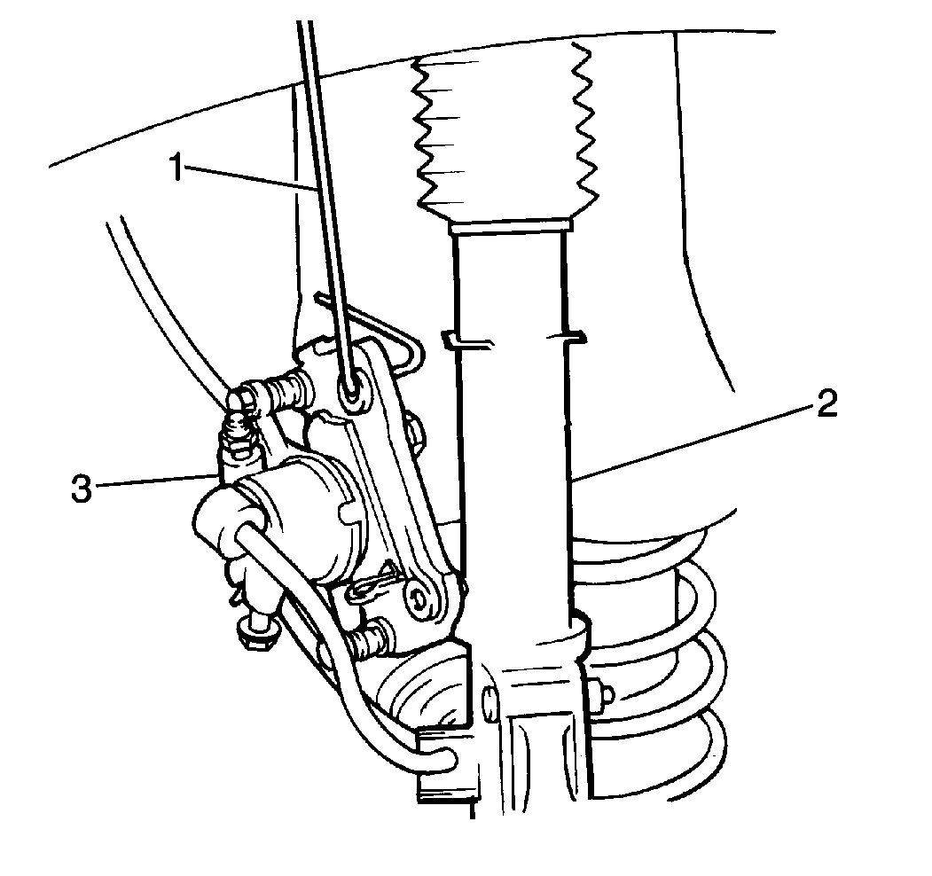
- Remove the two caliper carrier bolts.
- Remove the brake caliper from the steering knuckle.
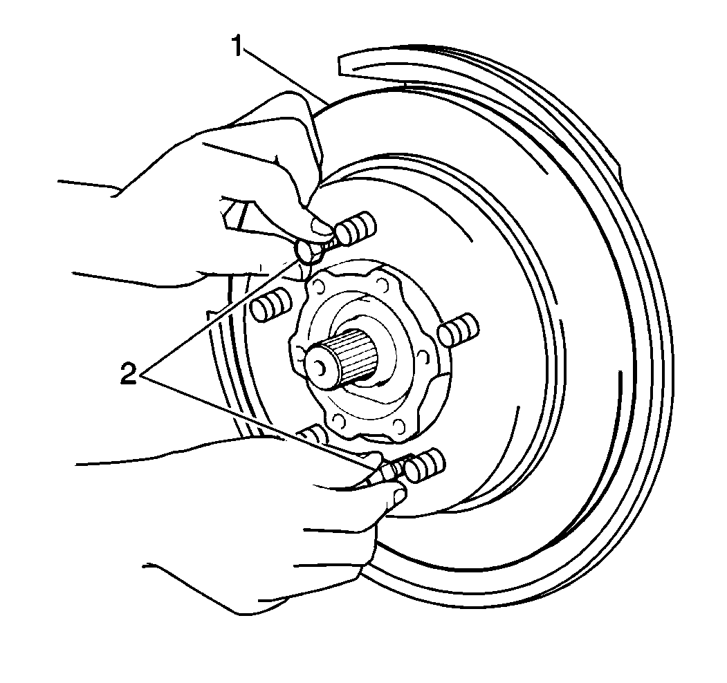
- Remove the brake rotor (1) from the wheel hub.
- On ABS equipped vehicles, remove the electrical connector from the wheel speed sensor.
- On ABS equipped vehicles, remove one bolt and the wheel speed sensor from the spindle.
- Remove the wheel hub and the bearing. Refer to Front Wheel Bearing and Hub Replacement in this section.
- Remove the four bolts holding the dust shield to the steering knuckle.
- Tap the spindle with a hammer in order to remove the spindle from the steering knuckle.
- Support the control arm (1) with a floor jack (2).
- Remove the two strut-to-steering knuckle bolts (1) and nuts (3).
- Remove the following components:
- Use the J 21867-02 in order to remove the tie rod end from the steering knuckle.
- Remove the following components from the ball stud:
- Use the J 22888-D in order to separate the ball stud from the steering knuckle.
- Remove the knuckle from the vehicle.
- Remove the oil seal from the knuckle.

Important: Suspend the caliper assembly with wire (1) in order to prevent damage to the brake hose.

If it is not possible to remove the rotor by hand, use the following steps in order to remove the rotor:
| 7.1. | Install two 8 mm bolts (2) into the rotor. |
| 7.2. | Tighten the bolts in order to force the rotor off of the wheel hub. |
Remove the dust shield from the steering knuckle.


Separate the strut from the knuckle.
| • | The tie rod end cotter pin |
| • | The castle nut |
| • | The cotter pin |
| • | The castle nut |
Installation Procedure
Tools Required
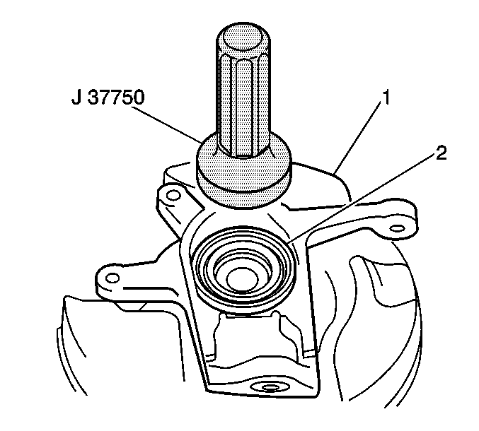
J 37750 Steering Knuckle Oil Sealer Installer
- Use the J 37750 in order to install the new oil seal to the steering knuckle.
- Install the steering knuckle to the ball stud. Secure the steering knuckle with the castle nut. Finger tighten the nut.
- Install the steering knuckle to the strut. Secure the steering knuckle with two nuts (3) and bolts (1).
- Install the tie rod end to the knuckle. Secure the tie rod with a castle nut.
- Remove the floor jack.
- Install the cotter pins to the ball stud and the tie rod end.
- Fill the recess in the wheel spindle with 10 g (0.35 oz) of GM Lubriplate P/N 1052196, or the equivalent.
- Install the spindle to the steering knuckle.
- Install the dust shield to the steering knuckle. Secure the dust shield with four bolts.
- Install the wheel hub and bearing. Refer to Front Wheel Bearing and Hub Replacement in this section.
- On ABS equipped vehicles, connect the wheel speed sensor to the spindle. Secure the sensor with one bolt.
- On ABS equipped vehicles, install the electrical connector to the wheel speed sensor.
- Install the brake rotor to the wheel hub.
- Install the brake caliper to the rotor and the steering knuckle. Secure the brake caliper with two caliper carrier bolts.
- On two-wheel drive models, install the hub end cap.
- On four-wheel drive models, install the locking hub. Refer to Locking Hub Replacement in this section.
- Install the tire and wheel assembly. Refer to Wheel Installation in Tires and Wheels.
- Lower the vehicle.


Notice: Use the correct fastener in the correct location. Replacement fasteners must be the correct part number for that application. Fasteners requiring replacement or fasteners requiring the use of thread locking compound or sealant are identified in the service procedure. Do not use paints, lubricants, or corrosion inhibitors on fasteners or fastener joint surfaces unless specified. These coatings affect fastener torque and joint clamping force and may damage the fastener. Use the correct tightening sequence and specifications when installing fasteners in order to avoid damage to parts and systems.
Tighten
| • | Tighten the ball stud castle nut to 58 N·m (43 lb ft). |
| • | Tighten the strut-to-knuckle nuts and bolts to 90 N·m (66 lb ft). |
Tighten
Tighten the tie rod end castle nut to 40 N·m (30 lb ft).
Tighten
Tighten the dust shield bolts to 15 N·m (11 lb ft).
Tighten
Tighten the wheel speed sensor retaining bolt to 10 N·m
(89 lb in).
Tighten
Tighten the brake caliper carrier bolts to 88 N·m (65 lb ft).
