Removal Procedure
- Disconnect the negative battery cable.
- Loosen the upper and lower A/C compressor mounting bolts (if equipped).
- Loosen the upper and lower power steering pump mount bolts.
- Remove the A/C compressor (if equipped) and/or power steering drive belt from the pulleys.
- Loosen the upper and lower generator mounting bolts.
- Remove the generator/coolant pump drive belt from the pulleys.
- Remove the following from the coolant pump:
- Raise and support the vehicle. Refer to Lifting and Jacking the Vehicle in General Information.
- Remove the four bolts and the front skid plate from the vehicle (if equipped).
- Remove the two lower radiator shroud bolts.
- Lower the vehicle.
- Remove the two bolts from the A/C suction line brackets at the right side of the radiator core support (if equipped). Carefully reposition the suction line for the radiator shroud removal access.
- Remove the upper radiator shroud bolts and the radiator shroud from the radiator.
- Remove five bolts and the crankshaft pulley (4) from the crankshaft.
- Disconnect the oil pressure sending unit wire conduit from the timing belt cover (2).
- Remove the following from the engine:
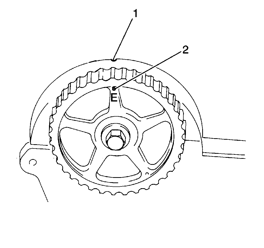
- Align the timing marks on the cylinder head cover (1) and the camshaft timing belt gear (2).
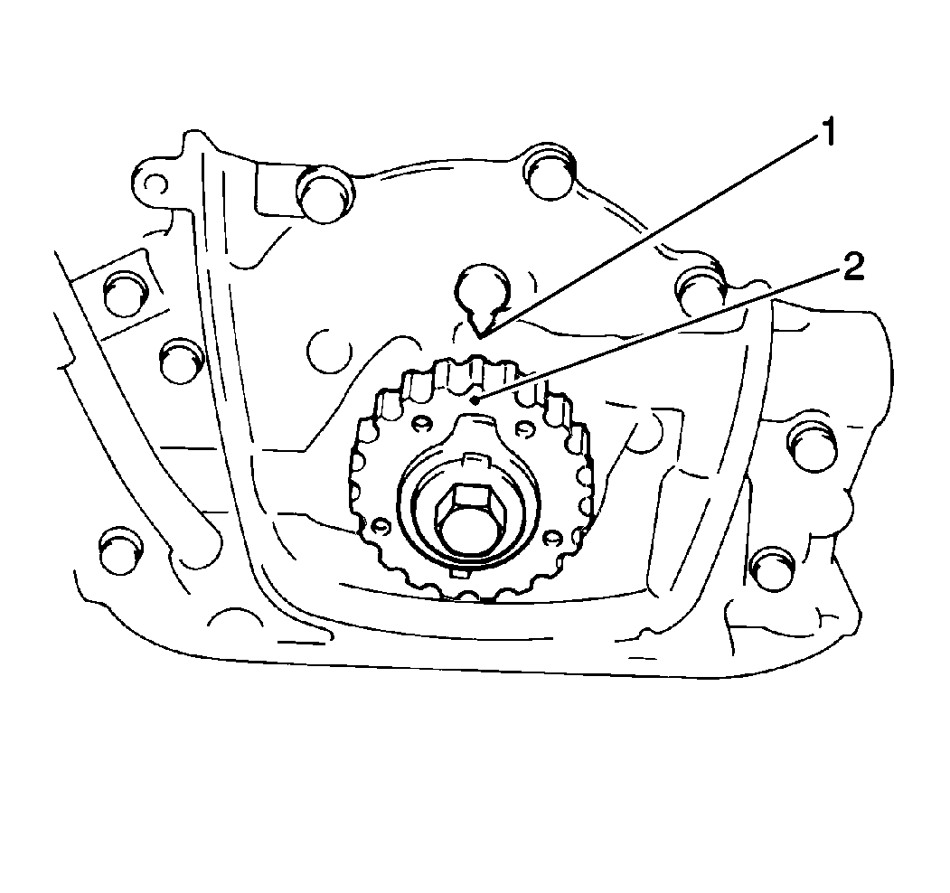
- Ensure the alignment of the timing marks on the oil pump casting (2) and the crankshaft timing belt gear (1).
- Loosen the timing belt tensioner bolt (4).
- Remove the timing belt tensioner spring from the timing belt tensioner plate (1).
- Remove the timing belt from the camshaft and the crankshaft timing belt gears.
- Remove the following from the engine:
Caution: Unless directed otherwise, the ignition and start switch must be in the OFF or LOCK position, and all electrical loads must be OFF before servicing any electrical component. Disconnect the negative battery cable to prevent an electrical spark should a tool or equipment come in contact with an exposed electrical terminal. Failure to follow these precautions may result in personal injury and/or damage to the vehicle or its components.
| • | Four nuts |
| • | The cooling fan |
| • | The coolant pump pulley |
Important: If the radiator shroud is difficult to remove, drain the cooling system and disconnect the upper radiator hose from the radiator to gain access.
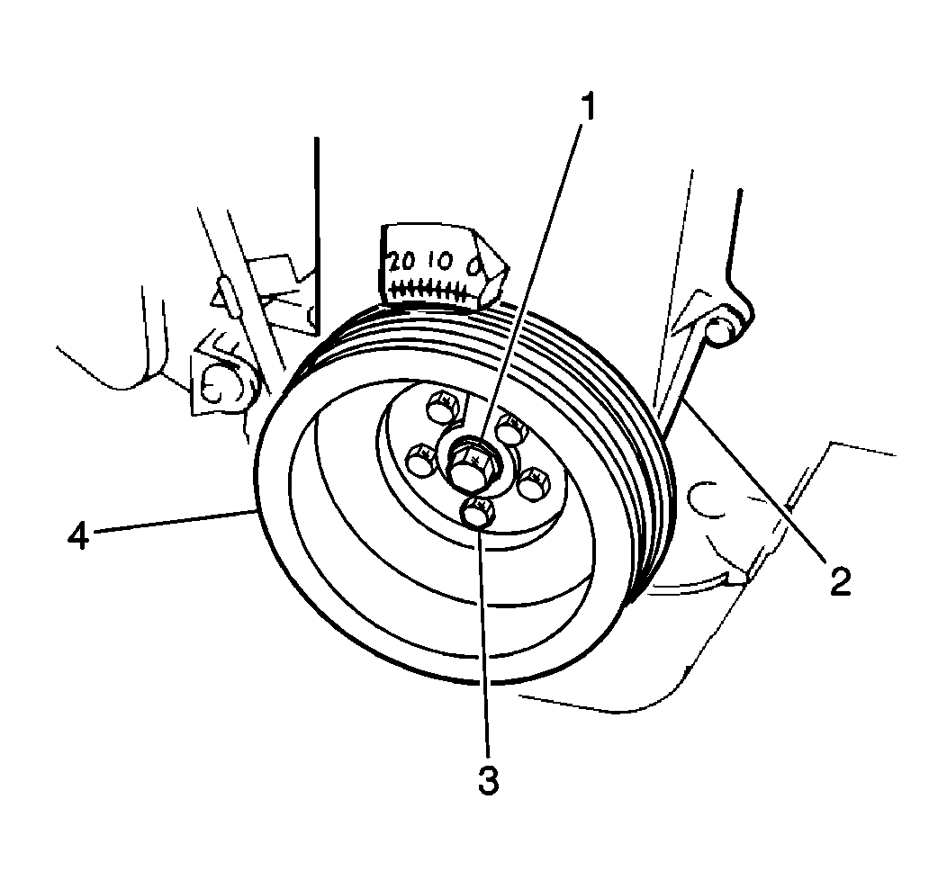
Important: It is not necessary to remove the crankshaft pulley center bolt when removing the crankshaft pulley.
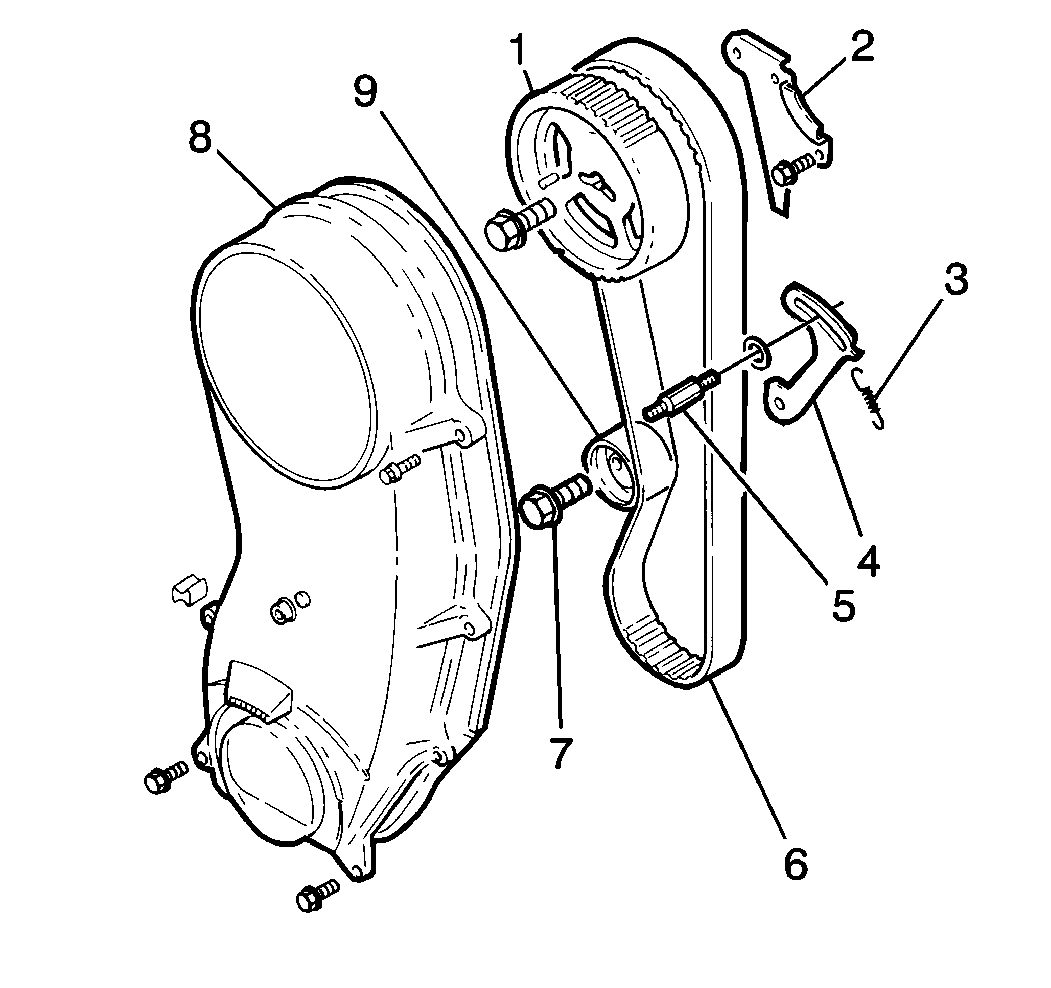
| • | Eight bolts |
| • | One nut |
| • | The timing belt cover (8) |
Important: There are two sets of timing marks which must be aligned to ensure the correct engine timing belt installation. A notch in the camshaft timing belt gear designed as E must be aligned with the notch in the cylinder head cover. A punch mark on the crankshaft timing belt gear should then align with the arrow in the oil pump casting. Ensure alignment of both sets of marks prior to the timing belt removal to ensure correct timing belt installation and engine timing.
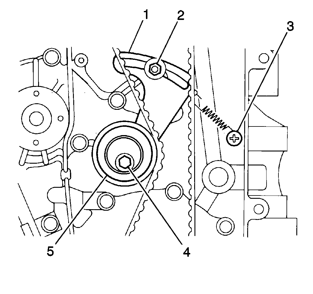
| • | One stud (2) |
| • | One bolt (4) |
| • | The timing belt tensioner (5) |
| • | The tensioner plate (1) |
- Inspect the timing belt (6) for wear or cracking. Replace the belt if necessary.
- Inspect the tensioner (9) for smooth operation. Replace the tensioner if necessary.

Notice: Do not turn the crankshaft and camshaft independently of one another once the timing belt has been removed. If the crankshaft or camshaft is turned independently, interference between the pistons and valves may occur causing component damage.
Installation Procedure
Notice: When installing a new or used timing belt, the directional arrows on the timing belt must be matched with the rotation of the crankshaft. If this precaution is not observed, excessive wear and timing belt failure may occur.
Important: Do not tighten the timing belt tensioner stud and bolt to specification until the timing belt is properly installed. Install the timing belt tensioner and stud and bolt finger tight only.
- Install the timing belt tensioner plate and tensioner to the engine. Secure the tensioner plate with the timing belt tensioner stud and bolt.
- Push the timing belt tensioner plate up for the timing belt installation.
- Install the timing belt onto the camshaft and the crankshaft timing belt gears (1).
- Inspect the timing marks on the cylinder head cover and the camshaft timing belt gear (1) for the alignment as well as the timing marks on the oil pump casting and the crankshaft timing belt gear. If these two sets of timing marks are not properly aligned, remove the timing belt and align both sets of marks as previously outlined in this procedure.
- Install the timing belt tensioner spring to the timing belt tensioner plate (1).
- Install the timing belt cover to the engine. Secure the cover with one nut and eight bolts.
- Connect the oil pressure sending unit wire conduit to the timing belt cover.
- Install the crankshaft pulley (4) to the crankshaft. Secure the pulley with five bolts (3).
- Install the radiator shroud to the radiator. Secure the shroud with two bolts.
- Carefully reposition the A/C suction line and brackets to the right side of the radiator core support (if equipped). Secure the line and brackets with two bolts.
- Raise and support the vehicle. Refer to Lifting and Jacking the Vehicle in General Information.
- Install the two lower radiator shroud bolts.
- Install the front skid plate to the vehicle (if equipped). Secure the skid plate with four bolts.
- Lower the vehicle.
- Install the coolant pump pulley and cooling fan to the coolant pump. Secure the pulley and fan with four nuts.
- Install the generator/coolant pump drive belt to pulleys.
- Install the A/C compressor (if equipped) and/or power steering drive belt to pulleys.
- Connect the negative battery cable. Refer to Battery Replacement in Engine Electrical.


Notice: Use the correct fastener in the correct location. Replacement fasteners must be the correct part number for that application. Fasteners requiring replacement or fasteners requiring the use of thread locking compound or sealant are identified in the service procedure. Do not use paints, lubricants, or corrosion inhibitors on fasteners or fastener joint surfaces unless specified. These coatings affect fastener torque and joint clamping force and may damage the fastener. Use the correct tightening sequence and specifications when installing fasteners in order to avoid damage to parts and systems.
Important: Rotate the crankshaft two complete revolutions to remove any slack from the timing belt and to properly seat the timing belt. When all of the slack has been removed from the timing belt, inspect both sets of the timing marks to ensure that they are aligned respectively.
Tighten
| • | Tighten the timing belt tensioner stud to 11 N·m (97 lb in). |
| • | Tighten the timing belt tensioner bolt to 27 N·m (20 lb ft). |
Tighten
Tighten the timing belt cover nut and bolts to 10 N·m (89 lb in).

Tighten
Crankshaft pulley bolts to 16 N·m (12 lb ft).
Tighten
Tighten the upper shroud bolts to 11 N·m (97 lb in).
Tighten
Tighten the A/C suction line bracket bolts to 10 N·m (89 lb in).
Tighten
Tighten the lower shroud bolts to 11 N·m (97 lb in).
Tighten
Tighten the Front skid plate bolts to 55 N·m (40 lb ft).
Tighten
Tighten the coolant fan nuts to 11 N·m (97 lb in).
| • | Adjust the generator/coolant pump drive belt. Refer to Cooling and Radiator. |
| • | Adjust the A/C compressor (if equipped) and/or the power steering drive belt. Refer to HVAC and/or Power Steering Gear and Pump. |
