- Rear wheel antilock (ABS)
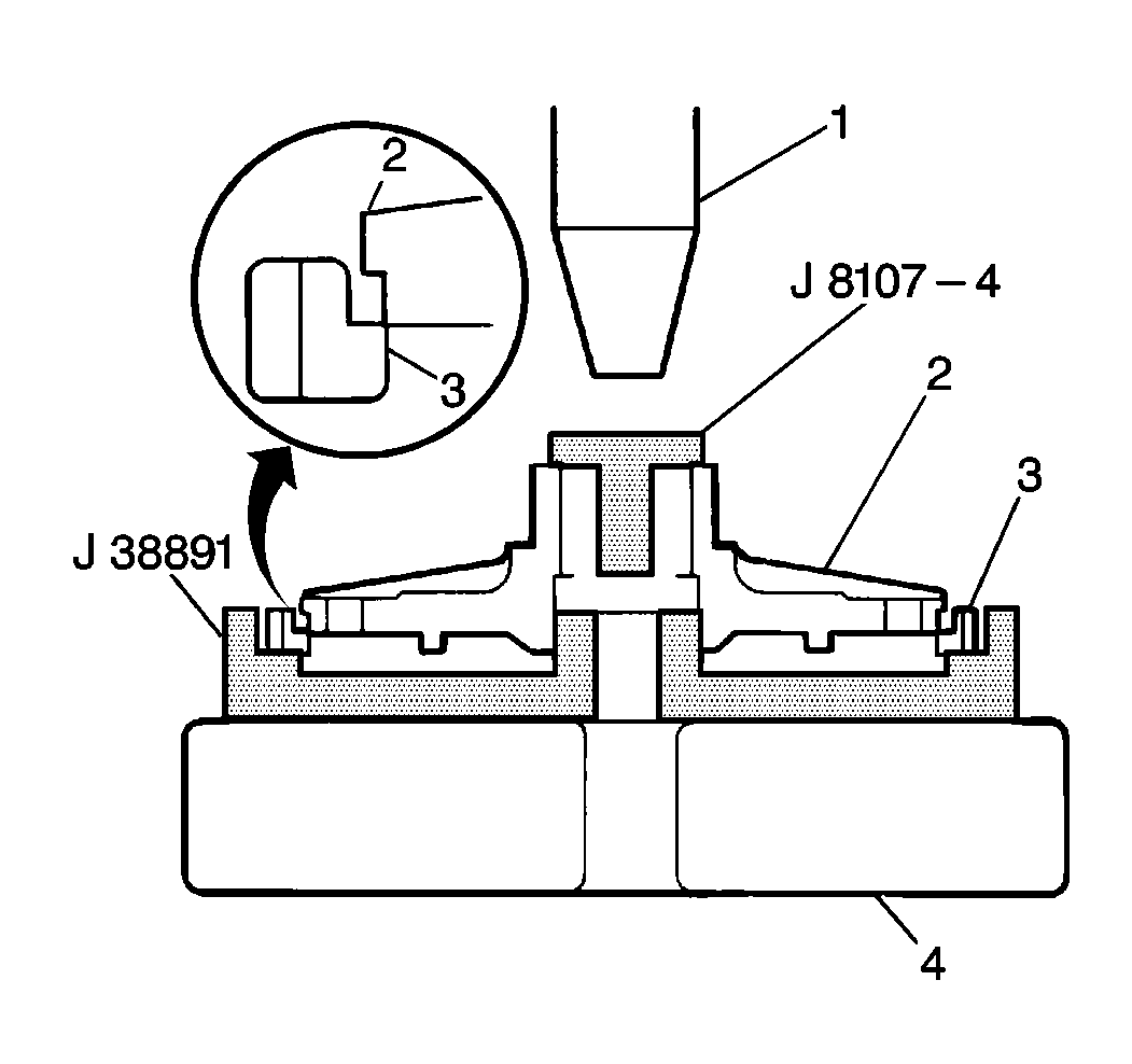
speed sensor exciter ring (3) onto the left differential case (2) half using
the J 38891
exciter ring
installer and the J 8107-4
.
Important: Observe the hydraulic pressure gauge during speed sensor exciter ring
installation. Pressure exerted on the exciter ring should not exceed 500 kg
(1102 lbs). If pressure higher than specified is needed to install
the left differential case into the exciter ring, the two components may
be misaligned. Reposition the left differential case in the exciter ring
so that the pressure will be even around the perimeter and repeat the installation
procedure.
- Place the exciter ring inside the J 38891
on a hydraulic press.
- Center the left differential case half in the exciter ring with
the J 8107-4
side in the
left axle shaft bore.
- Press the differential case half slowly and evenly into the exciter
ring.

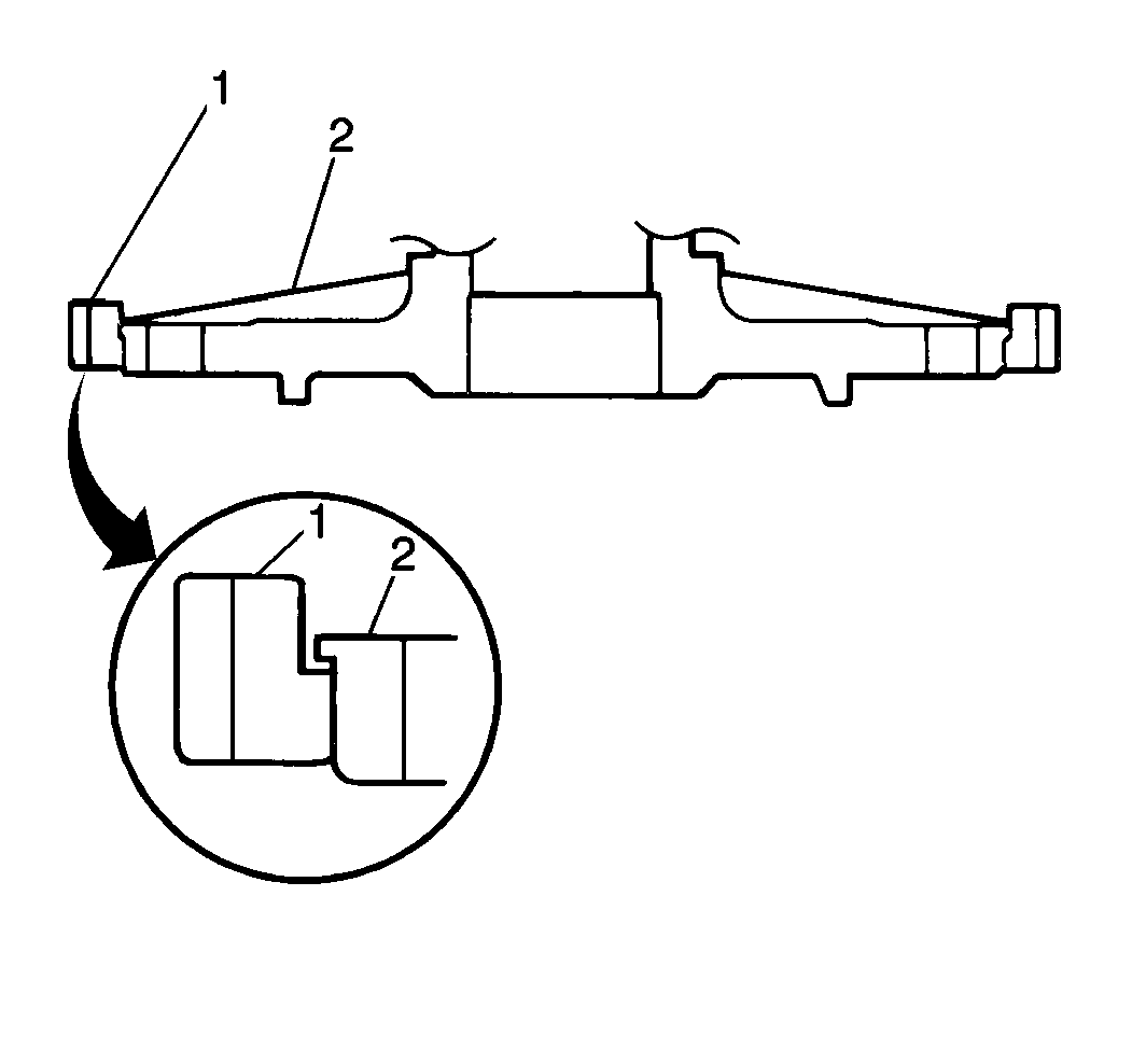
- Inspect the left differential
case (2) face to make sure the speed sensor exciter ring (1) is flush with
or higher than the left differential case.
Notice: Use the correct fastener in the correct location. Replacement fasteners
must be the correct part number for that application. Fasteners requiring
replacement or fasteners requiring the use of thread locking compound or sealant
are identified in the service procedure. Do not use paints, lubricants, or
corrosion inhibitors on fasteners or fastener joint surfaces unless specified.
These coatings affect fastener torque and joint clamping force and may damage
the fastener. Use the correct tightening sequence and specifications when
installing fasteners in order to avoid damage to parts and systems.
- Install the rear
wheel speed sensor, if the vehicle is equipped. Secure with the rear wheel
speed sensor bolt.
Tighten
Tighten the rear wheel speed sensor bolt to 23 N·m (17 lb ft).

- Install the following
in the right differential case:
| • | Right side gear and washers |
| • | Differential pinion gears (2) and washers (1) |
| • | Pinion cross shaft joint |

- Measure the right differential
side gear (1) end play using the J 8001
.
- Insert fingers through the bottom openings of the right differential
case (2) half and move the right differential side gear (1) up and down while
observing the J 8001
.
The right differential side gear end play should measure 0.12 to 0.37 mm
(0.005 to 0.014 in).
- Replace the selective shim with the appropriate size to obtain
correct end play, if the right differential side gear end play is too high
or low.

- Install the cross shaft
roll pins into the right differential case (4) half. The roll pin
ends should be flush with the right differential case surface.

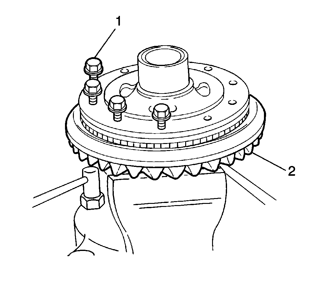
- Install the left differential
side gear (1) and washers (2) into the right differential case.

- Install the left differential
case half and ring gear (2) to the right differential case half. Secure
with ten bolts (1)
Tighten
Tighten the ring gear bolts to 90 N·m (65 lb ft).

- Measure the left differential
side gear end play using the J 8001
the J 35138
.
- Insert the J 35138
in through the left axle shaft differential case (1) bore.
- Adjust the J 35138
until the J 35138
has
a firm grasp on the left differential side gear.
- Move the J 35138
up
and down while observing the J 8001
. The left differential side gear end play should measure 0.12
to 0.37 mm (0.005 to 0.014 in).
- Replace the selective shim with the appropriate size to obtain
the correct end play if the left differential side end play is too high or
low.

- Install the side gear
preload to the left differential case (1) using the J 38890
.
- Insert the J 38890
into either side bearing with a torque wrench.
- Measure the side bearing preload.
The maximum side gear preload 2.4 N·m (21 lb in).
- Inspect the side and differential pinion gears for foreign material
or damage if the preload exceeds the specification.
Important: After the correct end play and preload has been obtained, remove the
ring gear bolts and apply GM P/N 12345493, or the equivalent, to the threaded
portion of each ring gear bolt and install into the differential case
assembly.
Tighten
Tighten the ring gear bolts to 90 N·m (65 lb ft).

- Install the right differential
side bearing (1)
on the right side of the differential case assembly (2) using the J 37758
with the J 8092
.
- Place the differential case assembly on a hydraulic press using
the J 8107-4
for support.
- Place the right side bearing on the right differential case with
the taper side up using the J 37759
with the J 8092
.
- Slowly press the right differential side bearing onto the right
differential case.

- Install the left differential
case (2) to the
left side of the differential case assembly using the J 37758
with the J 8092
and the J 8107-4
.
- Place the differential case assembly on a hydraulic press with
the J 8107-4
for support
and to protect the right differential side bearing (1).
- Place the left differential side bearing on the left differential
case with the taper side up using the J 37758
with the J 8092
.
- Slowly press the left differential side bearing onto the left
differential case.

- Install the inner pinion
bearing race using the J 37759
and the J 8092
.
- Place the differential carrier (1) on a hydraulic press.
- Position the inner pinion bearing race over its bore.
- Use the J 37759
inner
with the J 8092
to slowly
press the inner pinion bearing race evenly into the differential carrier.

- Install the outer pinion
bearing race (1) using
the J 37758
with the J 8092
.
- Place the differential carrier (2) on a hydraulic press.
- Position the outer pinion bearing race over its bore.
- Press the outer pinion bearing race slowly and evenly into the
differential carrier using the J 37758
with the J 8092
.


