Brake System Testing Diagnostic
Test the brakes on a dry, clean, reasonably smooth and level roadway. A true braking test cannot be made if the roadway is wet, greasy, or covered with loose dirt because all the tires will not grip the road equally. Testing is also adversely affected when the roadway is crowned, throwing the weight of the vehicle toward the wheels on one side; or when the roadway is rough, making the wheels bounce.
Test the brakes at different vehicle speeds, with both light and heavy pedal pressure. Locked brakes and sliding tires do not indicate brake efficiency, since heavily braked but turning wheels will stop a vehicle in less distance than will locked wheels.
Because of a higher deceleration capability, a firmer pedal may be felt at higher deceleration rates.
Brake System Testing LPSV Test
Weight Load Test
Tools Required
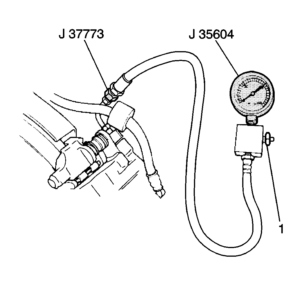
| • | J 35604 Pressure Gage |
| • | J 37773 Pressure Gage Adapter |
Important: The following conditions must be met before proceeding:
• The fuel tank is full. • The vehicle is loaded with a spare tire, tools, a jack and a jack
handle. • The vehicle is free from any other load. • The vehicle is on a level floor.
- Place 100 kg (221 lbs) of weight slowly in the cargo area, right above the rear axle.
- Install the J 35604 with the J 37773 to the left front caliper bleeder valve.
- Install the J 35604 with the J 37773 to the rear wheel cylinder bleeder valve.
- While pressing the brake pedal gradually until the front brake hydraulic pressure reaches 50 kg/cm² (711 psi), observe the rear brake hydraulic pressure. Refer to Component Specifications .
- Increase the front brake hydraulic pressure to 100 kg/cm² (1422 psi) and observe rear brake hydraulic pressure. Compare the reading with Component Specifications .
- If the rear brake pressure is higher than specifications, loosen the bolt securing the lower portion of the load sensing spring and move the bolt upward. A bolt movement of 1 mm will result in an increase of about 2.4 kg/cm² (34.20 psi) in hydraulic pressure. Tighten the load sensing spring bolt after reaching specifications.
- If the rear brake pressure is lower than specifications, loosen the bolt securing the lower portion of the load sensing spring and move the bolt downward. A bolt movement of 1 mm will result in an increase of about 2.4 kg/cm² (34.20 psi) in hydraulic pressure. Tighten load sensing spring bolt after reaching specifications.
- Remove J 35604 and J 37773 .

Tighten
Tighten the load sensing spring bolt to 23 N·m (17 lb ft).
Important: Bleed the brakes. Refer to Hydraulic Brake System Bleeding .
Fail-Safe test
Tools Required
| • | J 35604 Pressure Gage |
| • | J 37773 Pressure Gage Adapter |
- Remove the right front brake pipe from the master cylinder.
- Install J 35604 with the J 37773 to the master cylinder right front brake pipe port.
- Install J 35604 with the J 37773 to the rear wheel cylinder bleeder valve.
- While pressing the brake pedal gradually until the front brake hydraulic pressure reaches 100 kg/cm² (1422 psi), observe the rear brake hydraulic pressure. The rear brake pressure should read 90 to 100 kg/cm² (1350 to 1422 psi). If rear brake pressure is lower than specified, replace the LPSV.
- Remove J 35604 with the J 37773 .
- Install the right front brake pipe to the master cylinder.
- Bleed the brakes. Refer to Hydraulic Brake System Bleeding .
