Wheel Speed Sensor Replacement Front
Removal Procedure
- Raise and support the vehicle on a suitable hoist. Refer to Vehicle Lifting And Jacking in General Information.
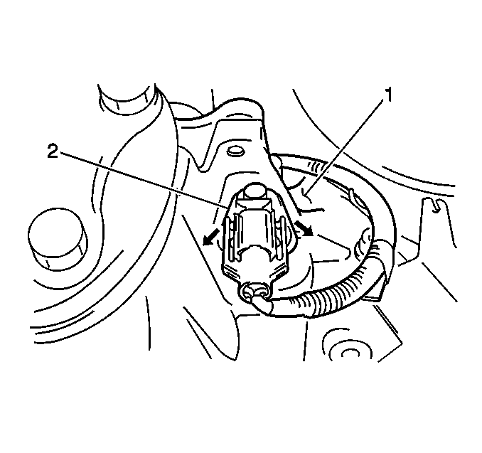
- Disconnect the front wheel speed sensor electrical connector.
- Remove the retaining bolt (3).
- Remove the brake rotor and remove broken pin using a blunt punch.
- Clean the hole using sand paper wrapped around a screwdriver or other suitable tool. Never attempt to enlarge the hole.
- Remove the front wheel speed sensor (1) from the steering knuckle (2).

Important: If the sensor locating pin breaks off and remains in the knuckle during
removal, proceed as follows:
Installation Procedure
- Install the front wheel speed sensor (1) to the steering knuckle (2).
- Install the retaining bolt (3).
- Connect the front wheel speed sensor electrical connector.
- Lower the vehicle.
- Perform the Diagnostic System Check .

Tighten
Tighten the retaining bolt to 8 - 12 N·m
(70.8 - 106.2 lb in).
Wheel Speed Sensor Replacement Rear
Removal Procedure
- Raise and support the vehicle. Refer to Vehicle Lifting and Jacking in General Information.
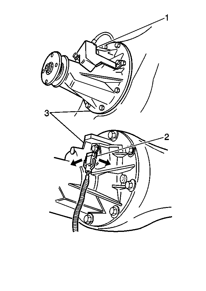
- Remove the two bolts and the rear wheel speed sensor cover (1) from the differential carrier (3).
- Disconnect the rear wheel speed sensor electrical connector (2).
- Remove the retaining bolt and the rear wheel speed sensor from the vehicle.
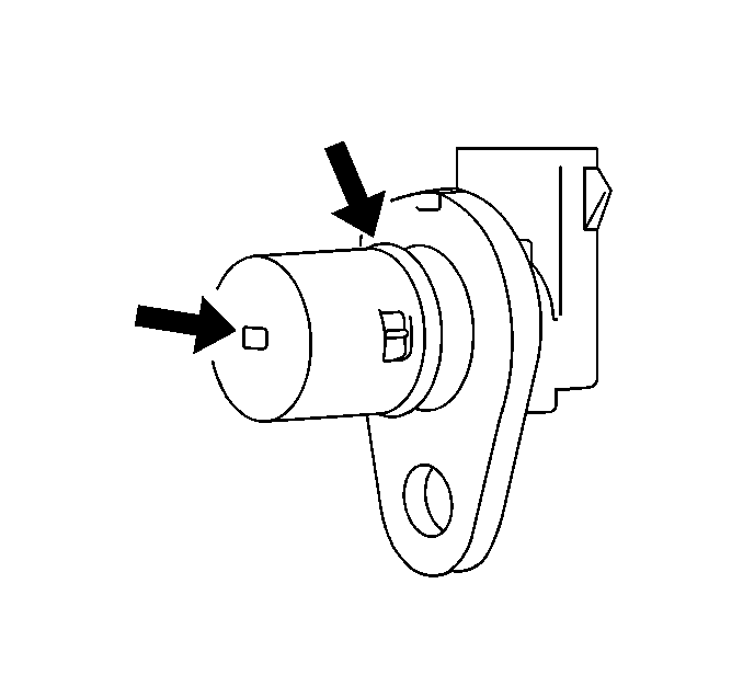
- Inspect for the following on the sensor face:
- Inspect the sensor face for evidence of damage. Inspect the sensor for contact with the toothed sensor ring. The sensor should not contact the toothed sensor ring. Determine and correct the cause of the damage when damage is evident. Replace the sensor if damage interferes with proper operation. Check the axle bearing for excessive wear.


| • | Inspect for an accumulation of metallic particles, dirt, grease, or other contaminants. |
| • | Clean the sensor as required. |
Installation Procedure
Notice: The wheel speed sensor is a tight fit and is to be pushed in by hand. DO NOT force the sensor into position, as damage to the sensor could result.
Notice: Wheel speed sensors must be given an anti corrosion coating before installation to prevent corrosion. Use silicone grease P/N 12345579 or equivalent.
- Install the rear wheel speed sensor into the differential housing (3).
- Install the rear wheel speed sensor retaining bolt.
- Connect the rear wheel speed sensor electrical connector (2).
- Install the rear wheel speed sensor cover (1) and retaining bolts to the differential carrier (3).
- Lower the vehicle.
- Perform the Diagnostic System Check .

Notice: Use the correct fastener in the correct location. Replacement fasteners must be the correct part number for that application. Fasteners requiring replacement or fasteners requiring the use of thread locking compound or sealant are identified in the service procedure. Do not use paints, lubricants, or corrosion inhibitors on fasteners or fastener joint surfaces unless specified. These coatings affect fastener torque and joint clamping force and may damage the fastener. Use the correct tightening sequence and specifications when installing fasteners in order to avoid damage to parts and systems.
Tighten
Tighten the bolt to 23 N·m (17 lb ft).

Tighten
Tighten the cover bolts to 15 N·m (11 lb ft).
