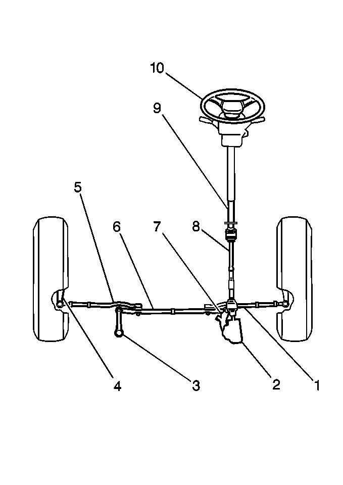
| Figure 1: |
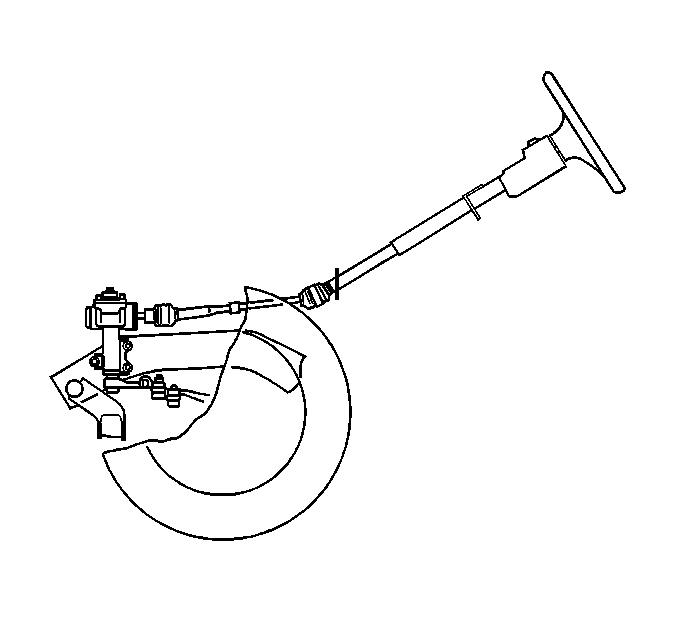
Manual Steering Gear and Linkage

|
| Figure 2: |

|
The rotary motion of the
steering wheel transfers through the following components:
| • | The steering upper shaft |
The pitman arm attaches to the center link. As the pitman arm rotates,
the center link moves linearly, actuating the right tie rod and the left tie
rod. The right tie rod and the left tie rod turn the wheels right or left
through the steering knuckles. The steering system is designed for the
following purposes:
| • | Excellent steering reaction |
| • | Reliable self-restoring action |


