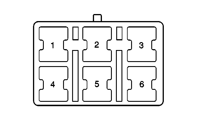
For 1990-2009 cars only
| Table 1: | Data Link Connector (DLC) OBD2 |
| Table 2: | Duty Check Data Link Connector |

| ||||||
|---|---|---|---|---|---|---|
Connector Part Information |
| |||||
Pin | Wire Color | Function | ||||
1-3 | -- | Not Used | ||||
4 | BLK | Ground | ||||
5 | BLK/BLU | Ground | ||||
6 | -- | Not Used | ||||
7 | PPL/WHT | Serial Data | ||||
8 | -- | Not Used | ||||
9 | PPL | Serial Data | ||||
10-15 | -- | Not Used | ||||
16 | WHT | Battery Positive Voltage | ||||

| ||||||
|---|---|---|---|---|---|---|
Connector Part Information |
| |||||
Pin | Wire Color | Function | ||||
1 | -- | Not Used | ||||
2 | BLU/YEL | Diagnostic Request | ||||
3 | -- | Not Used | ||||
4 | BLK/BLU | Ground | ||||
5 | PPL/GRN | Diagnostic Request | ||||
6 | PPL/RED | Upshift Indicator Control | ||||
