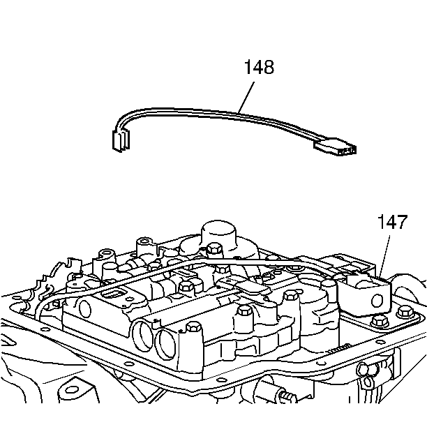
- Remove the manual detent roller and spring assembly bolt (155).
- Remove the manual detent roller and spring assembly (145).
- Disconnect the electrical connections at:
- Remove the TCC solenoid bolt (152).
- Remove the TCC solenoid (147) from the transfer plate reinforcement (146).
- Remove the TCC solenoid (147) from the TCC solenoid pipes (149-150).
- Remove the TCC solenoid pipes (149-150) from the control valve assembly (128) and the transmission case (101).
- Inspect the solenoid pipes for proper fit and that o-ring seals (151) are on the pipes.
- Remove the governor oil pressure switch (137) using a 1-1/16 inch pressure switch socket.
- Remove the oil pressure switch (176) if equipped.
- Remove the transfer plate reinforcement bolt (152).
- Remove the transfer plate reinforcement (146).
- Remove the servo piston cover bolts (152).
- Remove the servo piston cover (169) and gasket (168).
- Remove the control valve assembly bolts (155).
- Remove the control valve assembly (128).
- Remove the manual valve link (139).
- Remove the spacer plate (130) and gaskets (129) and (132).
- Remove the checkball (193) from the transmission case passage.


| • | the governor oil pressure switch (137) |
| • | the torque converter clutch (TCC) solenoid (147) |
| • | the transmission case electrical connector (148) |


Important: Note the position of the manual valve link, (the long end into the manual valve, the short end into the detent lever).

- Disconnect the negative battery cable.
- Raise and suitably support the vehicle. Refer to Lifting and Jacking the Vehicle in General Information.
- Remove the transmission fluid pan and gasket from the transmission. Refer to Transmission Fluid Pan Removal in this section.
- Remove the 3 valve body bolts.
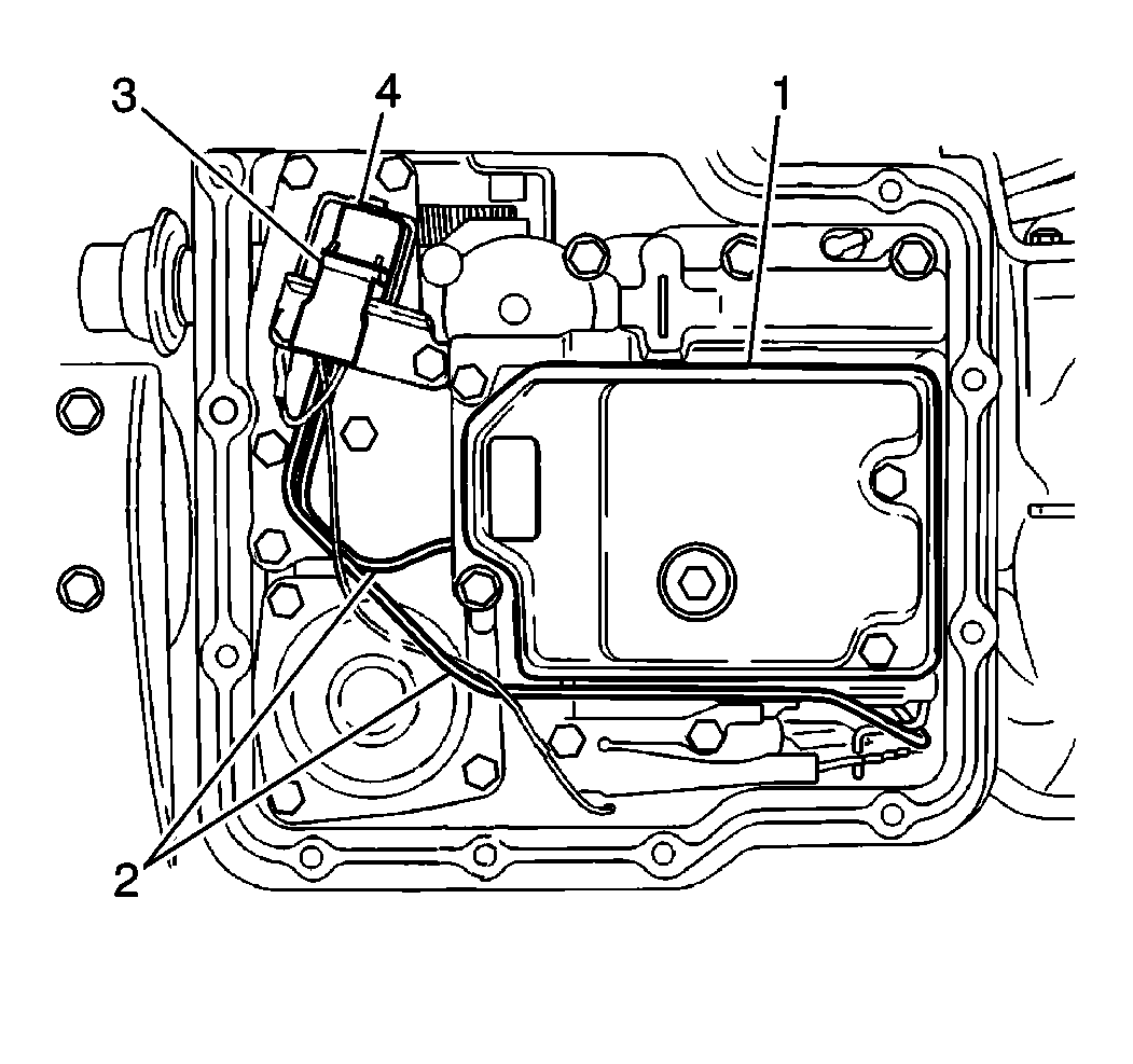
- Remove the fluid filter screen (1) and gasket.
- Remove the torque converter clutch (TCC) solenoid pipes (2) from the following components:
- Disconnect the electrical connector (3) from the TCC solenoid (4).
- Disconnect the electrical connectors (3) from the fluid pressure switch.
- Remove the 2 TCC solenoid bolts.
- Remove the TCC solenoid (4) from the reinforcement plate.
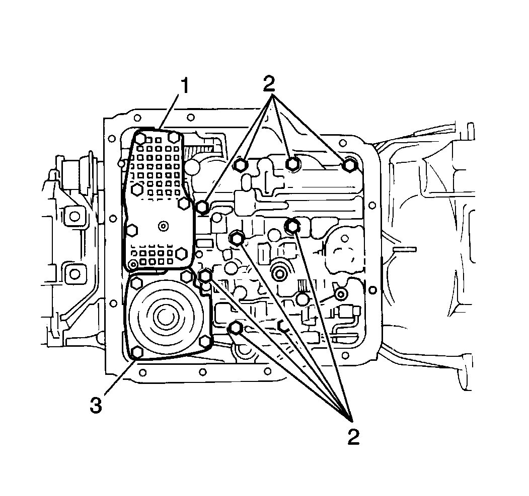
- Remove the 6 reinforcement plate bolts.
- Remove the reinforcement plate (1) from the transmission case.
- Remove the 4 piston servo cover bolts.
- Remove the piston servo cover (3) and the piston servo cover gasket.
- Remove the following components from the transmission case:
Caution: Unless directed otherwise, the ignition and start switch must be in the OFF or LOCK position, and all electrical loads must be OFF before servicing any electrical component. Disconnect the negative battery cable to prevent an electrical spark should a tool or equipment come in contact with an exposed electrical terminal. Failure to follow these precautions may result in personal injury and/or damage to the vehicle or its components.

| • | The TCC solenoid (4) |
| • | The transmission fluid pump |
| • | The valve body |

Notice: When lowering the control valve body assembly, disconnect the manual valve link from the parking lock and range selector lever. Use caution to avoid losing the check ball in the transmission case passage. When the valve body is removed, the check ball should drop out of the case passage onto the top of the valve body.
| • | The 9 valve body bolts (2) |
| • | The manual detent roller |
| • | The valve body |
| • | The transfer plate |
| • | The transfer plate gaskets |
| • | One check ball |
