SMU - Revised Vacuum Brake Booster Replacement Procedure

| Subject: | Revised Vacuum Brake Booster Replacement Procedure |
| Models: | 2001-2002 Chevrolet Venture |
| 2001-2002 Oldsmobile Silhouette |
| 2001-2002 Pontiac Montana |
This bulletin is being issued to revise the Vacuum Brake Booster Replacement procedure in the Hydraulic Brakes sub-section of the Service Manual. Please replace the current information in the Service Manual with the following information.
The following information has been updated within SI2000. If you are using a paper version of this Service Manual, please make a reference to this bulletin on the affected page.
Vacuum Brake Booster Replacement
Removal Procedure
- Relieve fuel line pressure. Refer to Fuel Pressure Relief Procedure in Engine Controls.
- Drain cooling system. Refer to Draining and Filling Cooling System in Engine Cooling.
- Remove the coolant reservoir. Refer to Coolant Recovery Reservoir Replacement in Engine Controls.
- Remove cruise control module and cruise control bracket and set aside. Refer to Cruise Control Module Replacement in Body and Accessories.
- Remove left front cross brace. Refer to Brace Replacement-Front Fender Upper Diagonal-Left in Body and Accessories.
- Remove the PCM cover from the air cleaner housing.
- Remove the PCM and set aside. Not necessary to disconnect electrical. Refer to Powertrain Control Module (PCM) Replacement in Engine Controls.
- Remove the air cleaner and the duct. Refer to Air Cleaner Replacement Assembly in Engine Controls.
- Remove the fuel lines from the pipes and vapor line. Refer to Fuel Hose/Pipes Replacement-Engine Compartment in Engine Controls.
- Remove the heater hose from the coolant cross over pipe and reposition to the side. Refer to Heater Hose Replacement-Inlet in HVAC Systems-Manual.
- Unclip fuel lines from the shock tower for easier access to the brake pipes.
- Disconnect fluid level sensor switch from the brake master cylinder.
- Disconnect brake lines from the master cylinder and remove master cylinder. Refer to Master Cylinder Replacement.
- Unclip the wire harness from the ABS module bracket and disconnect the electrical connector at the ABS module.
- Remove the brake lines from the ABS module.
- Remove the ABS module and bracket. Refer to Brake Pressure Modulator Valve (BPMV) Replacement.
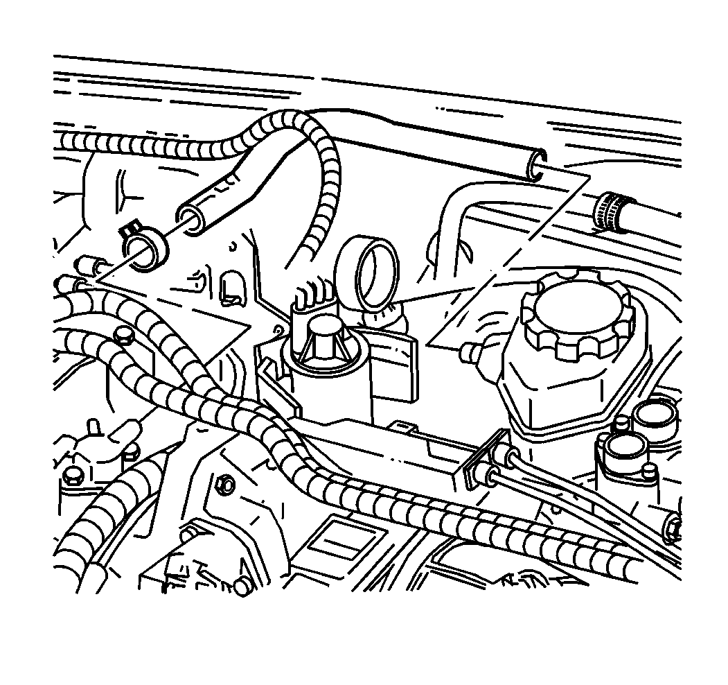
- Remove the vacuum hose from the vacuum check valve. Reposition the vacuum hose.
- Remove the knee bolster. Refer to Knee Bolster Replacement in Instrument Panel, Gages and Console.
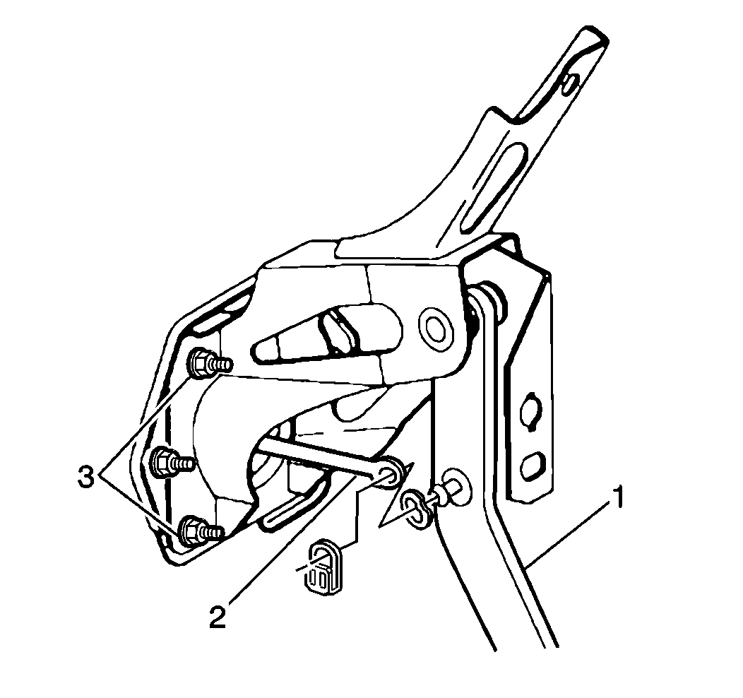
- Remove the booster push pin retaining clip and washer (2) from the brake pedal assembly.
- Remove the brake booster push rod (2) from the brake pedal (1).
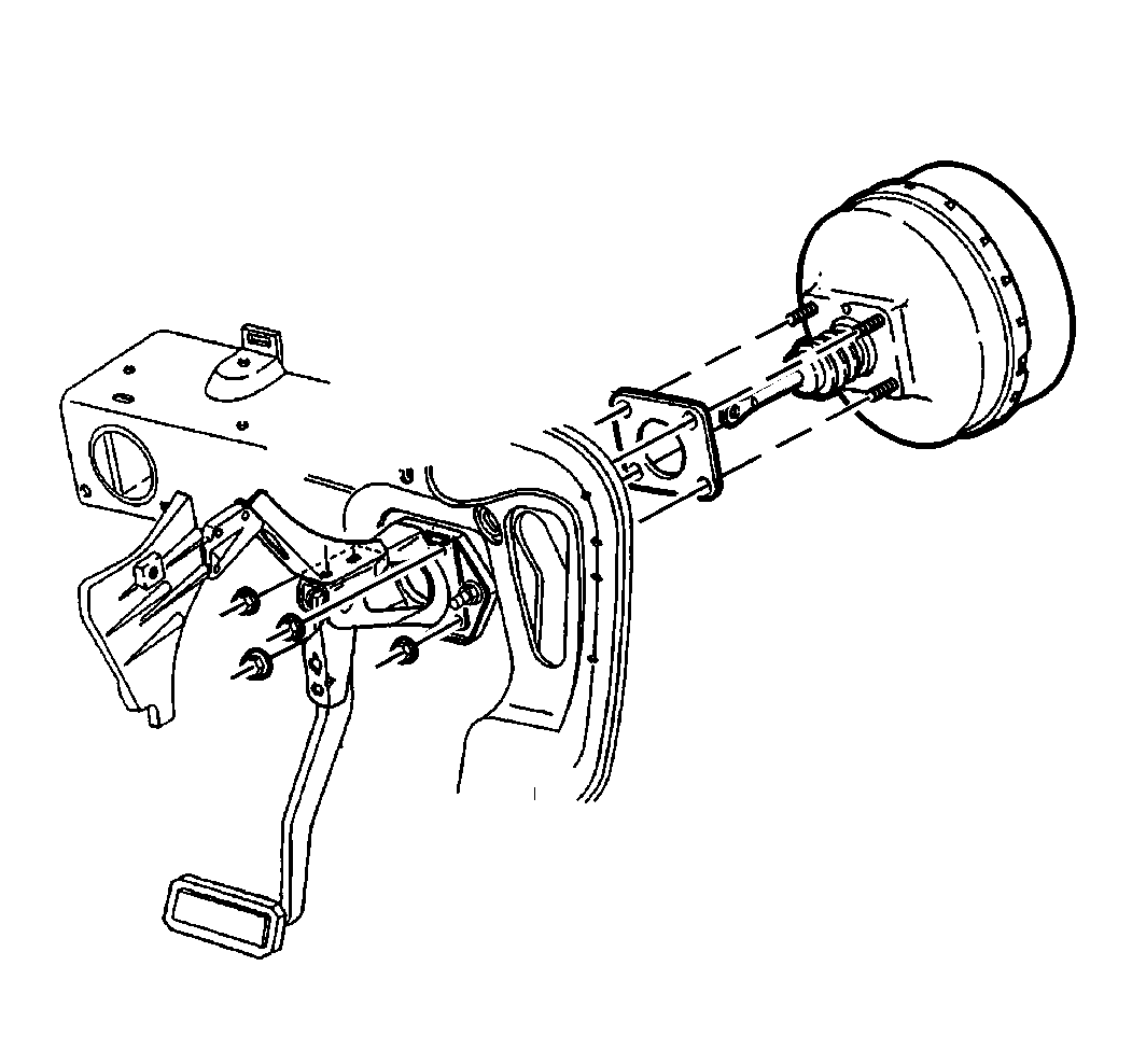
- Remove the brake booster mounting nuts.
- Remove the 2 front engine mounts, nuts and bolts. Refer to Engine Mount Strut Replacement-Left and Engine Mount Strut Replacement-Right in Engine Mechanical -3.4L.
- Rotate the engine forward to gain access to the brake booster removal. Refer to Rotating the Engine for Service Access in Engine Mechanical -3.4L.
- Remove the brake booster.
Caution: Refer to Brake Fluid Irritant Caution in Cautions and Notices.
Notice: Refer to Brake Fluid Effects on Paint and Electrical Components Notice in Cautions and Notices.


Installation Procedure
Caution: When replacing the power booster brake, make sure that the cruise control cable is not routed between the booster and the cowl. If the cable is damaged or pinched, it must be replaced. Failure to do this could result in personal injury.
- Position the brake booster to the cowl and the mounting plate.
- Install the brake booster mounting nuts.
- Install the master cylinder. Refer to Master Cylinder Replacement.
- Install the brake booster push rod (2) to the brake pedal (1). Install the washer and retaining clip.
- Adjust the stop lamp switch. Refer to Stop Lamp Switch Adjustment in Lighting Systems.
- Install the knee bolster. Refer to Knee Bolster Replacement in Instrument Panel, Gages and Console.
- Rotate the engine back and install the engine mounts, bolts, nuts. Refer to Rotating the Engine for Service Access in Engine Mechanical -3.4L.
- Install the vacuum hose to the check valve.
- Install the ABS module bracket and module. Refer to Brake Pressure Modulator Valve (BPMV) Replacement in Antilock Brake Systems.
- Connect the brake lines to the module.
- Connect the electrical connector to the ABS module and clip the electrical harness to the bracket.
- Install the brake master cylinder and connect the brake lines. Refer to Master Cylinder Replacement.
- Connect fluid level sensor switch on the master cylinder.
- Install the fuel lines to the pipes and the vapor line. Refer to Fuel Hose/Pipes Replacement-Engine Compartment.
- Install the heater cross over pipe. Refer to Heater Hose Replacement-Inlet in HVAC Systems-Manual.
- Install the air cleaner and duct assembly. Refer to Air Cleaner Assembly Replacement in Engine Controls -3.4L.
- Install the PCM. Refer to Powertrain Control Module (PCM) Replacement in Body and Accessories.
- Install the PCM cover.
- Install the left front cross brace. Refer to Brace Replacement-Front Fender Upper Diagonal-Left in Body and Accessories.
- Install cruise control bracket and the cruise control module. Refer to Cruise Control Module Replacement in Body and Accessories.
- Install the coolant reservoir. Refer to Coolant Recovery Reservoir Replacement in Engine Controls.
- Fill and bleed cooling system. Refer to Draining and Filling Cooling System in Engine Cooling.
- Bleed the brake system. Refer to Hydraulic Brake System Bleeding.

Notice: Refer to Fastener Notice in Cautions and Notices.
Tighten
Tighten the brake booster mounting nuts to 25 N·m (18 lb ft).

Notice: Proper stoplamp switch adjustment is essential. Improper stoplamp switch adjustment may cause brake drag, heat buildup and excessive brake lining wear.
