Engine Mount Replacement Right Side
Tools Required
J 28467-B , DW-117 (DW-110-060) Engine Assembly Support Fixture
Removal Procedure
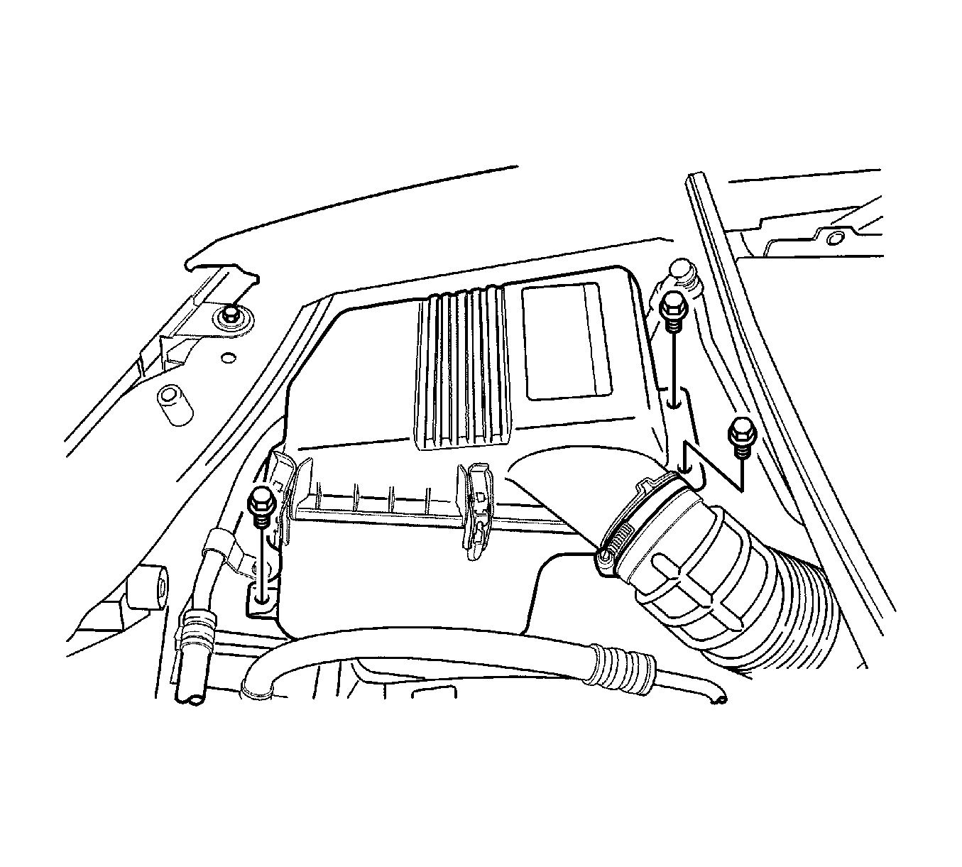
- Remove the air filter housing bolts.
- Remove the air filter housing assembly.
- Support the engine assembly using the EN 47519 .
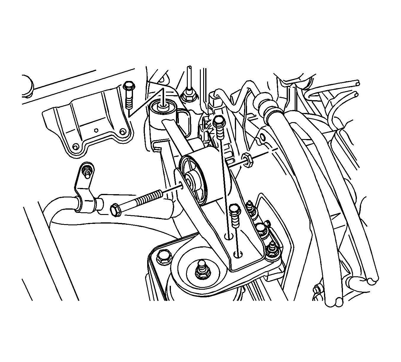
- Remove the reaction upper rod and the reaction upper rod bracket bolts.
- Remove the reaction upper rod and the reaction upper rod bracket.
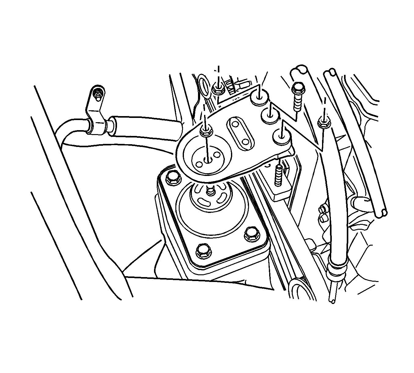
- Remove the engine mount bracket retaining bolt/nuts.
- Remove the engine mount bracket.
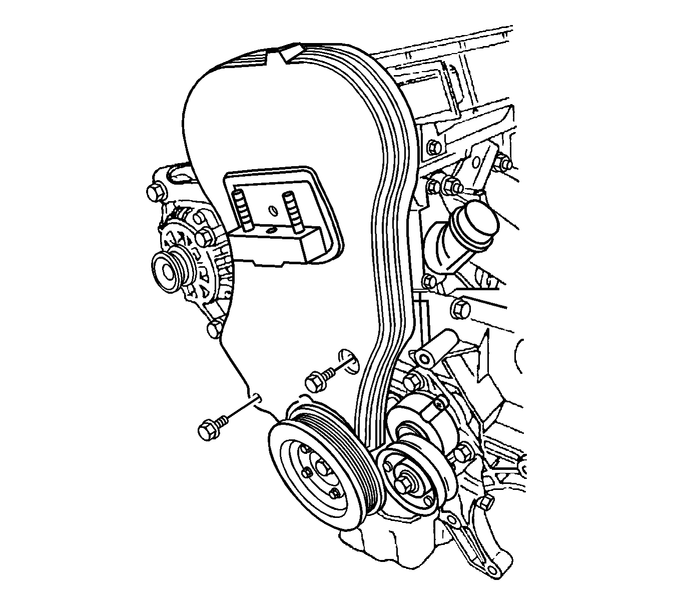
- Remove the serpentine accessory drive belt. Refer to Power Steering Pump Belt Replacement .
- Remove the front timing belt cover bolts and the front timing belt cover.
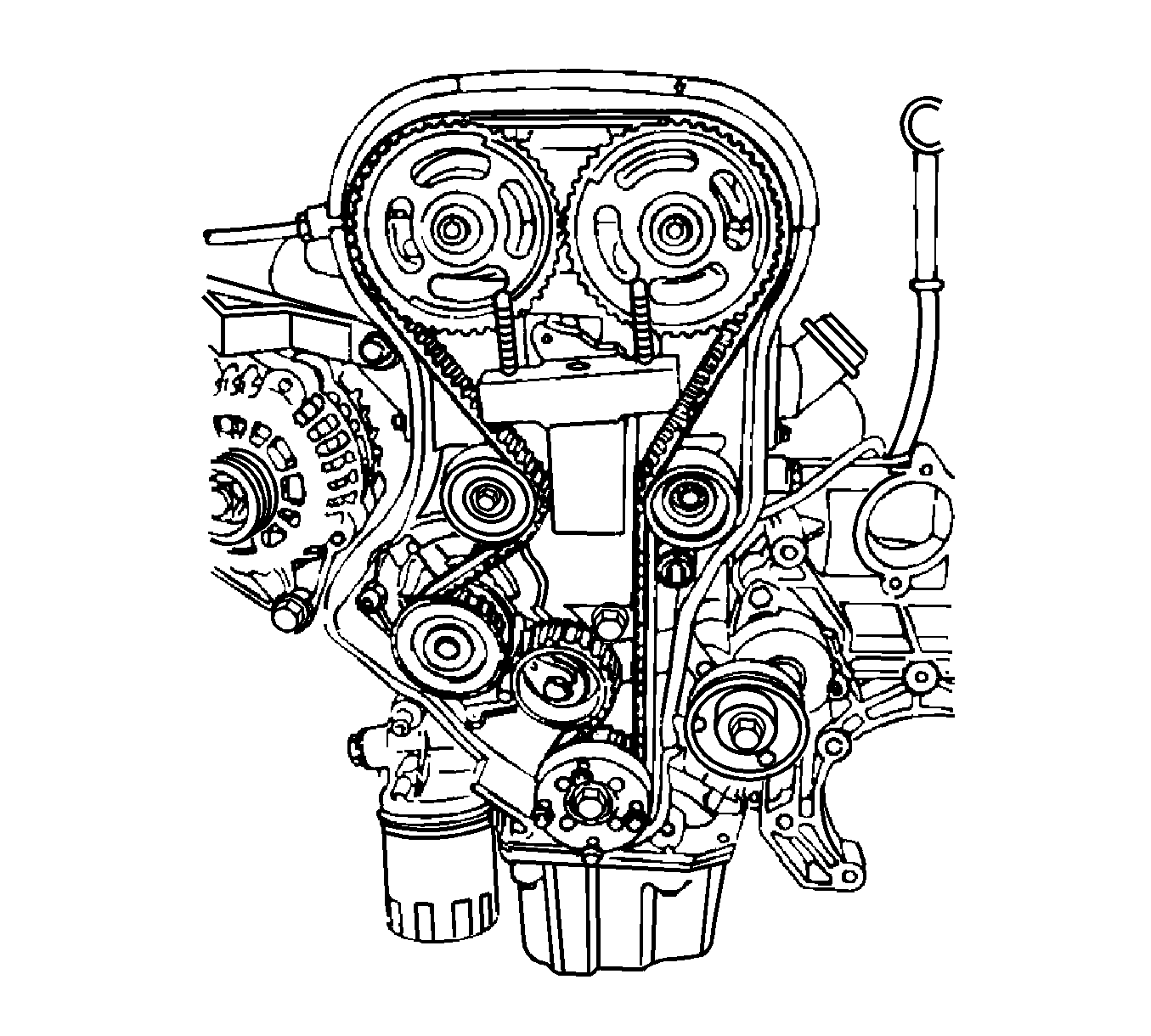
- Align the crankshaft pulley timing mark with the pointer, and the camshaft gears with the timing marks on the rear cover, by turning the crankshaft gear bolt.
- Loosen the timing belt automatic tensioner bolt.
- Turn the hex-key tab to relieve the belt tension.
- Remove the timing belt.
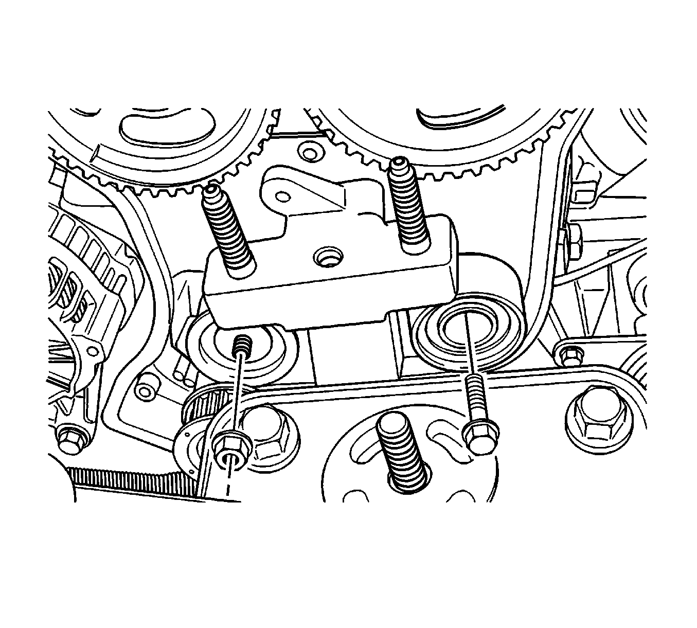
- Remove the timing belt idler pulley bolt/nut.
- Remove the timing belt idler pulleys.
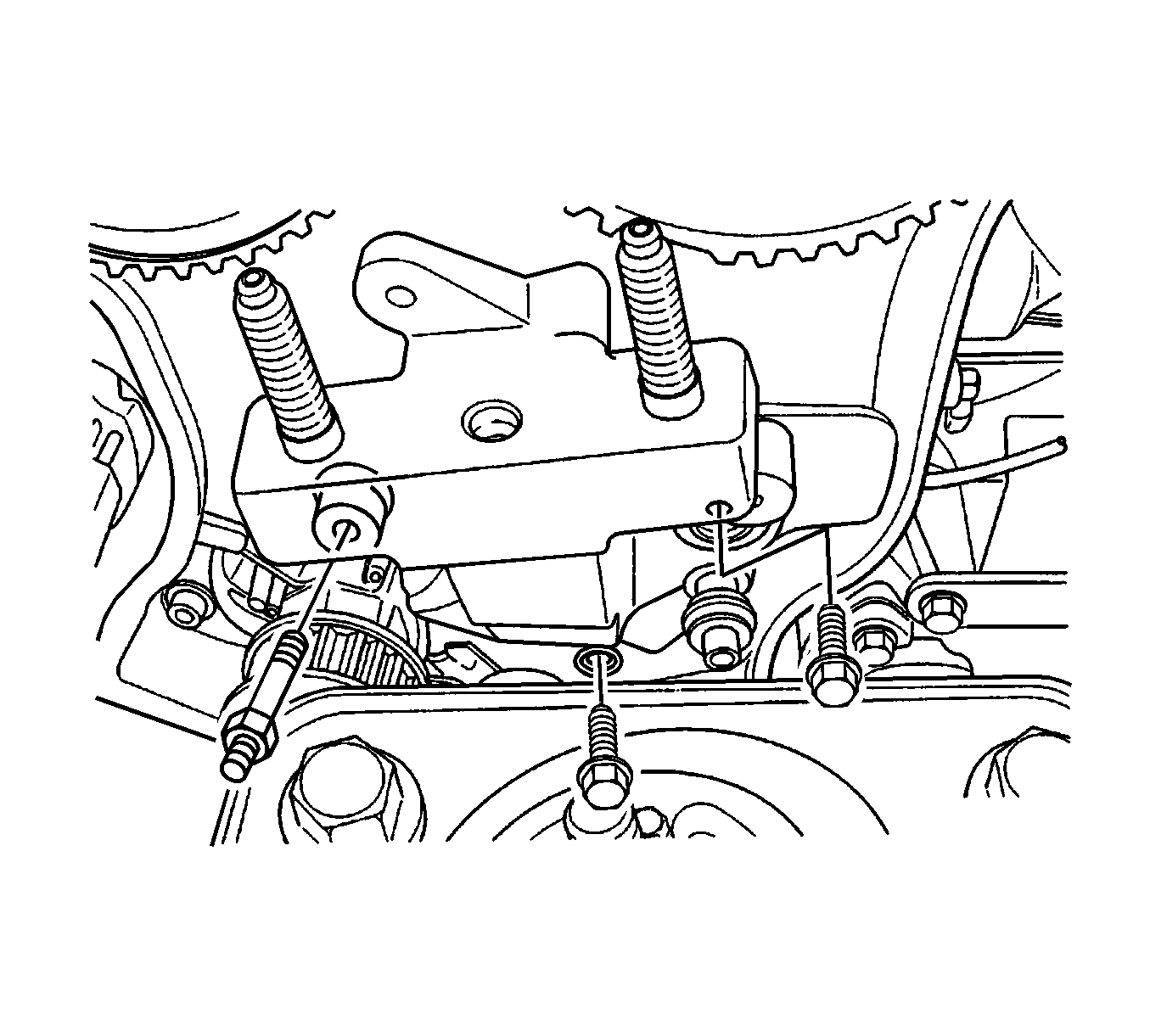
- Remove the engine mount retaining bolts.
- Remove the engine mount.
Notice: Broken engine mountings can cause misalignment of certain drive-train components. Misalignment of drive-train components causes eventual destruction of the drive-train components.
If one engine mount breaks, the rest of the engine mounts will have increased stress put on them. This could cause the rest of the engine mounts to break.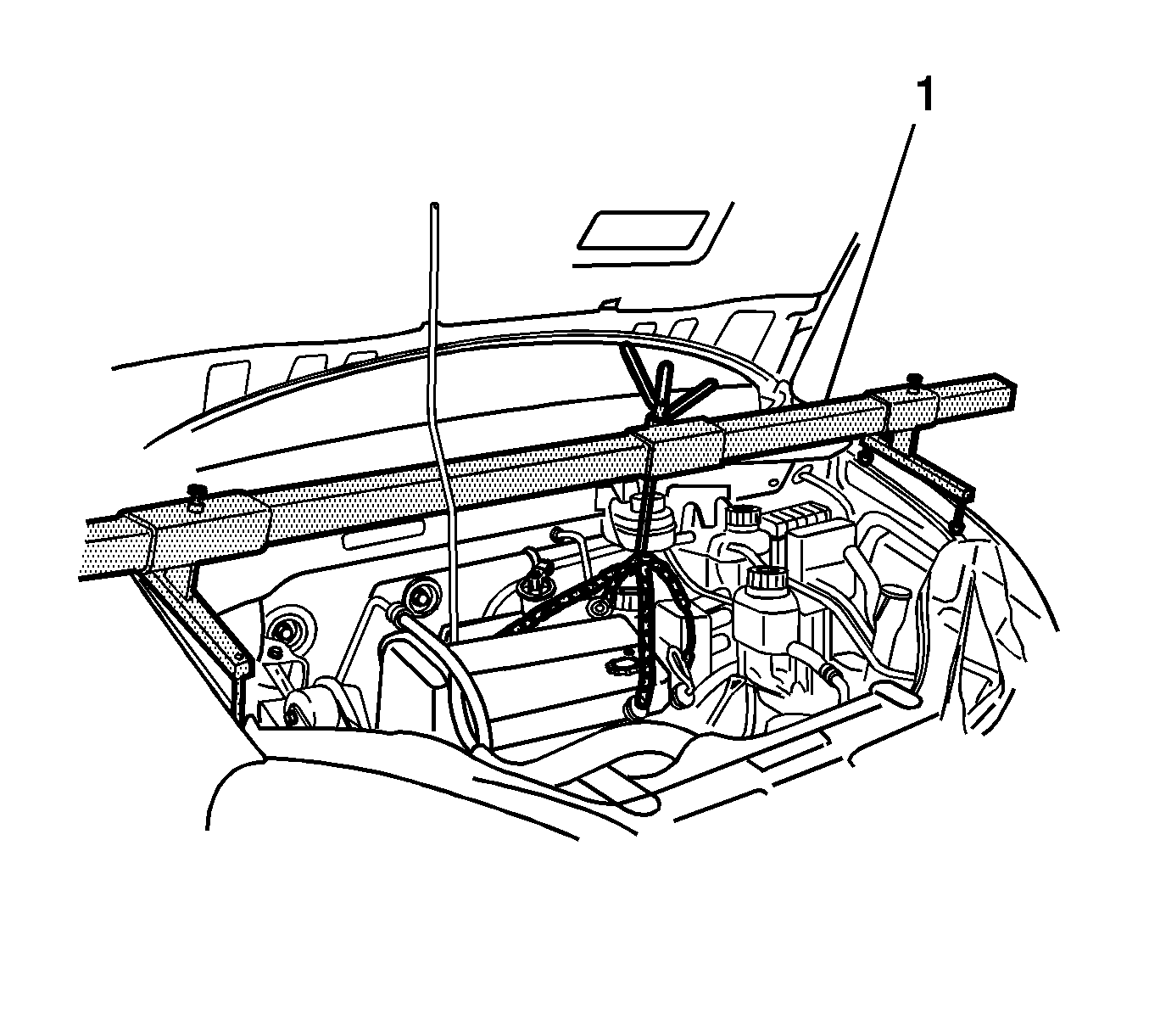
Notice: When raising or supporting the engine for any reason, do not use a jack under the oil pan, any sheet metal, or crankshaft balancer. Jacking against the oil pan may cause it to crack or break.
Notice: Do not use belt dressing on the drive belt. Belt dressing causes the breakdown of the composition of the drive belt. Failure to follow this recommendation will damage the drive belt.
Installation Procedure
- Install the engine mount.
- Install the engine mount retaining bolts.
- Install the timing belt idler pulleys.
- Install the timing belt idler pulley bolt/nut.
- Install the timing belt.
- Turn the hex-key tab to tighten the belt tension.
- Tighten the timing belt automatic tensioner bolt.
- Install the front timing belt cover bolts and the front timing belt cover.
- Install the serpentine accessory drive belt. Refer to Power Steering Pump Belt Replacement .
- Install the engine mount bracket.
- Install the engine mount bracket retaining bolt/nuts.
- Install the reaction upper rod and the reaction upper rod bracket.
- Install the reaction upper rod and the reaction upper rod bracket bolts.
- Remove the EN 47519 .
- Install the air filter housing assembly.
- Install the air filter housing bolts.

Notice: Refer to Fastener Notice in the Preface section.
Tighten
Tighten the engine mount attaching bolts to 55 N·m (41 lb ft).

Tighten
Tighten the idler pulley bolt/nut to 25 N·m (18 lb ft).

Tighten
Tighten the timing belt automatic tensioner bolt to 25 N·m (18 lb ft).


Tighten
Tighten the bracket retaining bolt/nuts to 60 N·m (44 lb ft).

Tighten
Tighten the reaction upper rod bracket bolts to 75 N·m (55 lb ft).

Notice: When raising or supporting the engine for any reason, do not use a jack under the oil pan, any sheet metal, or crankshaft balancer. Jacking against the oil pan may cause it to crack or break.

Engine Mount Replacement Lower
Removal Procedure
- Raise and suitable support the vehicle. Refer to Lifting and Jacking the Vehicle in General Information.
- Remove the front fascia splash shield and engine under cover. Refer to Engine Cover Replacement in Frame and Underbody.
- Remove the lower engine bracket bolt/nut.
- Remove the lower engine bracket.
- Remove the lower engine mount bolt.
- Remove the lower engine mount.


Installation Procedure
- Install the lower engine mount.
- Install the lower engine mount bolt.
- Install the engine mount bracket.
- Install the engine mount bracket bolt/nut.
- Install the front fascia splash shield and engine under cover. Refer to Engine Cover Replacement in Frame and Underbody.
- Lower the vehicle.

Notice: Refer to Fastener Notice in the Preface section.
Tighten
Tighten the engine mount bolt to 55 N·m (41 lb ft).

Tighten
Tighten the engine mount bracket bolt/nut to 69 N·m (49 lb ft).
