GM Service Manual Online
For 1990-2009 cars only

Air Conditioning

Vehicle air conditioning is the cooling, refrigeration, heating, and ventilation of the air in the passenger compartment. Refrigeration is accomplished by making practical use of the 3 laws of nature. These laws of nature and their practical application are as follows:

    • Heat transfer
    • Latent heat of vaporization
    • Effect of pressure on boiling or condensation

Heat Transfer

The principle of heat transfers are that the heat always flow from hot to cold, the rate of heat transfer will increase as the difference in temperature between 2 objects increases, and the mass of an object remains the same regardless of its heat contents.

Latent Heat of Vaporization

Everything in the world is composed of matter, and the matter exists in one of following states:

    • Solid
    • Liquid
    • Vapor

When a liquid boils, it changes to vapor and absorbs heat without raising the temperature of the resulting vapor.

When the vapor condenses, it changes back to a liquid and gives off heat without lowing the temperature of the resulting liquid.

Effect of Pressure on Boiling or Condensing

When the pressure on the liquid or vapor changes, the boiling point changes. Increasing the pressure increases the boiling point, while the boiling point decreased by decreasing the pressure on the liquid or vapor.

Another effect of the compression is an increase in temperature even though heat has not been added. For example, if you compress the refrigerant R-134a from 206-1206 kPa (30-175 psi), the temperature of vapor will increase from 0-54°C (32-130°F) and boiling point increase. Condensing point also will increase.

The V5 A/C System

The V5 variable displacement compressor, along with the thermal expansion valve on the evaporator, constitutes a largely self regulating system. There is no pressure cycling switch, no high and low pressure cutoff switch. The compressor clutch is controlled by the electronic control module (ECM), which receives data from various engine systems and the pressure transducer located in the high-pressure refrigerant pipe. In normal operation, the clutch is engaged continuously. Should one of the monitored conditions become abnormal, the ECM will disengage the compressor clutch until normal operation is restored. The abnormal conditions under which the ECM will disengage the compressor clutch are the following:
    • Wide open throttle
    • High engine coolant temperature
    • High engine RPM
    • Refrigerant low pressure
    • Refrigerant high pressure

System Components - Functional

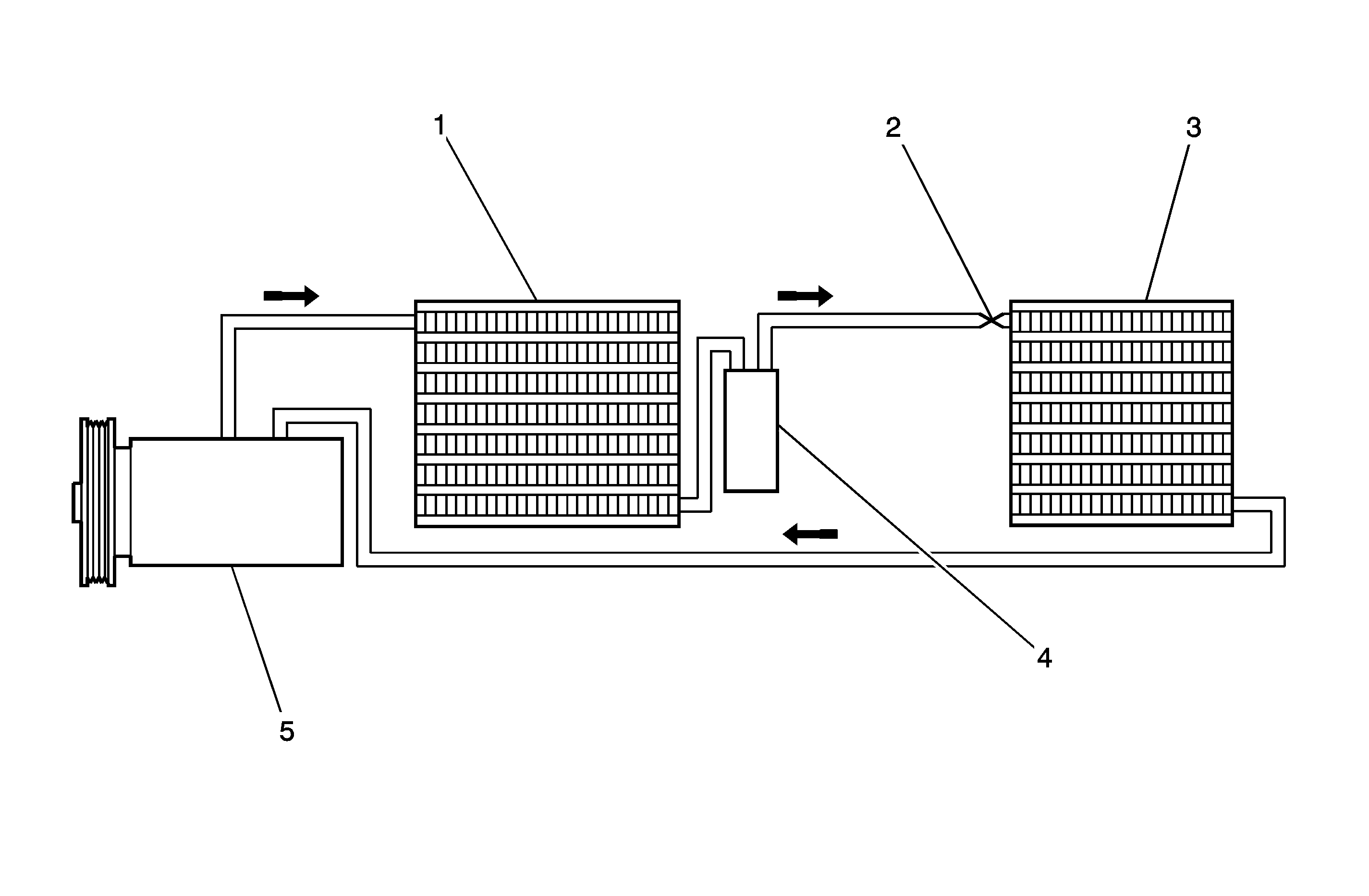
A/C System - Typical


Object Number: 1262756  Size: MF
(1)Condenser
(2)Expansion Valve
(3)Evaporator
(4)Receiver-Drier
(5)Compressor

Compressor

All compressors are belt-driven from the engine crankshaft through the compressor clutch pulley. The compressor pulley rotates without driving the compressor shaft until an electromagnetic clutch coil is energized. When voltage is applied to energize the clutch coil, the clutch plate and hub assembly is drawn rearward toward the pulley. The magnetic force locks the clutch plate and pulley together as one unit to drive the compressor shaft.

As the compressor shaft is driven, it compresses the low pressure refrigerant vapor from evaporator into high-pressure, high temperature vapor. The refrigerant oil that is used to lubricate the compressor is carried with the refrigerant.

Pressure Relief Valve

The compressor is equipped with a pressure relief valve which is placed in the system as a safety factor. Under certain conditions, the refrigerant on the discharge side may exceed the designed operating pressure at approximately at 3 171-4 137 kPa (460-600 psi) in an R-134a system. Conditions that might cause this valve to open, such as a defective pressure transducer, an inoperative cooling fan, etc., should be corrected. The refrigerant oil and the refrigerant should be replaced as necessary.

Condenser Core

The condenser assembly in front of the radiator consists of coils, which carry the refrigerant and cooling fins that provide the rapid transfer of heat. The air passing through the condenser cools the high-pressure refrigerant vapor and causes it to condense into a liquid.

Expansion Valve

The expansion valve is attached to the evaporator core, inside the heater/air distributor case under the instrument panel.

The expansion valve can fail in 3 different positions:

    • Open
    • Closed
    • Restricted

An expansion valve that fails in open position will result in a noisy A/C compressor or no cooling. The cause can be a broken spring, a broken ball, or excessive moisture in the A/C system. If the spring or the ball are found to be defective, replace the expansion valve. If excessive moisture is found in the A/C system, recycle the refrigerant.

An expansion valve that fails in the closed position will result in low suction pressure and no cooling. This may be caused by a failed power dome or excessive moisture in the A/C system. If the power dome on the expansion valve is founded to be defective, replace the expansion valve. If excessive moisture is found in the A/C system, recycle the refrigerant.

A restricted expansion valve will result in low suction pressure and no cooling. This may be caused by debris in the refrigerant system. If debris is believed to be the cause, recycle the refrigerant, replace the expansion valve, and replace the receiver-drier.

Evaporator Core

The evaporator is a device which cools and dehumidifies the air before it enters the vehicle. High pressure liquid refrigerant flows through the expansion tube, orifice, and becomes a low pressure gas in the evaporator. The heat in the air passing through the evaporator core is transferred to the cooler surface or the core, which cools the air.

As the process of heat transfer from the air to the evaporator core surface is taking place, any moisture, humidity, in the air condenses on the outside surface of the evaporator core and is drained off as water.

Receiver-Drier

The sealed receiver-drier assembly is connected between the condenser and evaporator. It acts as a refrigerant storing container, receiving liquid and some vapor and refrigerant oil from the condenser.

At the bottom of the receiver-drier is the desiccant, which acts as drying agent for the moisture that may have entered the system. An oil bleed hole is located near the bottom of the receiver-drier outlet pipe to provide an oil return path to the compressor. The receiver dryer is serviceable as an assembly.

Heater Core

The heater core heats the air before it enters the vehicle. Engine coolant is circulated through the core to heat the outside air passing over the pin of the core. The core is functional at all times and may be used to temper conditioned air in the A/C mode as well as in heat or the vent mode.

System Components - Control

Controller

The operation of the A/C system is controlled by the switches and knob on the control head. This console mounted controller contains following control knobs.

Rotary Temperature Control Knob

    • Actuates by cable
    • Raises the temperature of the air entering the vehicle by sliding to the right, or the red portion of the knob
    • Varies the mix of the fresh air from outside the vehicle with the heated air from inside the vehicle to suit individual performance

Rotary Mode Control Knob

    • Actuates by cable
    • Regulates the air distribution between the windshield, the instrument panel, and the floor vents

Rotary Blower Control Knob

    • Turns ON to operate the blower motor at 4 speeds
    • Turns OFF to stop the blower
    • Operates completely independently from both the mode control knob and temperature control knob
    • Changes the fan speed in any mode and at any speed

Push Inlet Air Control Knob

    • Operates by electricity
    • Switches between recirculating the passenger compartment air and bringing outside air into the passenger compartment
    • Is normally in fresh air mode
    • Illuminates the indicator lamp when in the recalculating mode

Push A/C Knob

    • Controls the A/C
    • Turns the A/C ON when the knob is pressed and the indicator lamp is illuminated--The rotary blower control knob must be in one of the its 4 positions for the A/C to function.

Pressure Transducer

Pressure transducer switching incorporates the functions of the high-pressure and the low-pressure cutout switches along with the fan cycling switch. The pressure transducer is located in high side liquid refrigerant line between the right strut tower and the air cleaner assembly. The output from this pressure transducer goes to the ECM which controls the compressor function based on the pressure signal.

Wide Open Throttle (WOT) Compressor Cutoff

During full throttle acceleration, the throttle position (TP) sensor sends a signal to the ECM, which then controls the compressor clutch.

V5 Compressor - General Description

Vehicles using the V5 compressor may have differences between installations in the mounting brackets, the drive system, the pulleys, the connections, and the system capacities. Basic overhaul procedures are similar between the compressors used on different vehicles.

When servicing the compressor, keep dirt and foreign material from getting on or into the compressor parts and the system. Clean tools and a clean work area are important for proper service. The compressor connections and outside of the compressor should be cleaned before performance of any on-vehicle repairs and before removal of the compressor. The parts must be kept clean at all times and any parts that are to be reassembled should be cleaned with trichloroethane, naphtha, stoddard solvent, kerosene, or equivalent solvents and dried with dry air. Use only lint-free cloths to wipe the parts.

Important: The oil drain plug must be removed and the oil drained through the plug opening to insure complete draining of oil from the compressor.

The operations described are based on bench overhaul with the compressor removed from the vehicle, except as noted. They have been prepared in the order of accessibility of the components. When a compressor is removed from the vehicle for servicing, the amount of oil remaining the compressor should be drained, measured, and recorded. This should then be discarded and new polyalkaline glycol (PAG) refrigerant oil added to the compressor.

V5 Compressor - Operation

The V5 is a variable displacement compressor that can match the automotive air conditioning demand under all conditions without cycling. The basic compressor mechanism is a variable angle wobble-plate with 7 axially oriented cylinders. The center of the control of the compressor displacement is a billows-actuated control valve located in the rear head of the compressor that senses compressor suction pressure.

The wobble-plate angle and the compressor displacement are controlled by the crankcase suction pressure differential. When the A/C capacity demand is high, the suction pressure will be above the control point. The valve will maintain a bleed from crankcase to suction. With no crankcase suction pressure differential, the compressor will have maximum displacement.

When the A/C capacity demand is lower and the suction pressure reaches the control point, the valve will bleed discharge gas in the crankcase and close off a passage from the crankcase to suction plenum. The angle of the wobble-plate is controlled by a force balance of 7 pistons. A slight elevation of the crankcase suction pressure differential creates total force on the piston resulting in a movement about the wobble-plate pivot pin that reduces the plate angle.

The compressor has a unique lubrication system. The crankcase suction bleed is routed through the rotating wobble-plate for lubrication of the wobble-plate bearing. The rotation acts as an oil separator that removes some of the oil from the crankcase suction bleed, rerouting it to the crankcase where it can lubricate the compressor mechanism.