Engine Replacement w/Automatic Transmission
Special Tools
J 45059 Angle Meter
Removal Procedure
- Disconnect the negative battery cable. Refer to Battery Negative Cable Disconnection and Connection .
- Remove the hood. Refer to Hood Replacement .
- Recover the air conditioning (A/C) system. Refer to Refrigerant Recovery and Recharging .
- Remove the drive belt. Refer to Drive Belt Replacement .
- Remove the radiator. Refer to Radiator Replacement .
- Relieve the fuel system pressure. Refer to Fuel Pressure Relief .
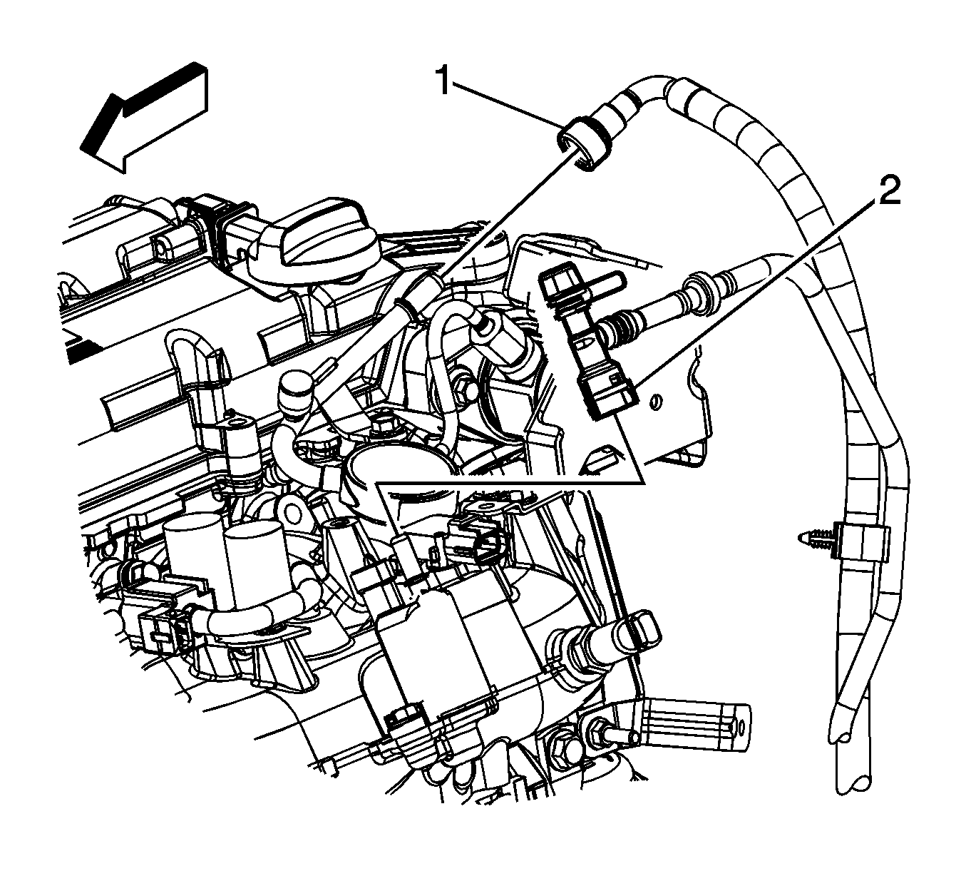
- Disconnect the evaporative emission (EVAP) canister purge solenoid tube from the valve (2). Refer to Plastic Collar Quick Connect Fitting Service .
- Disconnect the fuel feed pipe (1) from the fuel line. Refer to Metal Collar Quick Connect Fitting Service .
- Remove the charge air cooler inlet and outlet pipes. Refer to Charge Air Cooler Inlet Pipe Replacement and Charge Air Cooler Outlet Pipe Replacement .
- Remove the air inlet grille panel. Refer to Air Inlet Grille Panel Replacement .
- Remove the starter. Refer to Starter Motor Replacement .
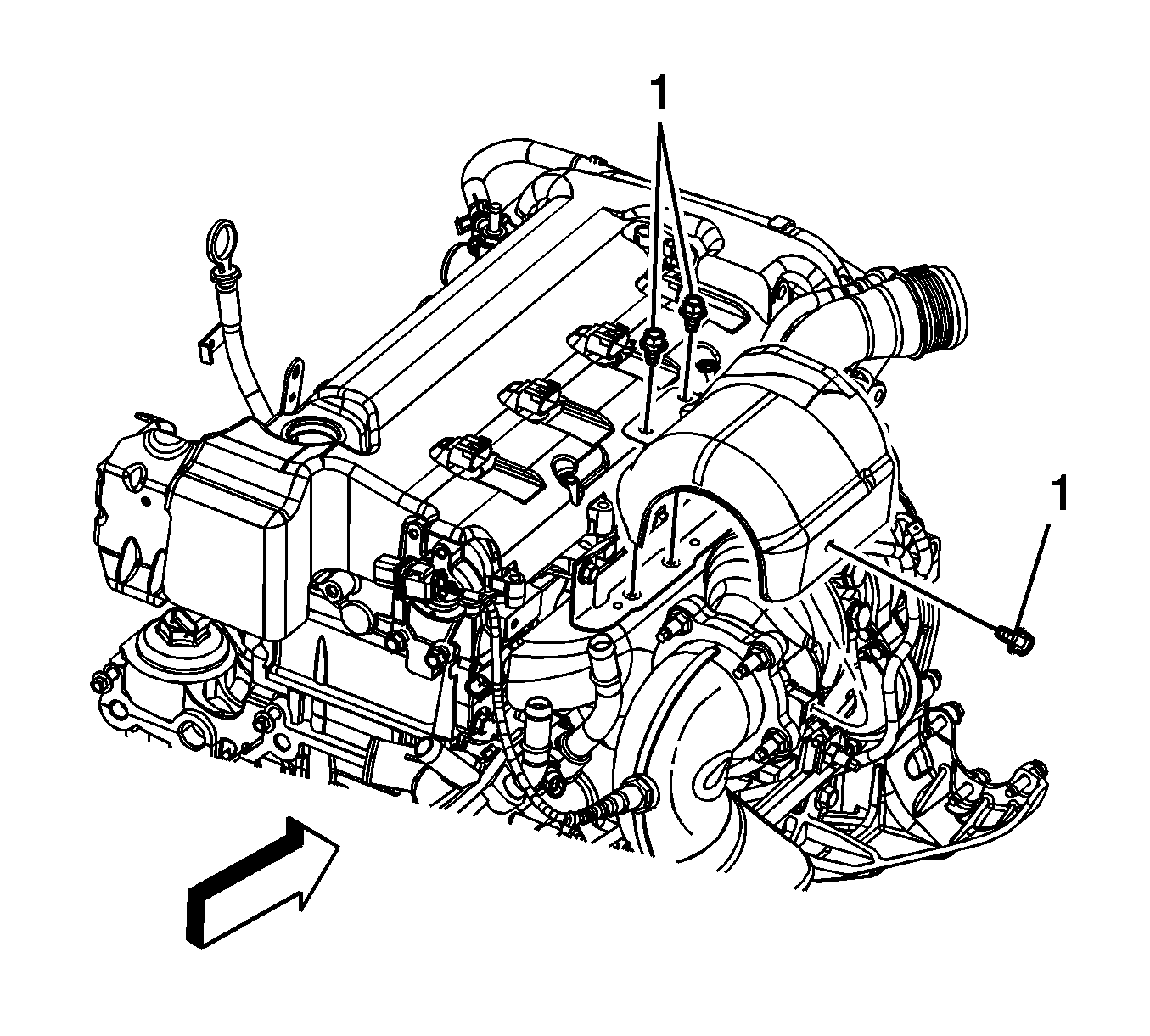
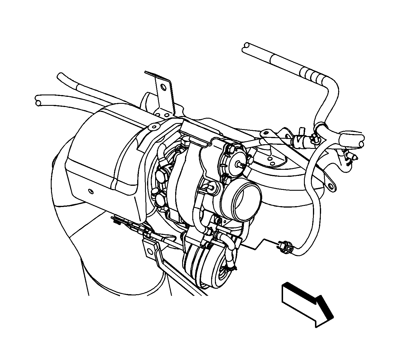
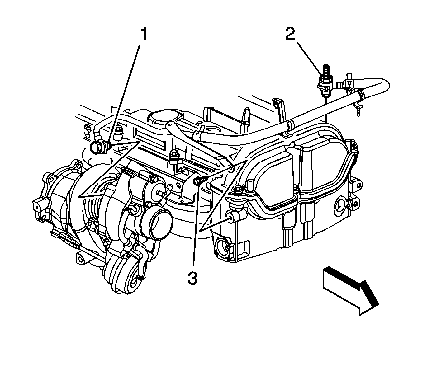
- Remove the turbocharger heat shield bolts (1) and shield.
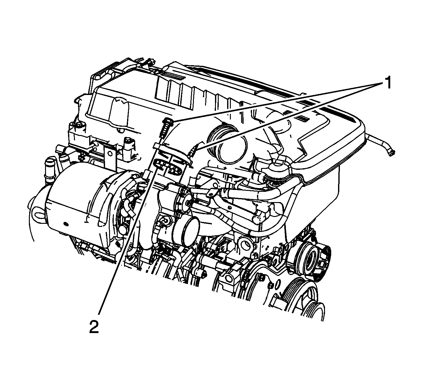
- Remove the charge air cooler pipe to turbocharger bolts (1).
- Remove the charge air cooler pipe and gasket (2) from the turbocharger.
- Cap or plug the turbocharger opening.
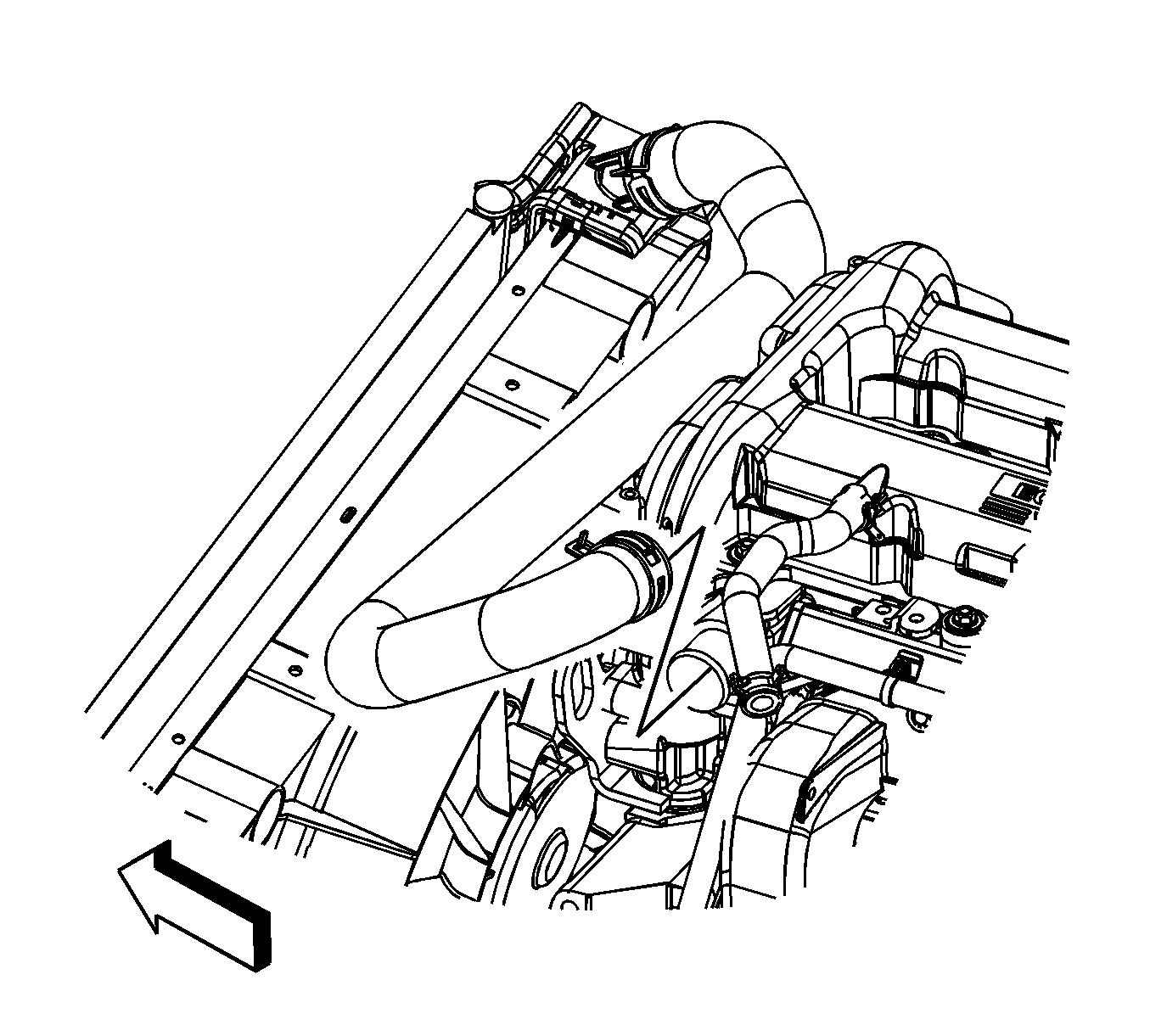
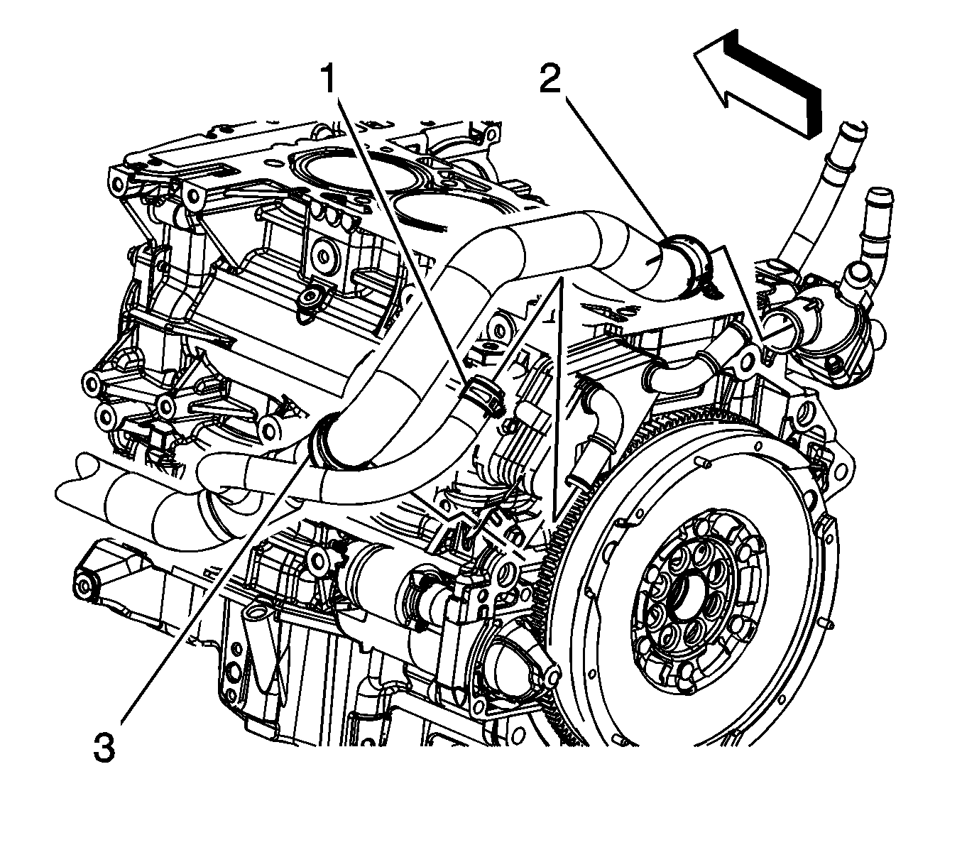
- Reposition the radiator inlet hose clamp at the engine.
- Remove the radiator inlet hose from the engine.
- Reposition the radiator inlet hose out of the way.
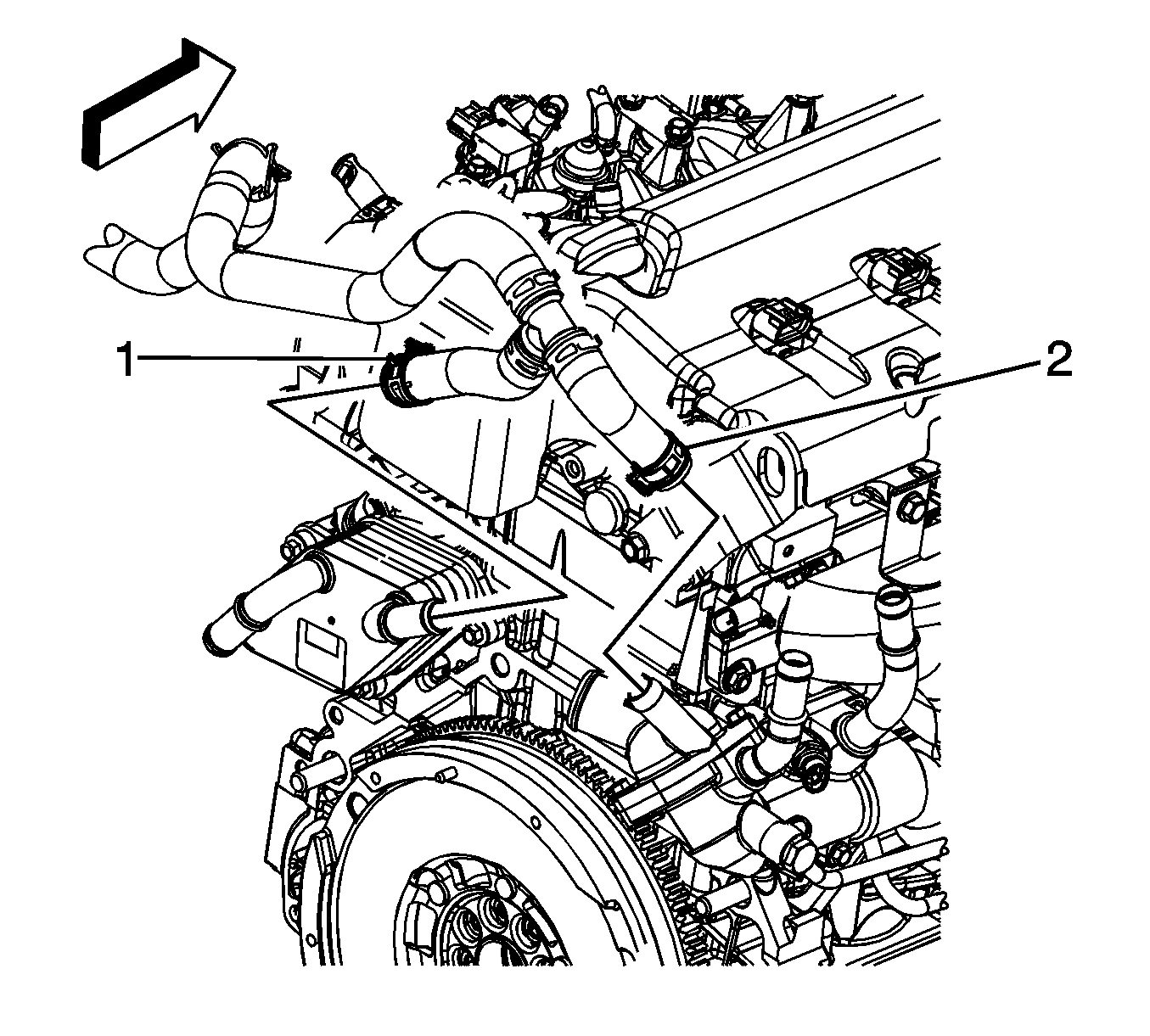
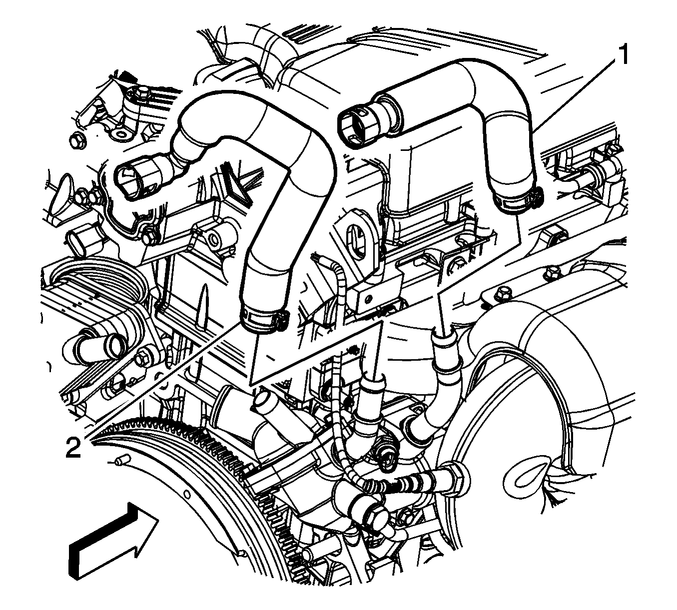
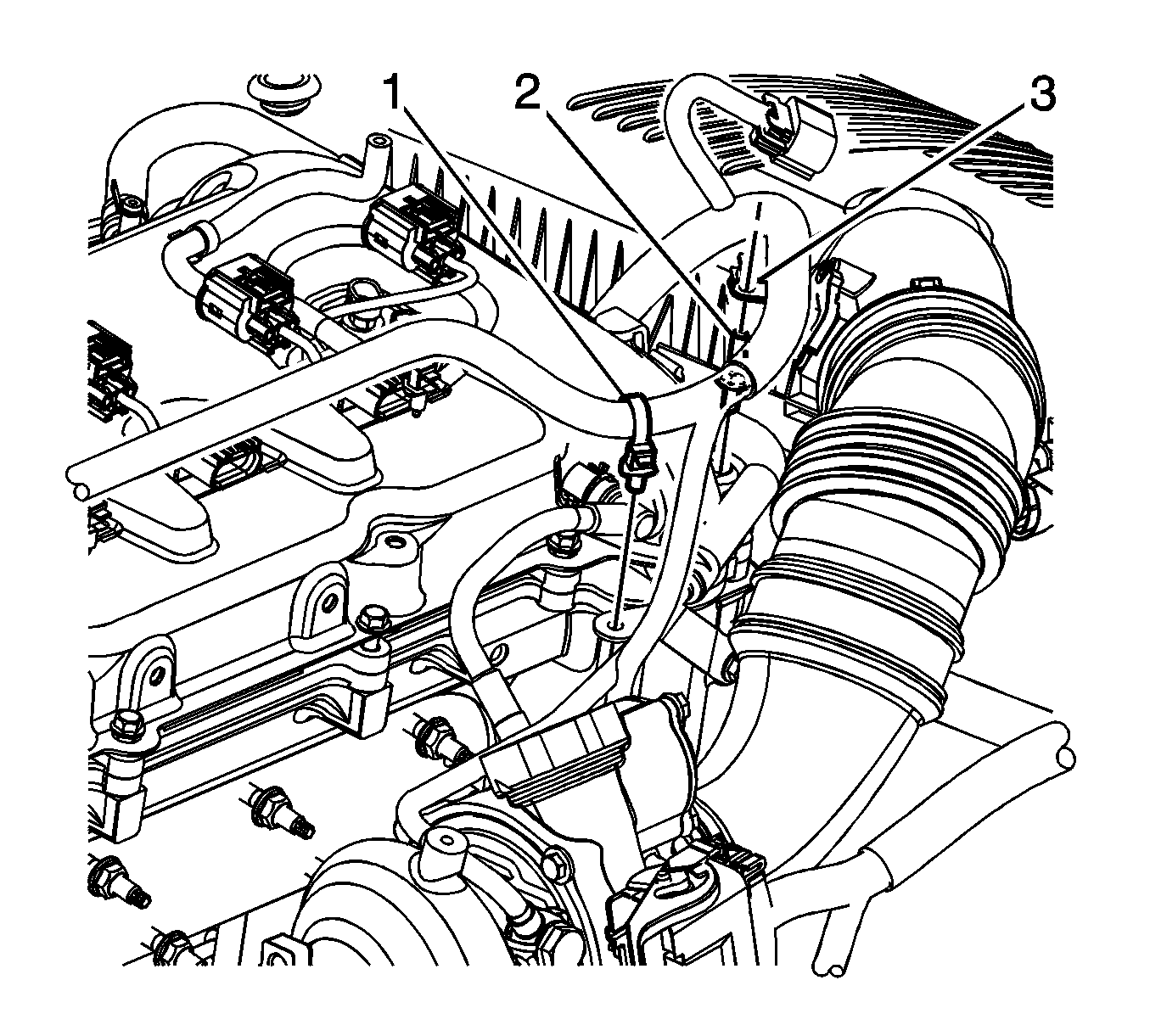
- Reposition the radiator outlet hose clamp (2) at the thermostat housing.
- Reposition the radiator outlet hose clamp (1) at the oil cooler.
- Remove the radiator outlet hose from the thermostat housing and oil cooler.
- Remove the radiator outlet hose clip (3) from the bracket.
- Reposition the radiator outlet hose out of the way.
- Reposition the surge tank outlet hose clamp (2) at the thermostat housing.
- Reposition the surge tank outlet hose clamp (1) at the oil cooler.
- Remove the surge tank outlet hose from the thermostat housing and oil cooler.
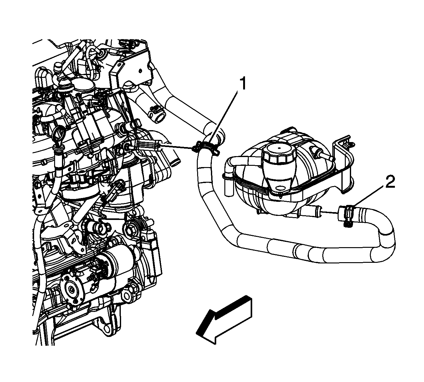
- Reposition the surge tank outlet hose clamp (2) at the surge tank.
- Remove the surge tank outlet hose from the surge tank.
- Remove the surge tank clip (1) from the oil level indicator tube bracket.
- Remove the surge tank outlet hose from the vehicle.
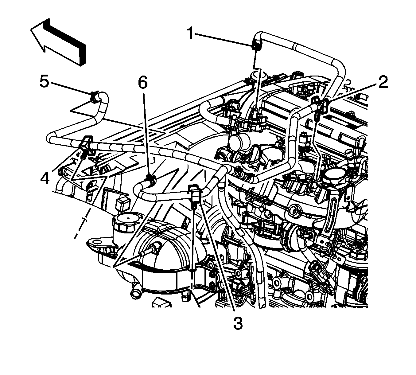
- Reposition the surge tank air bleed hose clamp (1) at the engine.
- Remove the surge tank air bleed hose clip (3) from the surge tank bracket.
- Remove the surge tank air bleed hose from the engine.
- Reposition the air bleed hose out of the way.
- Reposition the heater inlet and outlet hose clamps at the thermostat housing.
- Remove the heater inlet (1) and outlet (2) hoses from the thermostat housing.
- Raise and suitably support the vehicle. Refer to Lifting and Jacking the Vehicle .
- Drain the engine oil.
- Unbolt the catalytic converter from the exhaust pipe.
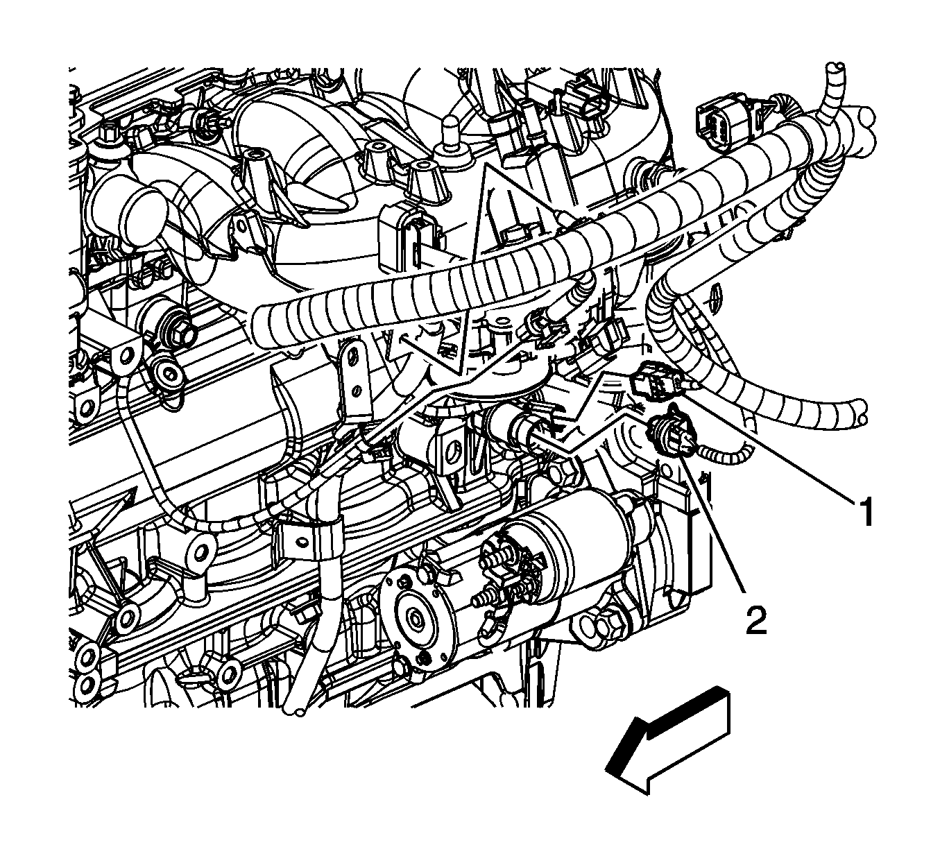
- Disconnect the engine wiring harness electrical connector (1) from the crankshaft position (CKP) sensor.
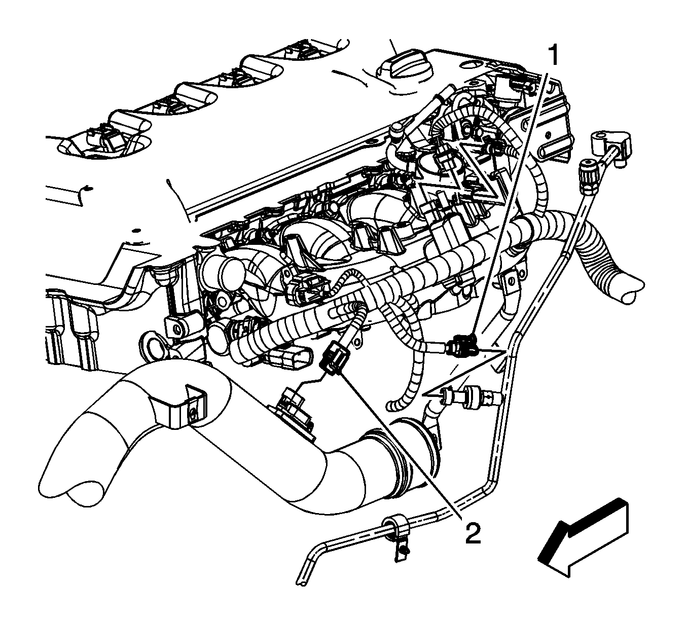
- Disconnect the engine wiring harness electrical connector (2) from the oil pressure sensor.
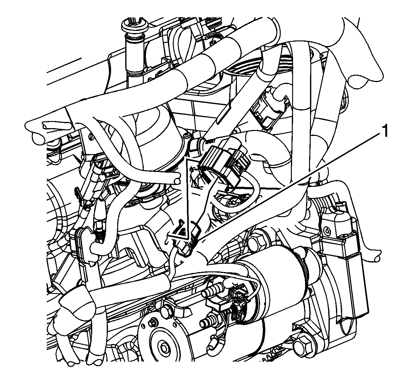
- Disconnect the engine wiring harness electrical connector (1) from the brake booster vacuum pump.
- Lower the vehicle.
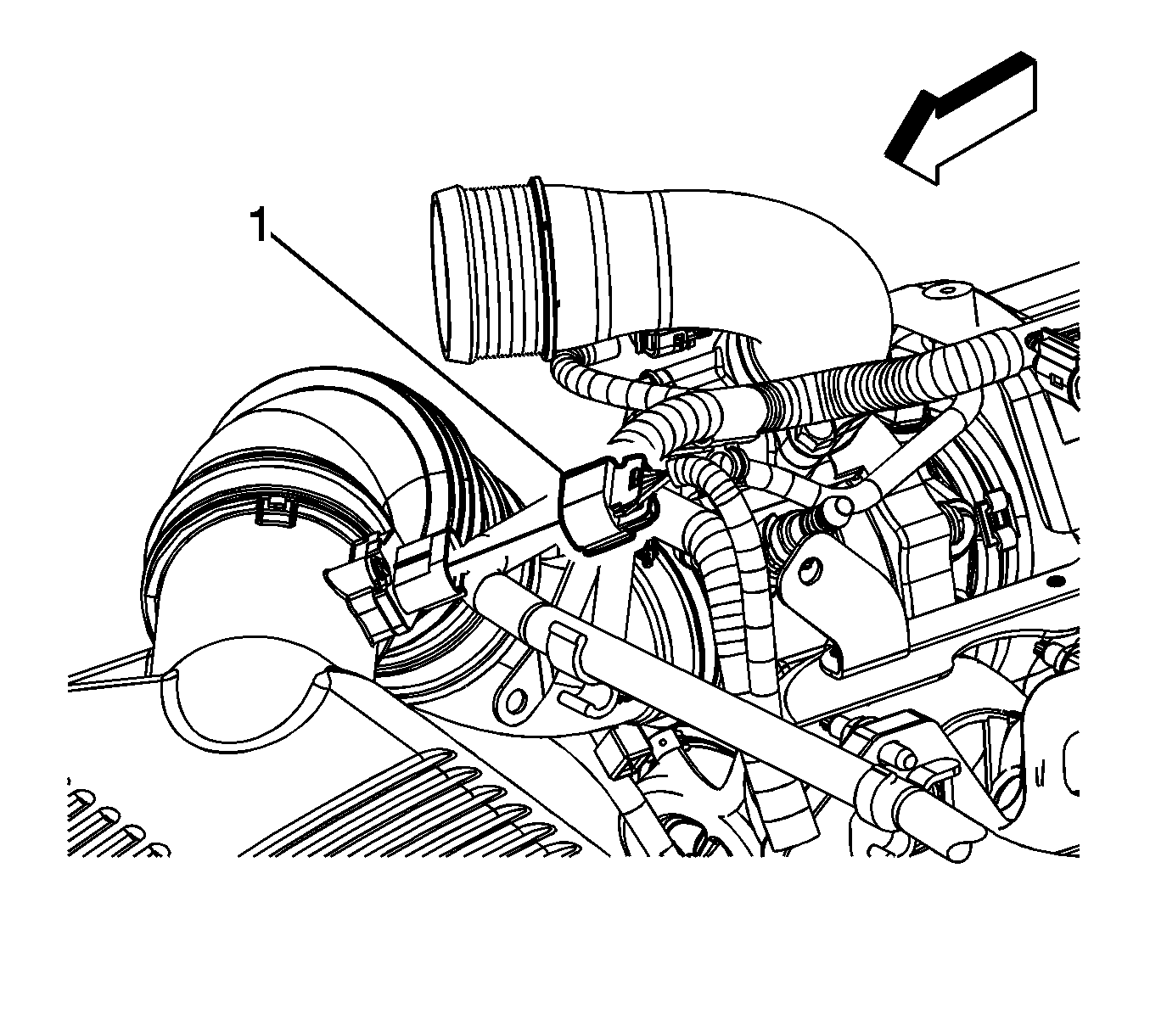
- Disconnect the engine wiring harness electrical connector (1) from the mass air flow (MAF) sensor.
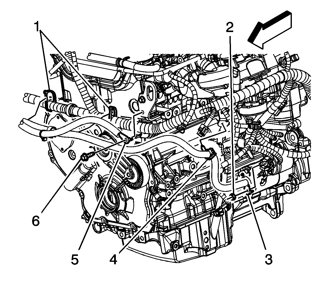
- Cut the engine harness tie straps (1).
- Remove the negative battery cable ground bolt (6) from the front engine lift bracket.
- Remove the negative battery cable ground terminal (5) from the engine lift bracket.
- Reposition the negative/positive battery cable out of the way.
- Disconnect the engine wiring harness electrical connector (1) from the transmission oil cooler pump.
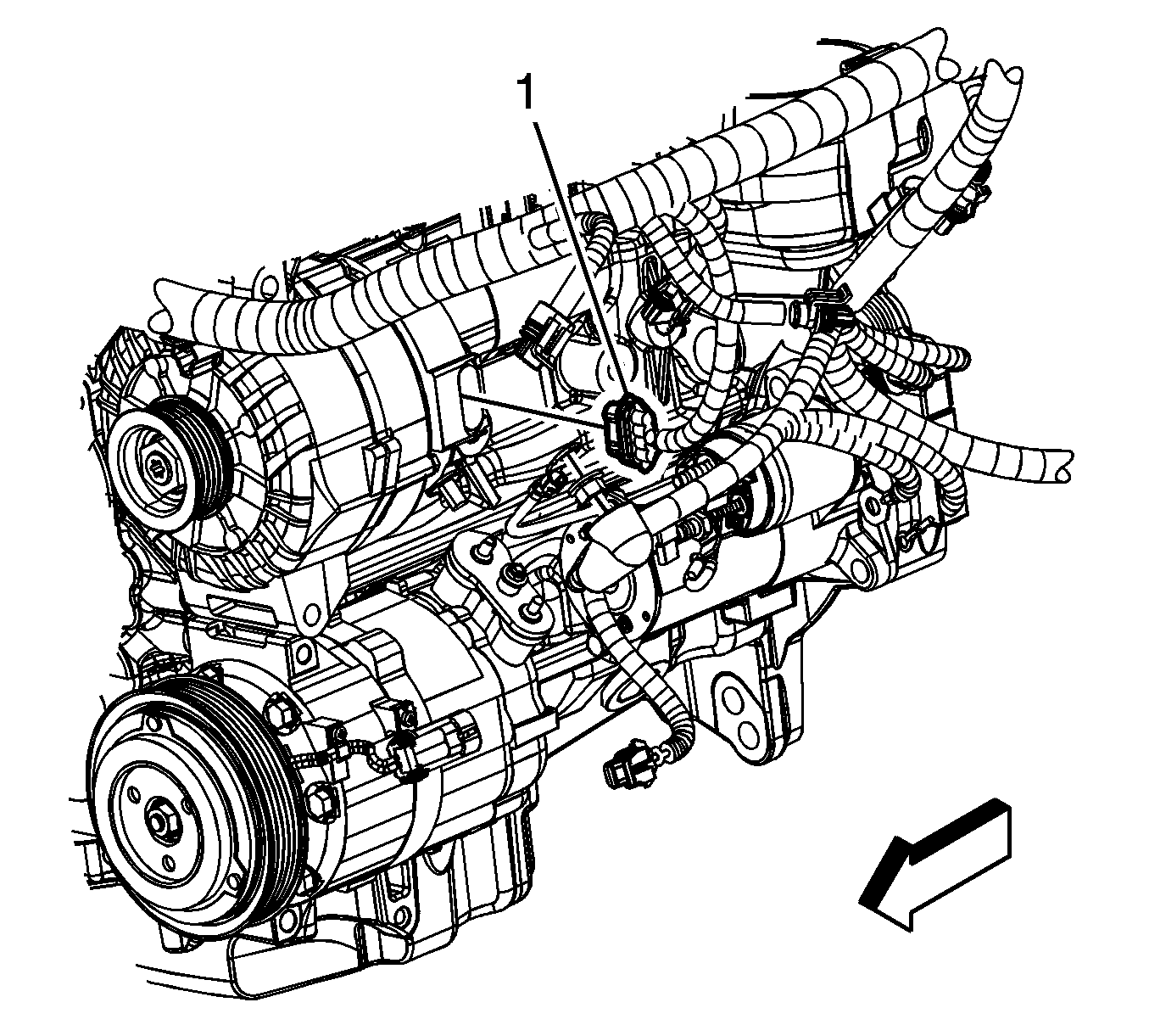
- Disconnect the engine wiring harness electrical connector (1) from the generator.
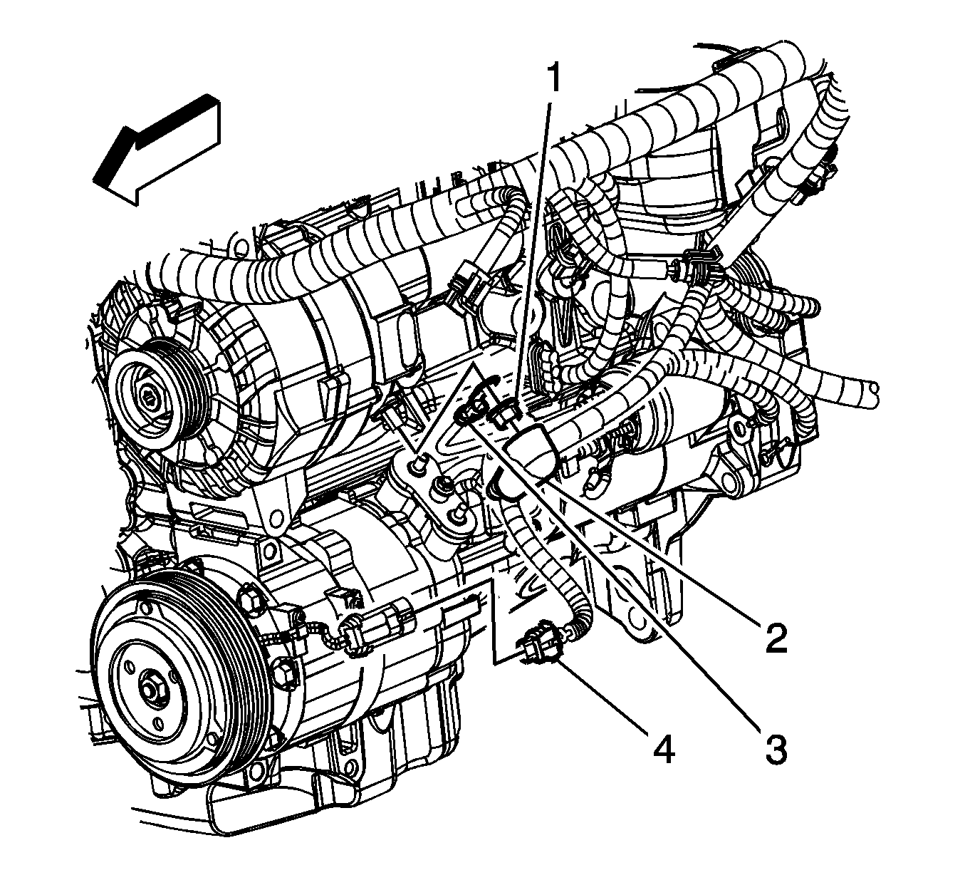
- Reposition the positive battery cable terminal boot (2).
- Remove the generator terminal nut (1).
- Remove the positive battery cable terminal (3) from the generator.
- Disconnect the engine wiring harness electrical connector (4) from the A/C compressor.
- Disconnect the engine wiring harness electrical connector (1) from the fuel injector jumper electrical connector.
- Disconnect the engine wiring harness electrical connector (2) from the knock sensor.
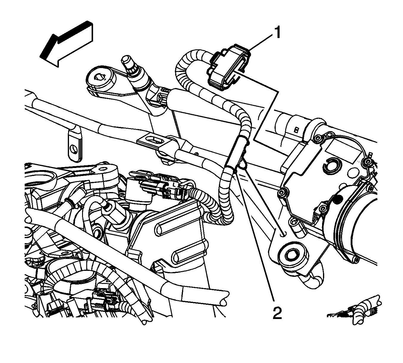
- Disconnect the engine wiring harness electrical connector (1) from the A/C refrigerant pressure sensor.
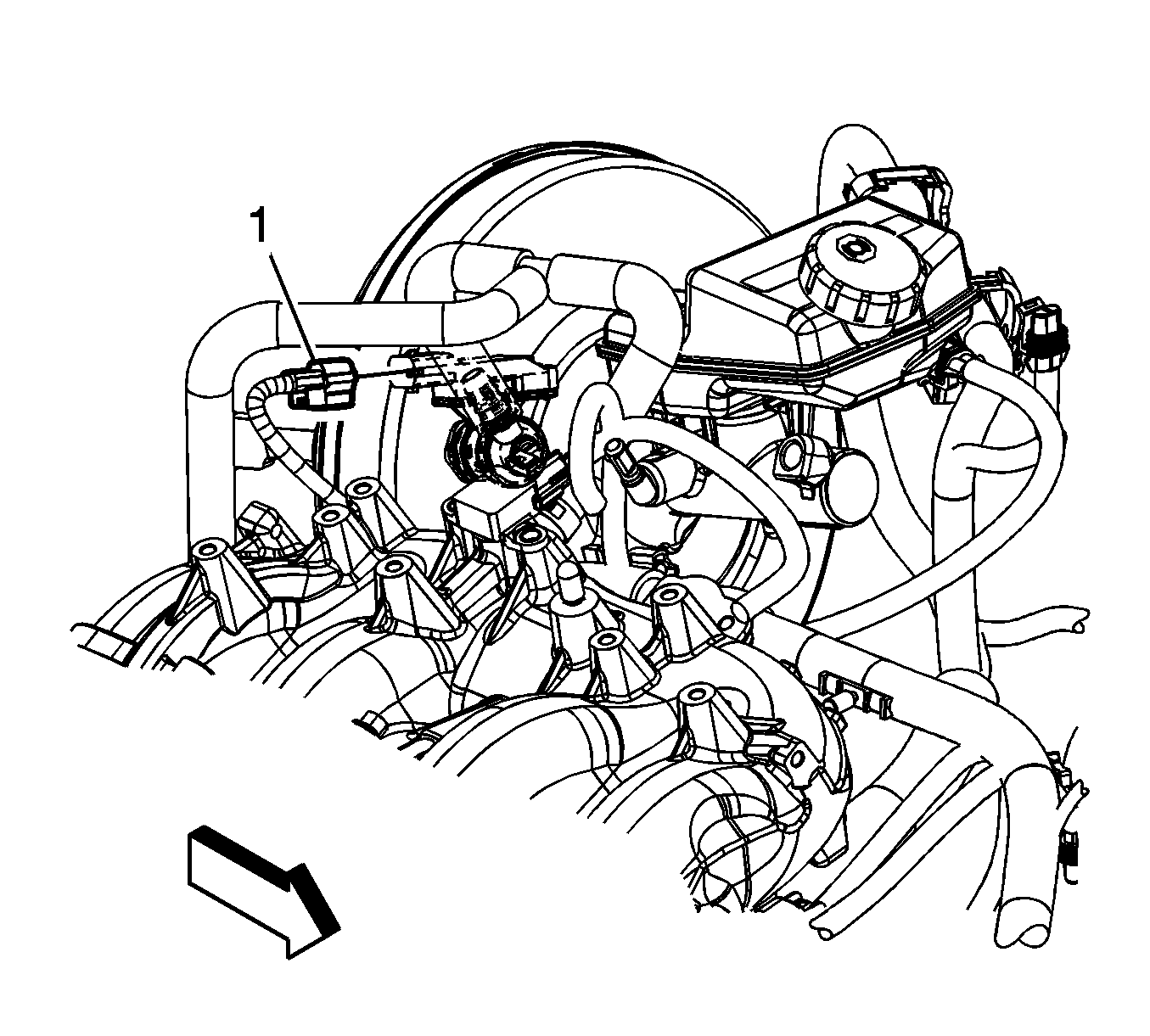
- Disconnect the engine wiring harness electrical connector (1) from the brake booster vacuum sensor.
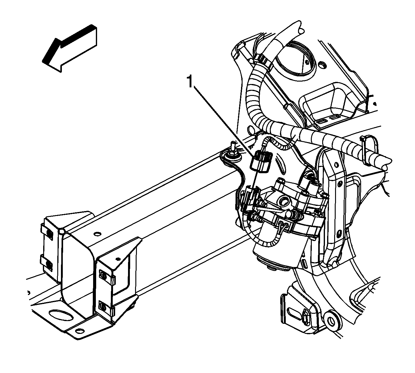
- Disconnect the engine wiring harness electrical connector (1) from the windshield wiper motor.
- Remove the engine harness clip (2) from the wiper motor hole.
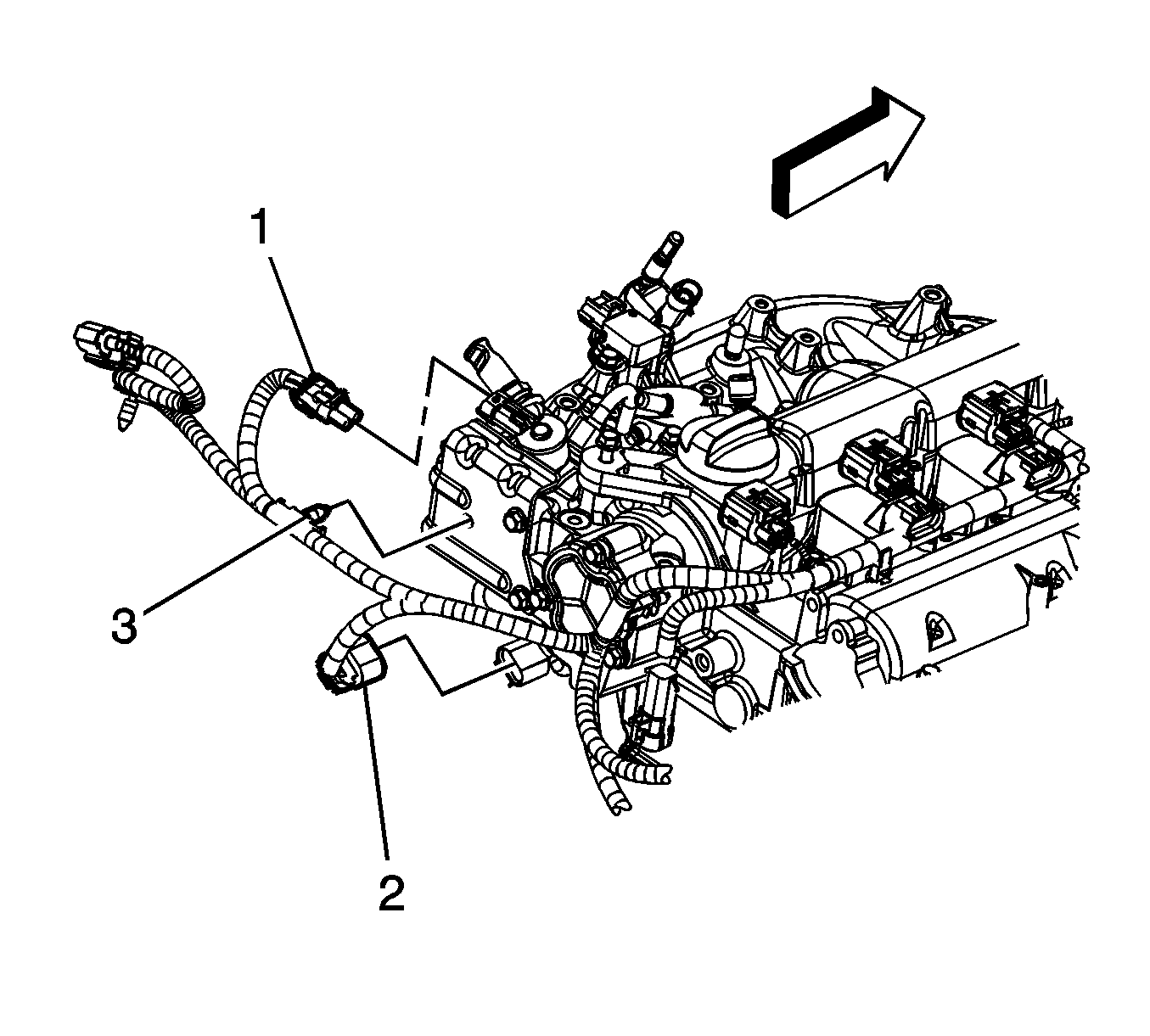
- Disconnect the engine wiring harness electrical connector (2) from the intake camshaft position (CMP) sensor.
- Disconnect the engine wiring harness electrical connector (1) from the high pressure fuel pump.
- Remove the engine wiring harness clip (3) from the high pressure fuel pump bracket.
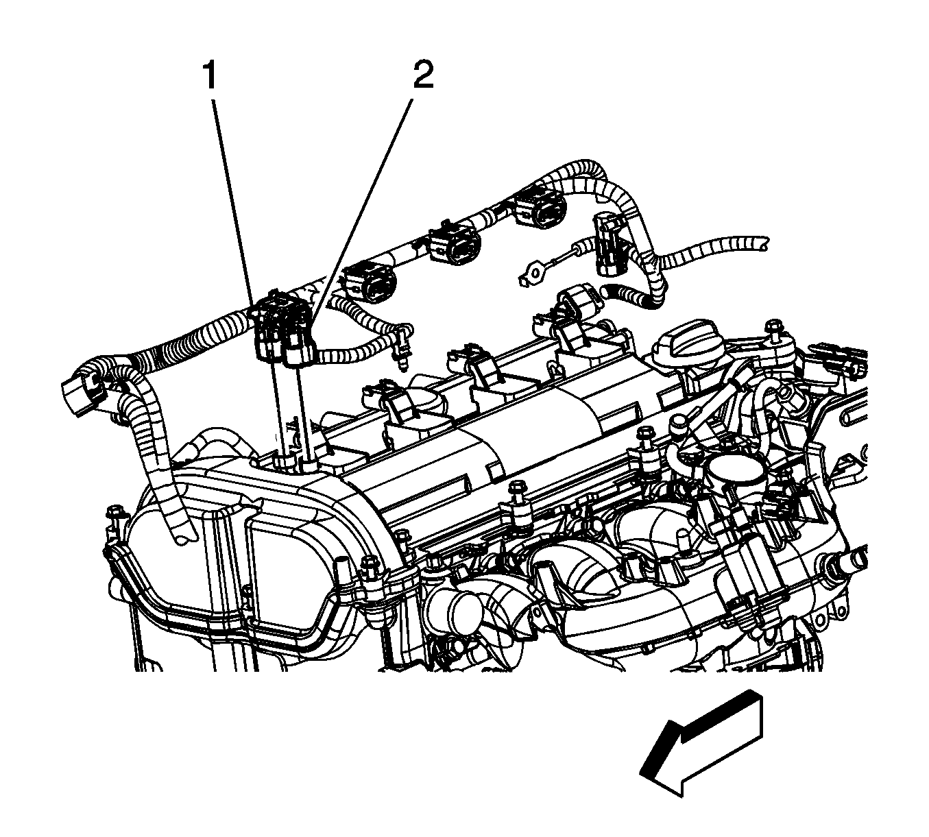
- Disconnect the engine wiring harness electrical connector (2) from the intake CMP actuator.
- Disconnect the engine wiring harness electrical connector (1) from the exhaust CMP actuator.
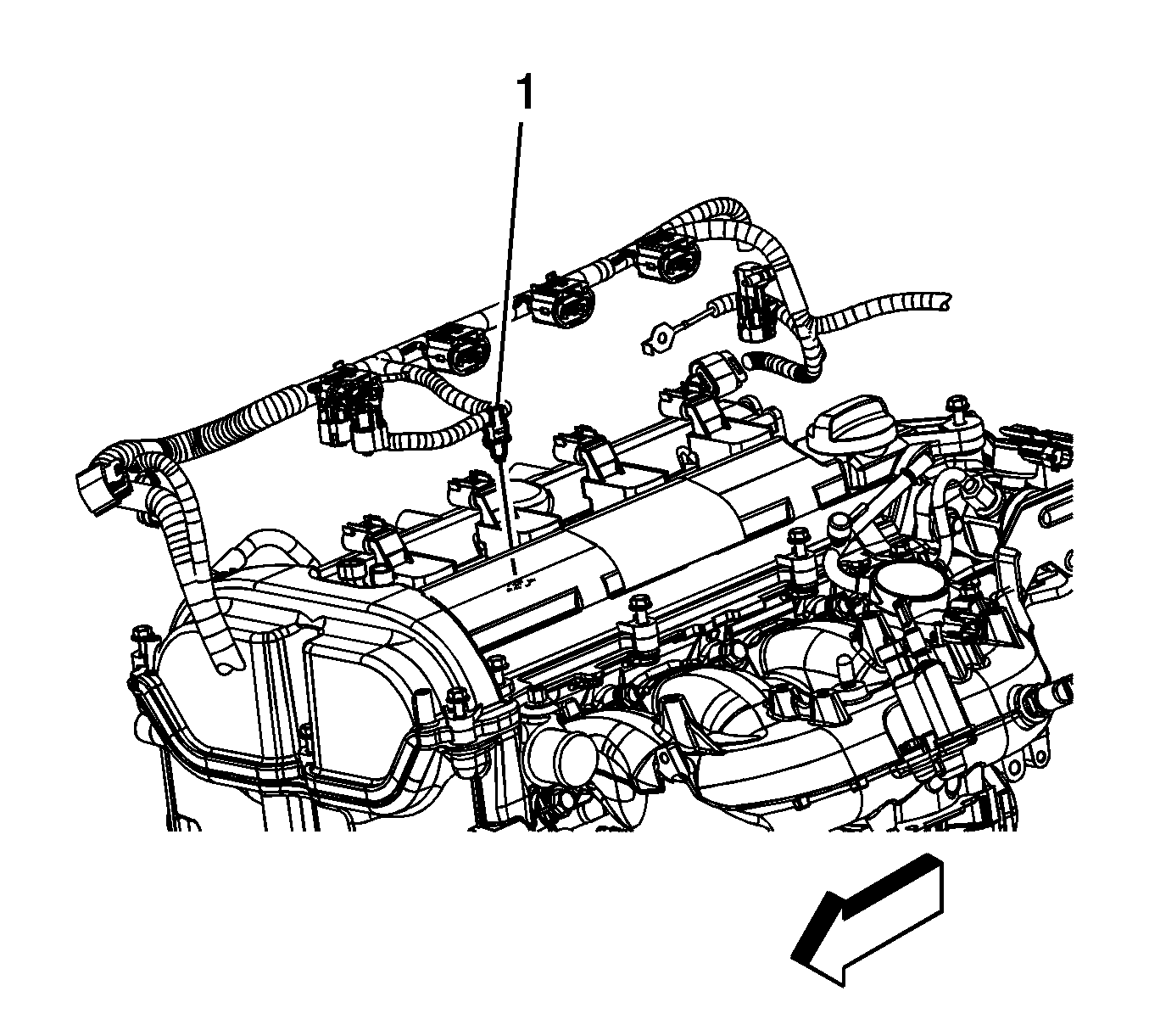
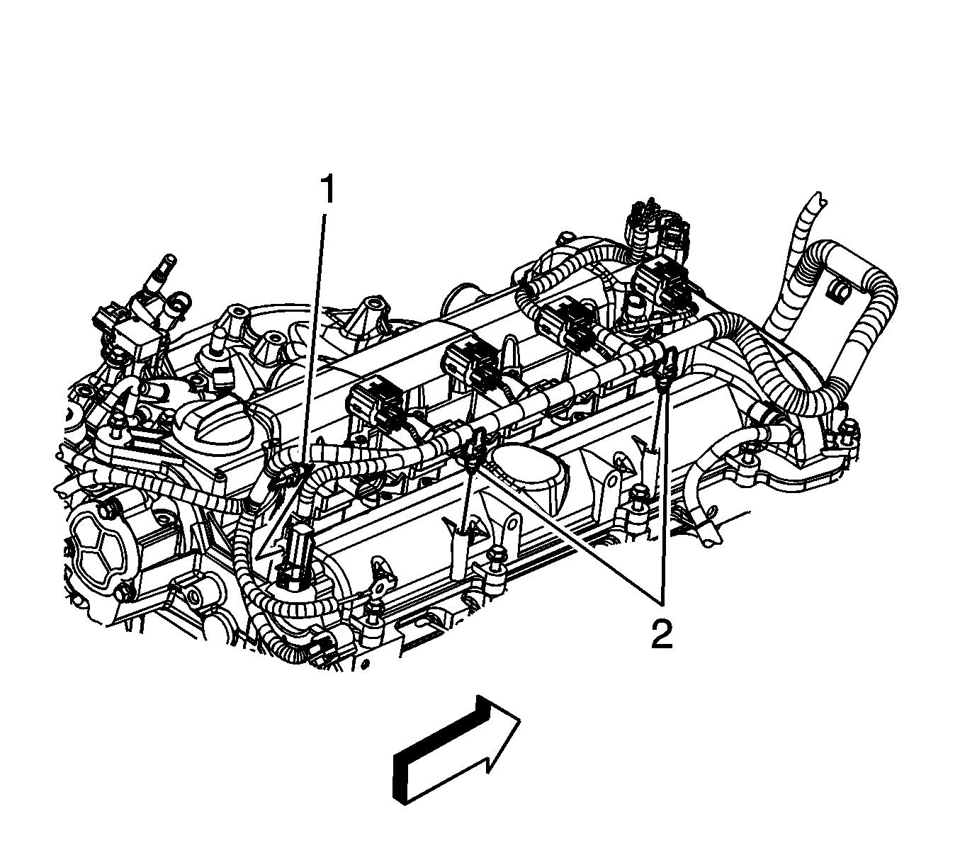
- Remove the engine harness clip (1) from the camshaft cover.
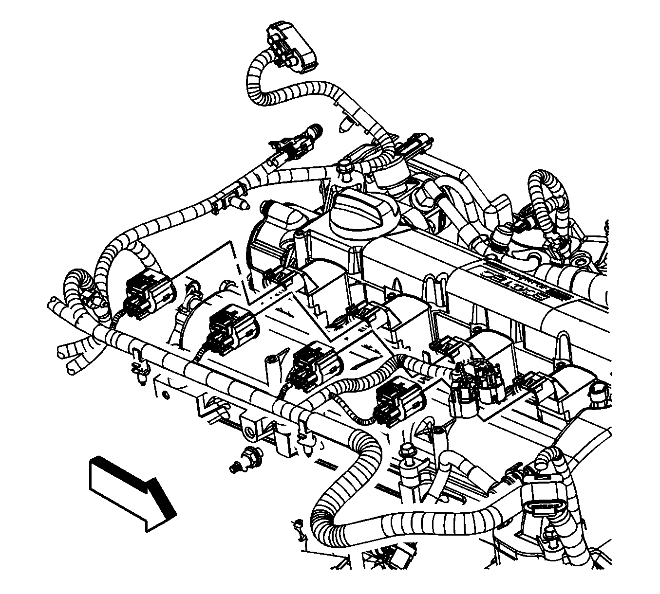
- Disconnect the engine wiring harness electrical connectors from the ignition coils.
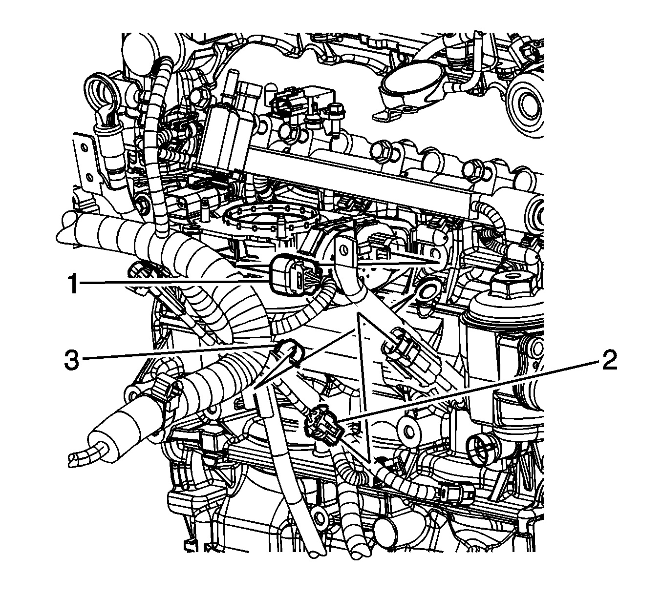
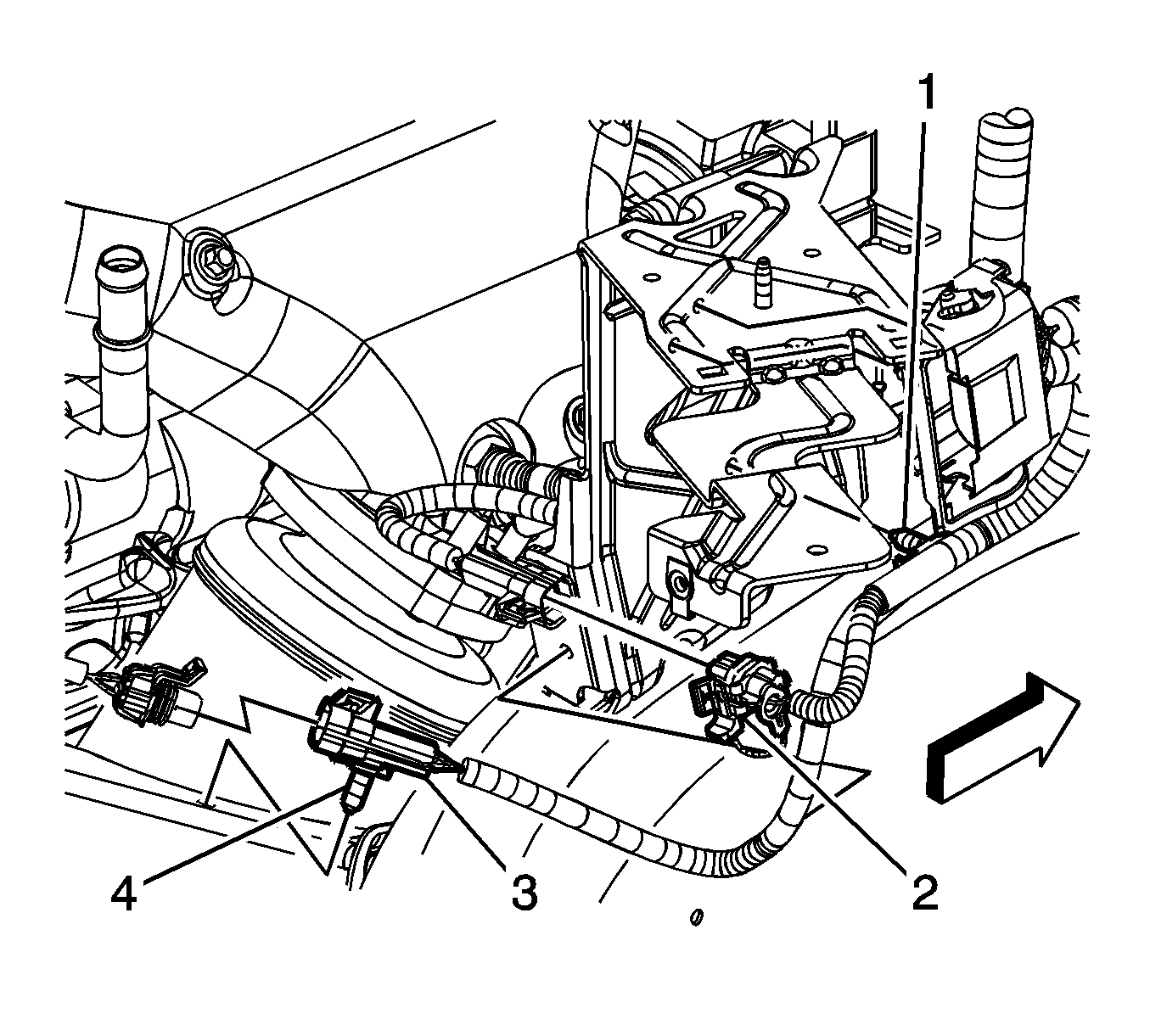
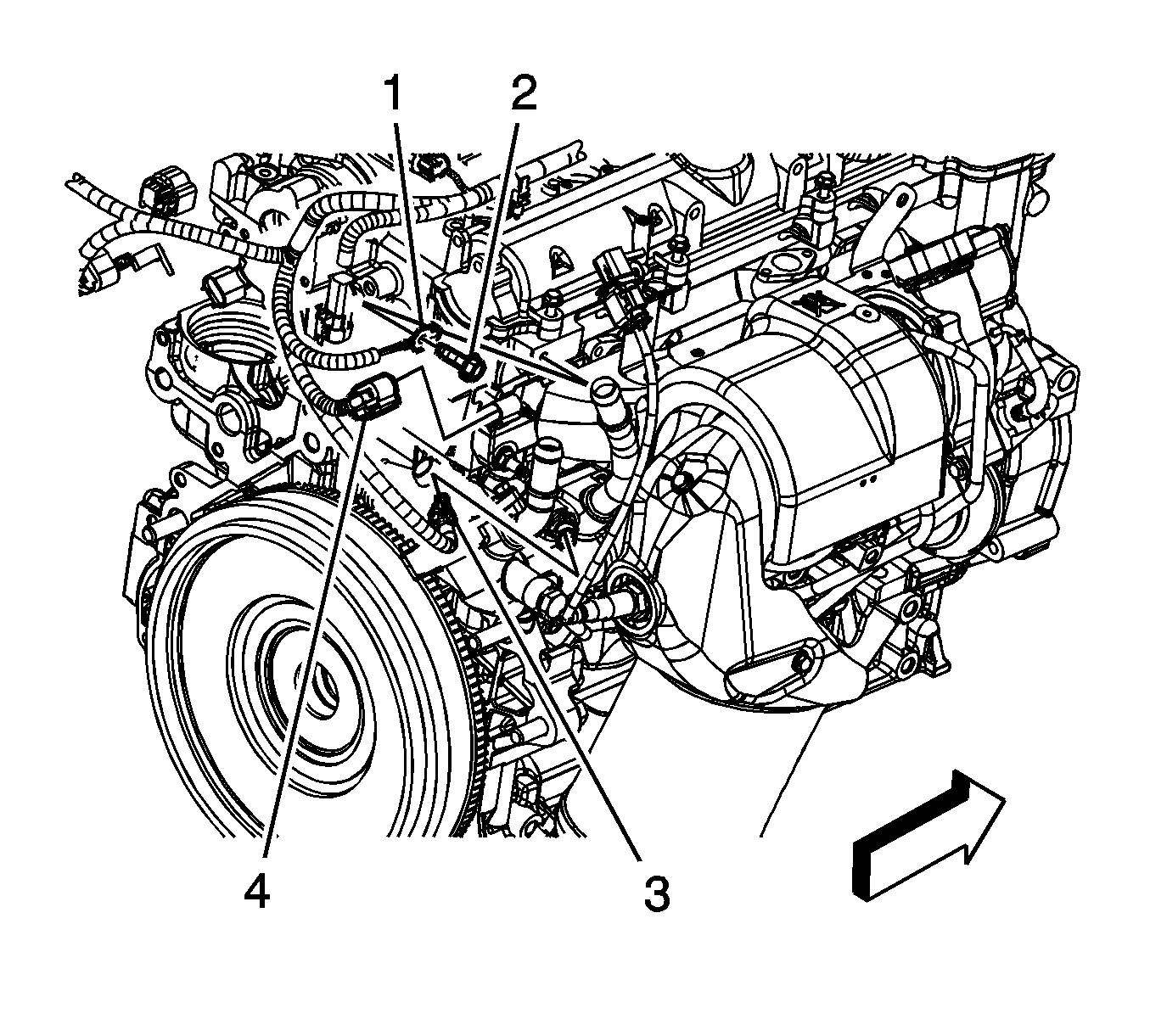
- Disconnect the engine wiring harness electrical connector (1) from the heated oxygen sensor (HO2S) (3).
- Disconnect the engine wiring harness electrical connector (4) from the exhaust CMP sensor.
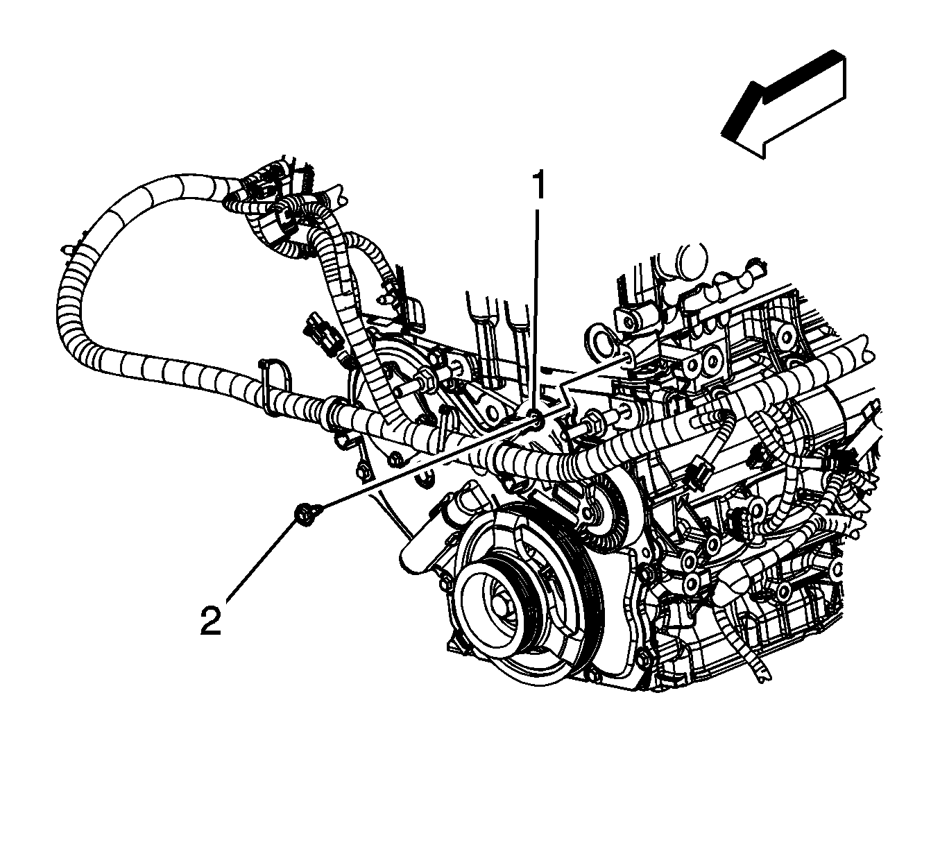
- Remove the engine harness ground terminal bolt (2) and reposition the engine harness ground terminal (1).
- Disconnect the engine wiring harness electrical connector (3) from the engine coolant temperature (ECT) sensor.
- Disconnect the engine harness clips (2) from the camshaft cover.
- Disconnect the engine harness clip (1) from the camshaft cover.
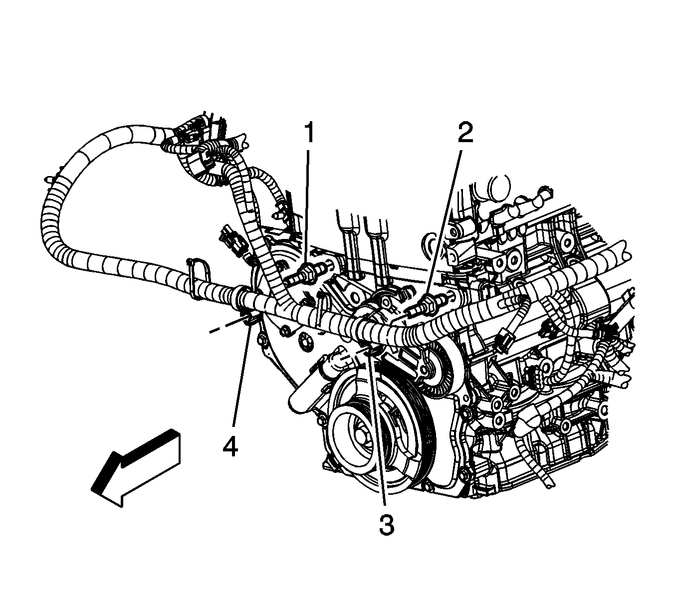
- Remove the engine wiring harness clip (3) from the turbocharger coolant feed pipe stud (2).
- Remove the engine wiring harness clip (1) from the turbocharger coolant feed pipe tab.
- Disconnect the engine wiring harness electrical connector from the boost sensor.
- Remove the engine wiring harness ground bolt (2) from the cylinder head.
- Remove the engine wiring harness ground terminal (1) from the cylinder head.
- Remove the engine harness clips (3, 4) from the front studs.
- Gather all branches of the engine harness and lay off to the side.
- Reposition the charge air bypass valve vacuum hose clamp (5) at the turbocharger.
- Remove the vacuum hose from the turbocharger coolant feed pipe clips (4).
- Remove the charge air bypass valve solenoid.
- Remove the turbocharger coolant feed pipe bolt (1) at the turbocharger.
- Remove the turbocharger coolant feed pipe fitting (2) from the cylinder head.
- Remove the turbocharger coolant feed pipe bracket bolt from the cylinder head.
- Remove the turbocharger coolant feed pipe bracket from the vehicle.
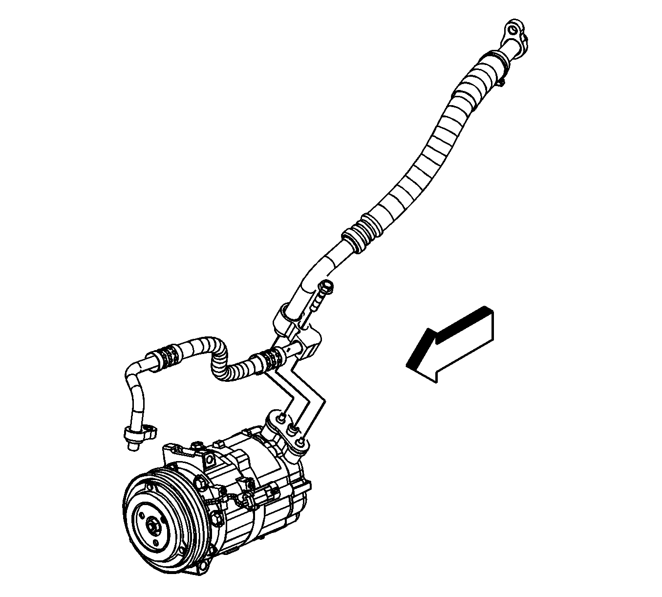
- Remove the A/C compressor line bolt and reposition the line off to the side.
- Raise and support the vehicle.
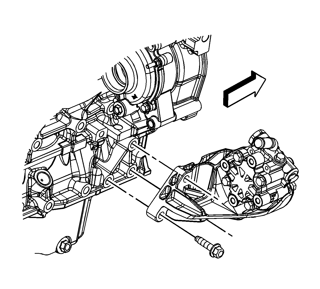
- Remove the power steering pump bracket bolts and reposition the pump and bracket off to the side.
- Remove the torque converter to flywheel bolts.
- Remove the 4 lower bellhousing bolts (2).
- Lower the vehicle.
- Remove the remaining upper 5 bellhousing bolts (1).
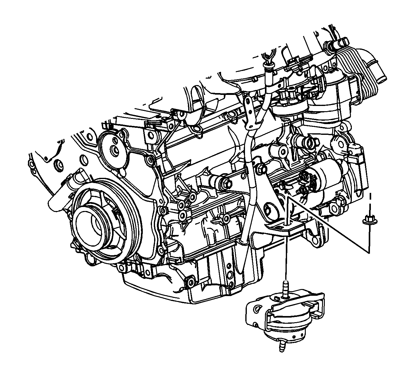
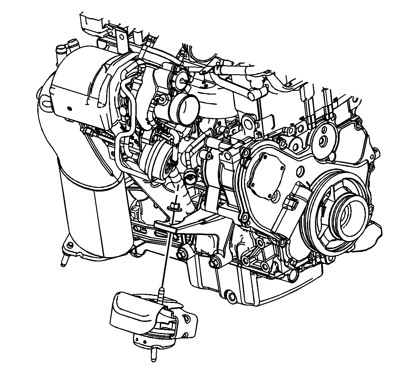
- Remove the left engine mount upper nut.
- Remove the right engine mount upper nut.
- If not present, install a service part engine lift bracket.
- Install a suitable engine lifting devise to the engine.
- Separate the engine from the transmission.
- Remove the engine from the vehicle.
- Remove the flywheel bolts and flywheel.
- Install the engine to an engine stand.
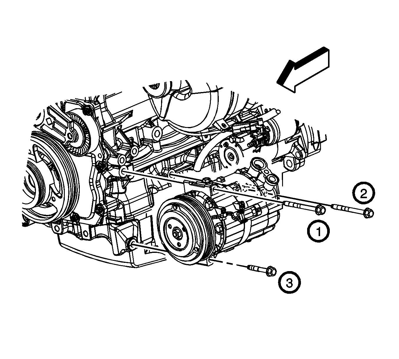
- Remove the A/C compressor bolts and compressor.
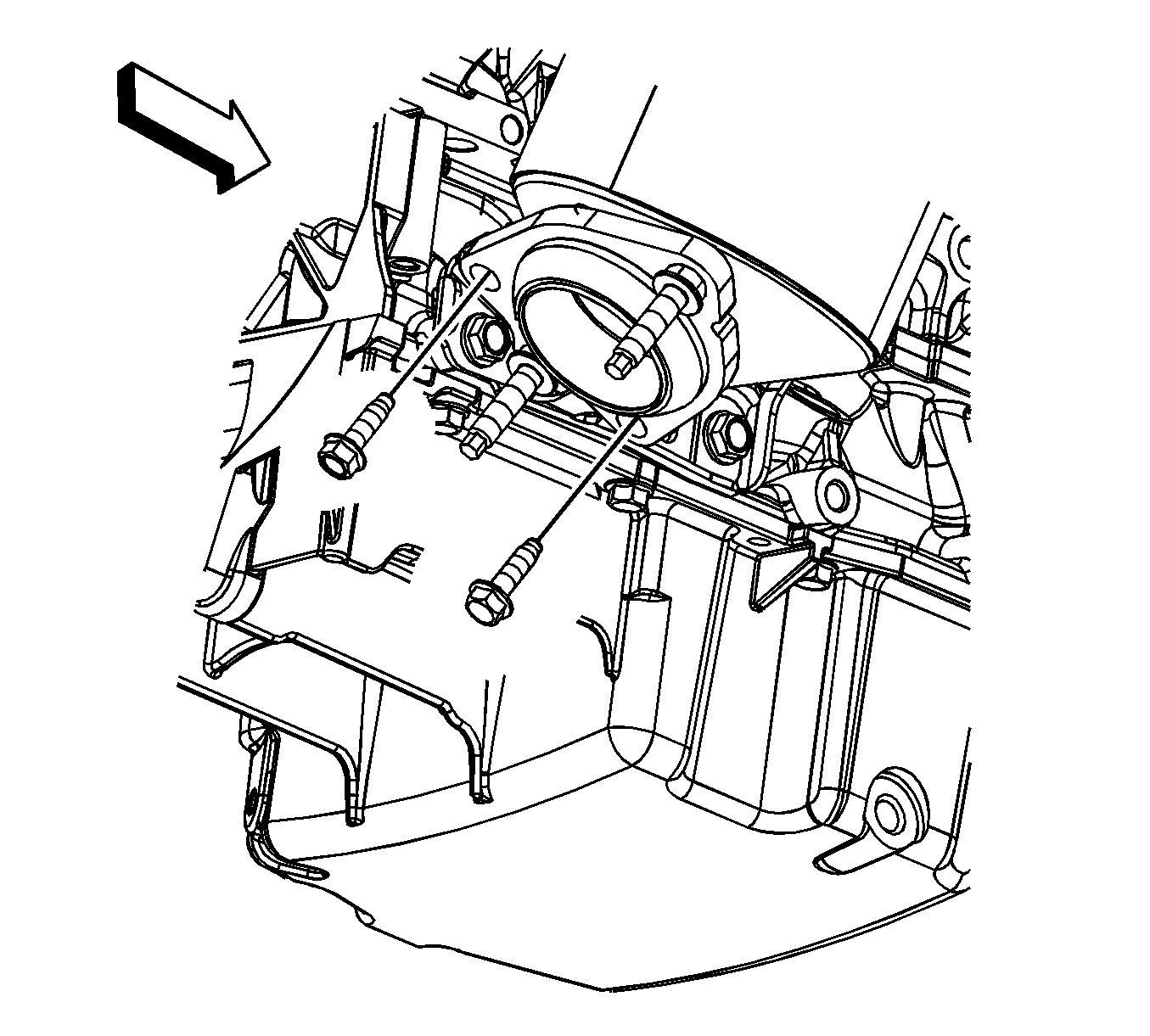
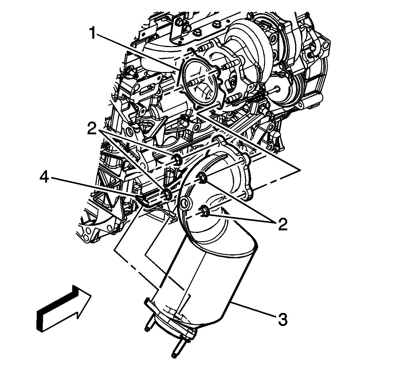
- Remove the catalytic converter to bracket bolts.
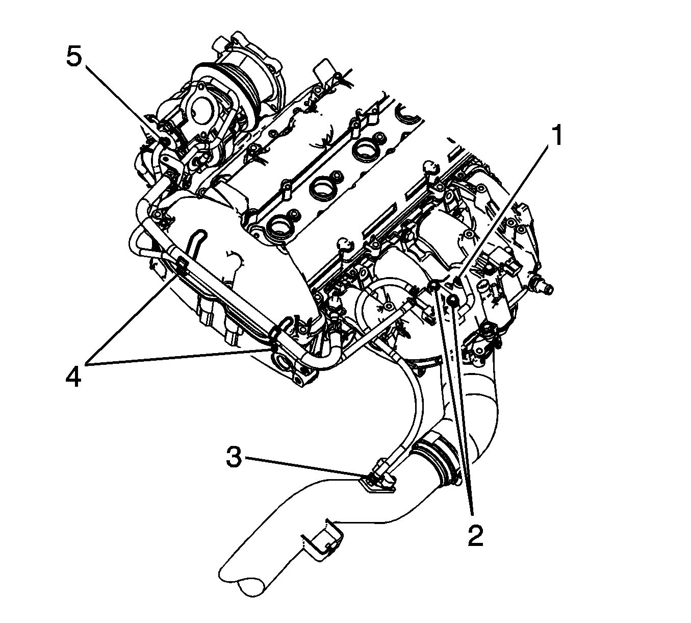
- Remove the catalytic converter nuts (2).
- Remove the catalytic converter (3) and gasket (1) from the turbocharger and bracket (4).
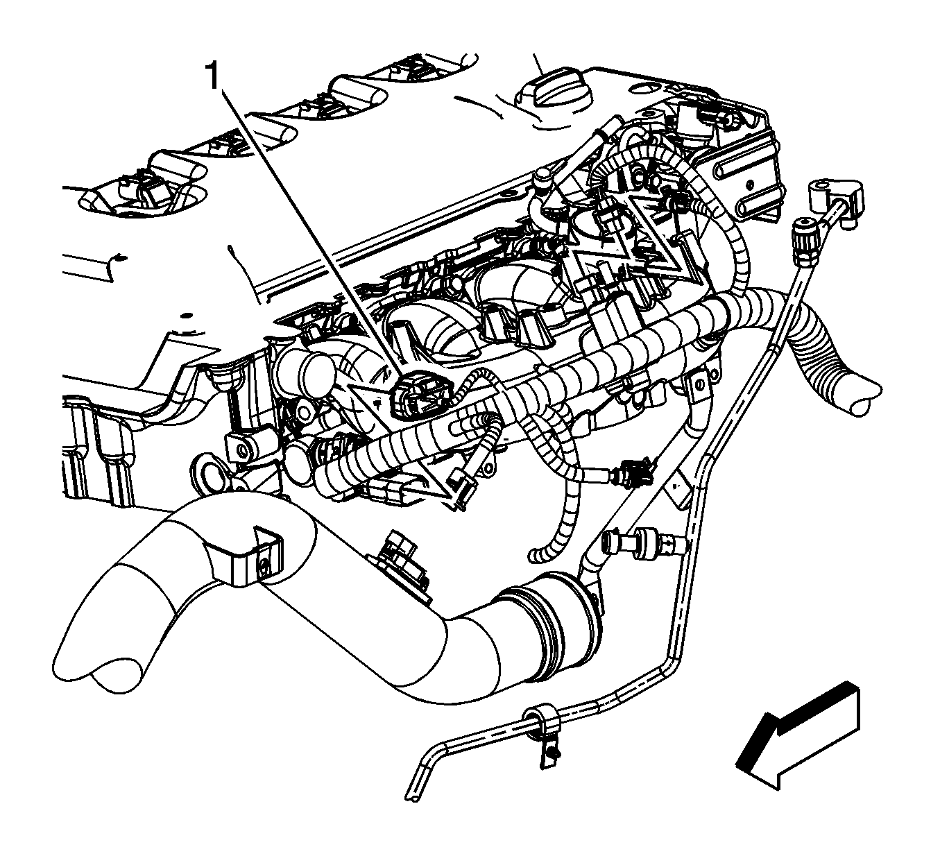

Important: The top 2 bellhousing bolts install through the bellhousing into the engine block. The remaining 7 bolts install through the engine block into the bellhousing.
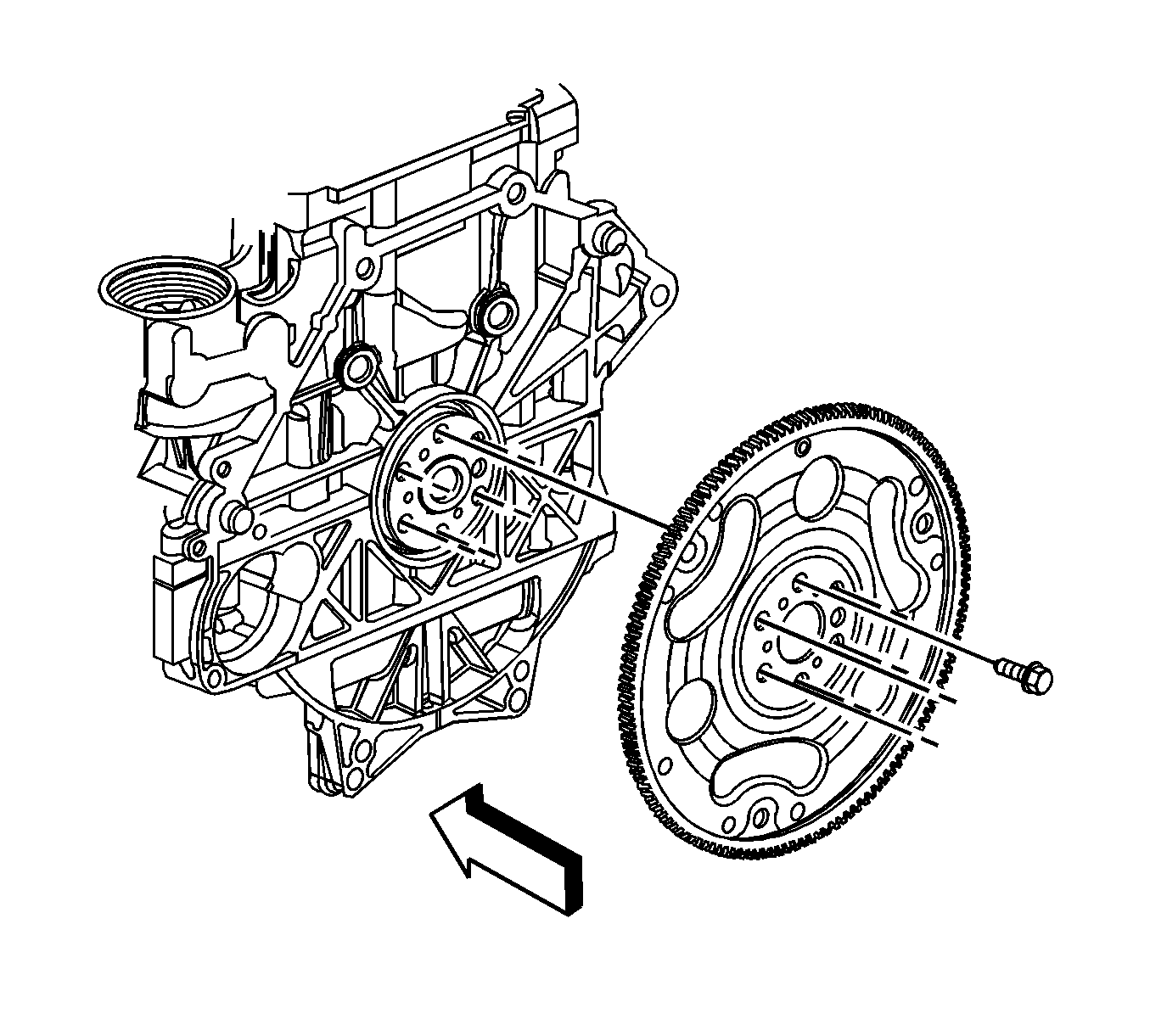
Important: It may be necessary to remove the chamfer (bevel) from the edge of an 18 mm socket in order to get full engagement on the thin headed flywheel bolts.
Installation Procedure
- Install the catalytic converter (3) and gasket (1) to the turbocharger and bracket (4).
- Install the catalytic converter nuts (2).
- Install the catalytic converter to bracket bolts.
- Install the A/C compressor and bolts.
- Install a suitable engine lifting devise to the engine.
- Remove the engine from the stand.
- Using a nylon bristle brush clean the thread adhesive from the flywheel bolt holes, if necessary.
- Install the flywheel and bolts.
- Install the engine to the vehicle.
- Install the right engine mount upper nut.
- Install the left engine mount upper nut.
- If installed, remove the engine lift bracket from the engine.
- Install the upper 5 bellhousing bolts (1).
- Raise and support the vehicle.
- Install the 4 lower bellhousing bolts (2).
- Install the torque converter to flywheel bolts.
- Position the power steering pump bracket to the engine and install the bracket bolts.
- Lower the vehicle.
- Position the A/C compressor line and install the bolt.
- Position the turbocharger coolant feed pipe to the vehicle.
- Install the turbocharger coolant feed pipe bracket bolt (3) to the cylinder head.
- Install the turbocharger coolant feed pipe fitting (2) to the cylinder head.
- Install the turbocharger coolant feed pipe bolt (1) at the turbocharger.
- Install the charge air bypass valve vacuum solenoid.
- Install the charge air bypass valve vacuum hose to the turbocharger coolant feed pipe clips (4).
- Position the charge air bypass valve vacuum hose clamp (5) at the turbocharger.
- Place the charge air bypass valve solenoid out of the way.
- Position the branches of the engine harness to the engine.
- Install the engine harness clips (3, 4) to the front studs.
- Install the engine wiring harness ground terminal (1) to the cylinder head.
- Install the engine wiring harness ground bolt (2) to the cylinder head.
- Connect the engine wiring harness electrical connector to the boost sensor.
- Install the engine wiring harness clip (1) to the turbocharger coolant feed pipe tab.
- Install the engine wiring harness clip (3) to the turbocharger coolant feed pipe stud (2).
- Connect the engine harness clips (2) to the camshaft cover.
- Connect the engine harness clip (1) to the camshaft cover.
- Connect the engine wiring harness electrical connector (4) to the exhaust CMP sensor.
- Connect the engine wiring harness electrical connector (3) to the ECT sensor.
- Position the engine harness ground terminal (1) and install the engine harness ground terminal bolt (2).
- Connect the engine wiring harness electrical connector (1) to the HO2S (3).
- Connect the engine wiring harness electrical connectors to the ignition coils.
- Install the engine harness clip (1) to the camshaft cover.
- Connect the engine wiring harness electrical connector (2) to the intake CMP actuator.
- Connect the engine wiring harness electrical connector (1) to the exhaust CMP actuator.
- Connect the engine wiring harness electrical connector (2) to the intake CMP sensor.
- Connect the engine wiring harness electrical connector (1) to the high pressure fuel pump.
- Install the engine wiring harness clip (3) to the high pressure fuel pump bracket.
- Connect the engine wiring harness electrical connector (1) to the windshield wiper motor.
- Install the engine harness clip (2) to the wiper motor hole.
- Connect the engine wiring harness electrical connector (1) to the brake booster vacuum sensor.
- Connect the engine wiring harness electrical connector (1) to the A/C refrigerant pressure sensor.
- Connect the engine wiring harness electrical connector (2) to the knock sensor.
- Connect the engine wiring harness electrical connector (1) to the fuel injector jumper electrical connector.
- Install the positive battery cable terminal (3) to the generator.
- Install the generator terminal nut (1).
- Position the positive battery cable terminal boot (2).
- Connect the engine wiring harness electrical connector (4) to the A/C compressor.
- Connect the engine wiring harness electrical connector (1) to the generator.
- Connect the engine wiring harness electrical connector (1) to the transmission oil cooler pump.
- Position the negative/positive battery cable to the engine.
- Install the negative battery cable ground terminal (5) to the engine lift bracket.
- Install the negative battery cable ground bolt (6) to the front engine lift bracket.
- Install NEW tie straps (1) to the engine wiring harness.
- Connect the engine wiring harness electrical connector (1) to the MAF sensor.
- Raise the vehicle.
- Connect the engine wiring harness electrical connector (1) to the brake booster vacuum pump.
- Bolt the catalytic converter to the exhaust pipe.
- Connect the engine wiring harness electrical connector (1) to the CKP sensor.
- Connect the engine wiring harness electrical connector (2) to the oil pressure sensor.
- Lower the vehicle.
- Install the heater inlet (1) and outlet (2) hoses to the thermostat housing.
- Position the heater inlet and outlet hose clamps at the thermostat housing.
- Position the air bleed hose to the engine.
- Install the surge tank air bleed hose to the engine.
- Install the surge tank air bleed hose clip (3) to the surge tank bracket.
- Position the surge tank air bleed hose clamp (1) at the engine.
- Install the surge tank clip (1) to the oil level indicator tube bracket.
- Position the surge tank outlet hose clamp (2) at the surge tank.
- Install the surge tank outlet hose to the thermostat housing and oil cooler.
- Position the surge tank outlet hose clamp (1) at the oil cooler.
- Position the surge tank outlet hose clamp (2) at the thermostat housing.
- Position the outlet hose to the engine.
- Install the radiator outlet hose clip (3) to the bracket.
- Install the radiator outlet hose to the thermostat housing and oil cooler.
- Position the radiator outlet hose clamp (1) at the oil cooler.
- Position the radiator outlet hose clamp (2) at the thermostat housing.
- Position the inlet hose to the engine.
- Install the radiator inlet hose to the engine.
- Position the radiator inlet hose clamp at the engine.
- Remove the cap or plug from the turbocharger opening.
- Install the charge air cooler pipe to the turbocharger.
- Install the charge air cooler pipe to turbocharger bolts (1).
- Install the turbocharger heat shield and bolts (1).
- Install the starter. Refer to Starter Motor Replacement .
- Install the air inlet grille panel. Refer to Air Inlet Grille Panel Replacement .
- Install the charge air cooler inlet and outlet pipes. Refer to Charge Air Cooler Inlet Pipe Replacement and Charge Air Cooler Outlet Pipe Replacement .
- Connect the fuel feed pipe (1) to the fuel line. Refer to Metal Collar Quick Connect Fitting Service .
- Connect the EVAP canister purge solenoid tube to the valve (2). Refer to Plastic Collar Quick Connect Fitting Service .
- Install the radiator. Refer to Radiator Replacement .
- Install the drive belt. Refer to Drive Belt Replacement .
- Recharge the A/C system. Refer to Refrigerant Recovery and Recharging .
- Install the hood. Refer to Hood Replacement .
- Connect the negative battery cable. Refer to Battery Negative Cable Disconnection and Connection .
- Fill the engine with oil.

Notice: Refer to Fastener Notice in the Preface section.
Tighten
Tighten the nuts to 59 N·m (43 lb ft).

Tighten
Tighten the bolts to 22 N·m (16 lb ft).

Tighten
Tighten the bolts in the sequence shown to 22 N·m (16 lb ft).

Tighten
Tighten the bolts to 53 N·m (39 lb ft) plus an additional 25 degrees using the
J 45059
.

Tighten
Tighten the nut to 55 N·m (41 lb ft).

Tighten
Tighten the nut to 55 N·m (41 lb ft).

Important: The top 2 bellhousing bolts install through the bellhousing into the engine block. The remaining 7 bolts install through the engine block into the bellhousing.
Tighten
Tighten the bolts to 50 N·m (37 lb ft).
Tighten
Tighten the bolts to 50 N·m (37 lb ft).
Tighten
Tighten the bolts to 63 N·m (46 lb ft).

Tighten
Tighten the bolts to 58 N·m (43 lb ft).

Tighten
Tighten the bolts to 22 N·m (16 lb ft).

Tighten
Tighten the bolt to 10 N·m (89 lb in).
Tighten
Tighten the fitting to 35 N·m (26 lb ft).
Tighten
Tighten the bolt to 35 N·m (26 lb ft).


Tighten
Tighten the bolt to 25 N·m (18 lb ft).


Tighten
Tighten the bolt to 25 N·m (18 lb ft).


Tighten
Tighten the nut to 20 N·m (15 lb ft).


Tighten
Tighten the bolt to 25 N·m (18 lb ft).


Tighten
Tighten the bolts to 17 N·m (13 lb ft).


Tighten
Tighten the bolts to 22 N·m (16 lb ft).

Tighten
Tighten the bolts to 10 N·m (89 lb in).

