For 1990-2009 cars only
Removal Procedure
- Open the hood.
- Remove the air cleaner outlet duct. Refer to Air Cleaner Outlet Duct Replacement.
- Raise the vehicle by its full height. Refer to Lifting and Jacking the Vehicle.
- Drain the cooling system. Refer to Cooling System Draining and Filling.
- Remove the 2 intake manifold brace bolts (2, 3).
- Remove and disconnect the wiring harness plug of the heated oxygen sensor 1.
- Remove the intake manifold brace (1).
- Lower the vehicle by its full height.
- Disconnect wiring harness plug.
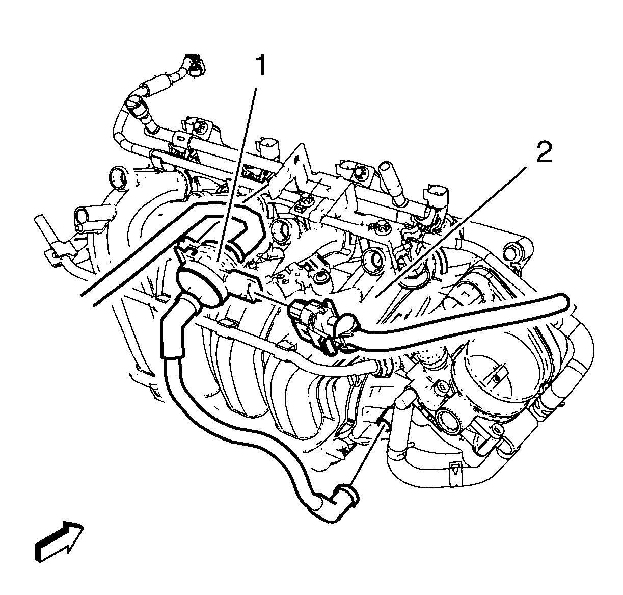
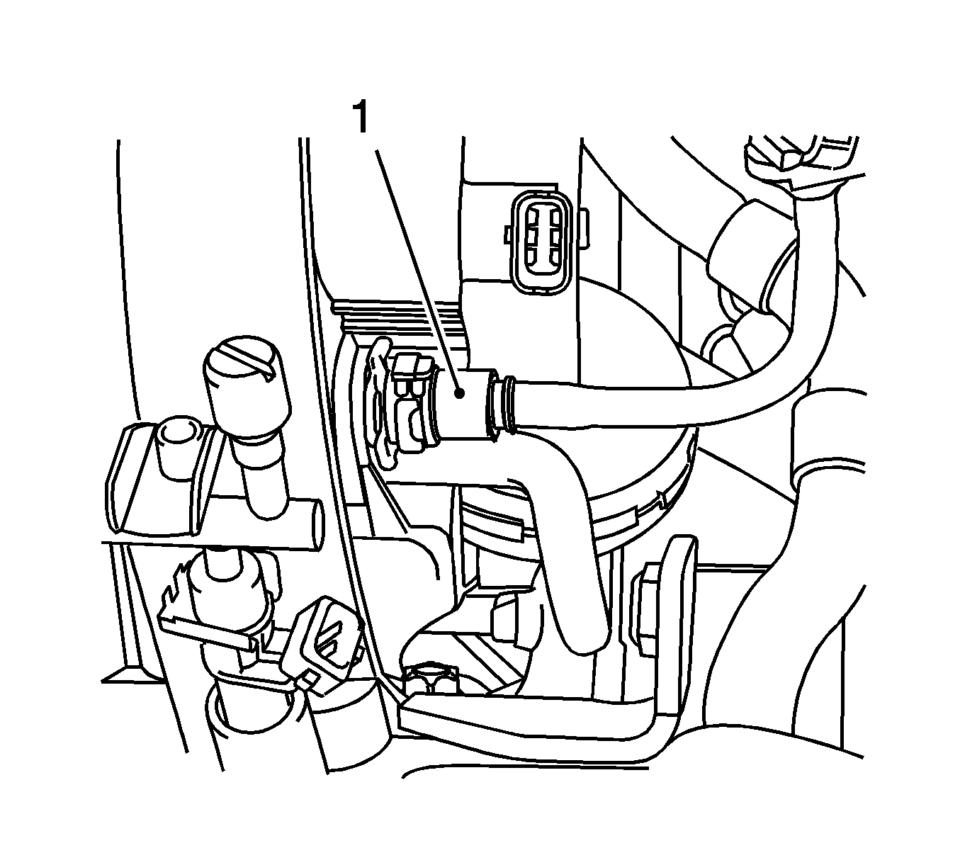
- Disconnect the pipes from the evaporative emission canister purge solenoid valve (1).
- Remove the evaporative emission canister purge solenoid valve (1) and the rubber mounting from the intake manifold (2).
- Remove the positive crankcase ventilation tube. Refer to Positive Crankcase Ventilation Hose/Pipe/Tube Replacement.
- Remove the throttle body assembly. Refer to Throttle Body Assembly Replacement.
- Disconnect the manifold absolute pressure sensor wiring harness plug. Refer to Manifold Absolute Pressure Sensor Replacement.
- Remove the engine management wiring harness and the fuel injectors wiring harness.
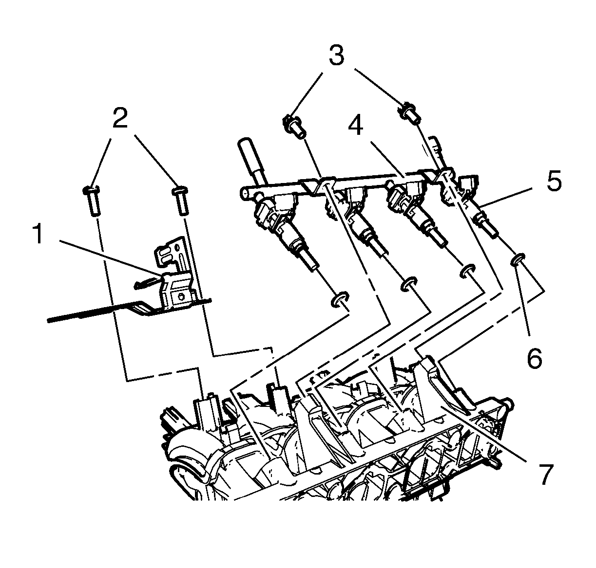
- Remove the 2 evaporative emission canister purge solenoid valve bracket bolts (2).
- Remove the evaporative emission canister purge solenoid valve bracket (1) from the intake manifold (7).
- Remove the 2 multiport fuel injection fuel rail bolts (3).
- Remove the multiport fuel injection fuel rail (4) and the fuel injectors (5) from the intake manifold (7).
- Remove the 4 multiport fuel injector seals (6).
- Remove the manifold absolute pressure sensor. Refer to Manifold Absolute Pressure Sensor Replacement.
- Disconnect the booster vacuum pipe (1) from the intake manifold.
- Remove the 7 intake manifold bolts (1).
- Remove the intake manifold (2).


Cleaning and Inspection Procedure
Clean and Inspect the intake manifold. Refer to Intake Manifold Cleaning and Inspection.
Installation Procedure
- Clean the sealing surfaces.
- Install the NEW gasket.
- Install the intake manifold (2) and the 7 intake manifold bolts (1) and tighten to 20 N·m (15 lb ft).
- Connect the booster vacuum pipe (1) to the intake manifold.
- Install the manifold absolute pressure sensor. Refer to Manifold Absolute Pressure Sensor Replacement.
- Install the 4 multiport fuel injector seals (6).
- Install the multiport fuel injection fuel rail (4) and the fuel injectors (5) to the intake manifold (7).
- Install the 2 multiport fuel injection fuel rail bolts and tighten to 8 N·m (71 lb in).
- Install the evaporative emission canister purge solenoid valve bracket (1) to the intake manifold (7).
- Install the 2 evaporative emission canister purge solenoid valve bracket bolts (2) and tighten to 8 N·m (71 lb in).
- Install the engine management wiring harness.
- Connect the manifold absolute pressure sensor wiring harness plug. Refer to Manifold Absolute Pressure Sensor Replacement.
- Install the throttle body assembly. Refer to Throttle Body Assembly Replacement.
- Install the positive crankcase ventilation tube. Refer to Positive Crankcase Ventilation Hose/Pipe/Tube Replacement.
- Install the evaporative emission canister purge solenoid valve (1) and the rubber mounting to the intake manifold (2).
- Connect the pipes to the evaporative emission canister purge solenoid valve (1).
- Connect wiring harness plug.
- Raise the vehicle by its full height.
- Install the intake manifold brace (1).
- Install and disconnect the wiring harness plug of the heated oxygen sensor 1.
- Install the 2 intake manifold brace bolts (2; 3) and tighten to 8 N·m (71 lb in).
- Lower the vehicle by its full height.
- Fill the cooling system. Refer to Cooling System Draining and Filling.
- Install the air cleaner outlet duct. Refer to Air Cleaner Outlet Duct Replacement.
- Close the hood.
Caution: Refer to Fastener Caution in the Preface section.


Caution: Refer to Fastener Caution in the Preface section.


