For 1990-2009 cars only
Special Tools
CH 49375 Wrench
For equivalent regional tools, refer to Special Tools.
Warning: Refer to Brake Fluid Irritant Warning in the Preface section.
Caution: Refer to Brake Fluid Effects on Paint and Electrical Components Caution in the Preface section.
Removal Procedure
Caution: Always connect or disconnect the wiring harness connector from the EBCM/EBTCM with the ignition switch in the OFF position. Failure to observe this precaution could result in damage to the EBCM/EBTCM.
- Raise and the vehicle. Refer to Lifting and Jacking the Vehicle.
- Remove the tire and wheel assembly. Refer to Tire and Wheel Removal and Installation.
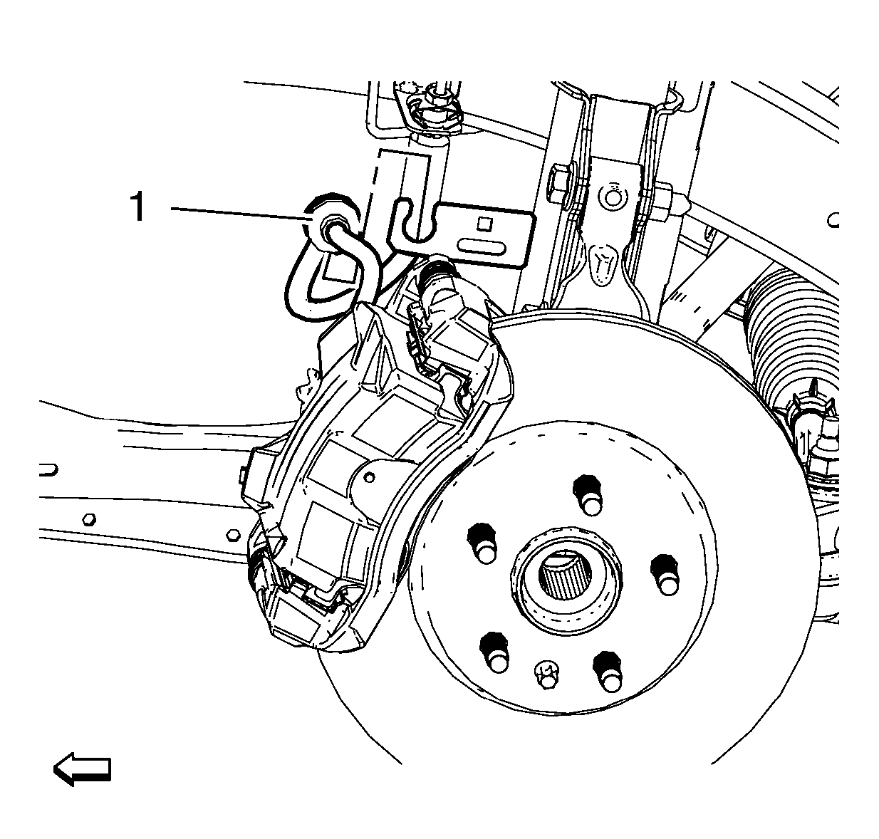
- Separate the brake hose (1) from the shock absorber.
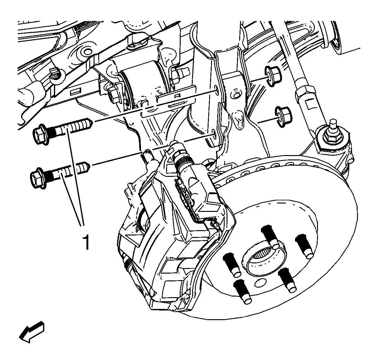
- Remove the steering knuckle nuts and bolts (1).
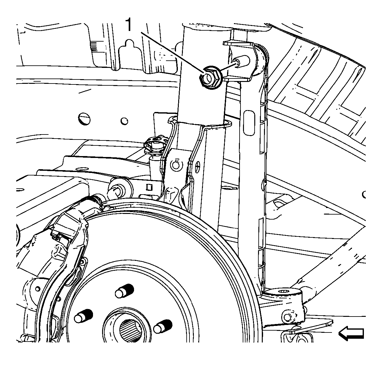
- Remove the stabilizer shaft link nut (1) from the front strut.
- Lower the vehicle.
- Open the hood.
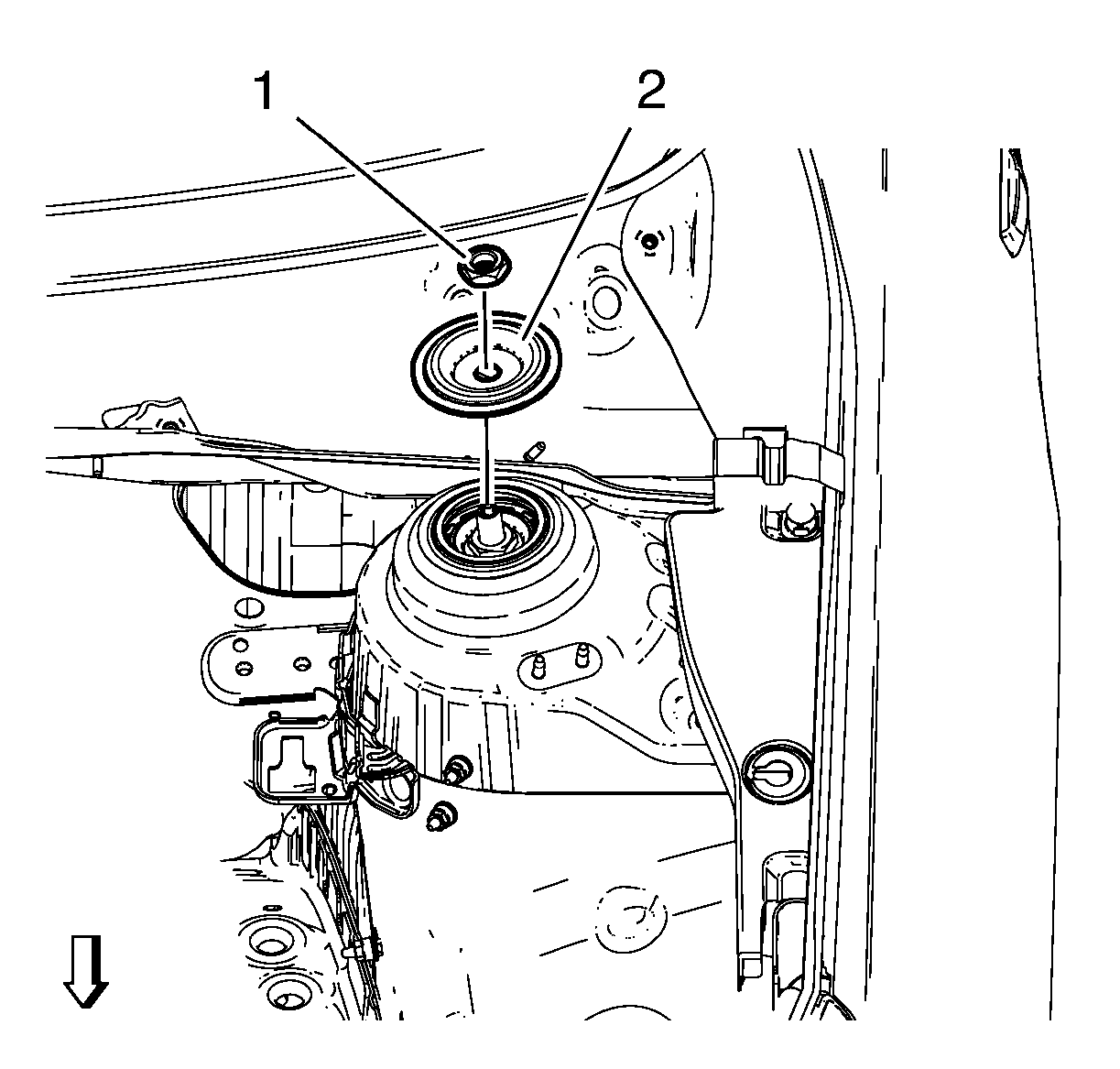
- Remove the upper strut mount nut (1), use the CH 49375 wrench .
- Remove the strut mounting plate (2).
- Separate the front strut from the knuckle.
- Remove the front strut assembly from the vehicle.
- For servicing the individual strut components, refer to Strut, Strut Component, and Spring Replacement.


Installation Procedure
- Install the front strut assembly.
- Install the strut mounting plate.
- Install the upper strut mount nut, using the CH 49375 wrench and tighten to 45 N·m (34 lb ft).
- Insert the front strut in the knuckle.
- Install the steering knuckle nuts and bolts (1) and tighten to 45 N·m (34 lb ft).
- Install the stabilizer shaft link nut (1) and tighten to 65 N·m (48 lb ft).
- Install the brake hose (1) to the strut.
- Install the front tire and wheel assembly. Refer to Tire and Wheel Removal and Installation.
- Lower the vehicle.
- Check the front end alignment specifications. Refer to Wheel Alignment Specifications.
Caution: Refer to Fastener Caution in the Preface section.


