For 1990-2009 cars only
Removal Procedure
Warning: Refer to Brake Fluid Irritant Warning in the Preface section.
Caution: Refer to Brake Fluid Effects on Paint and Electrical Components Caution in the Preface section.
- Disconnect the brake fluid level indicator switch electrical connector and separate from brake fluid reservoir.
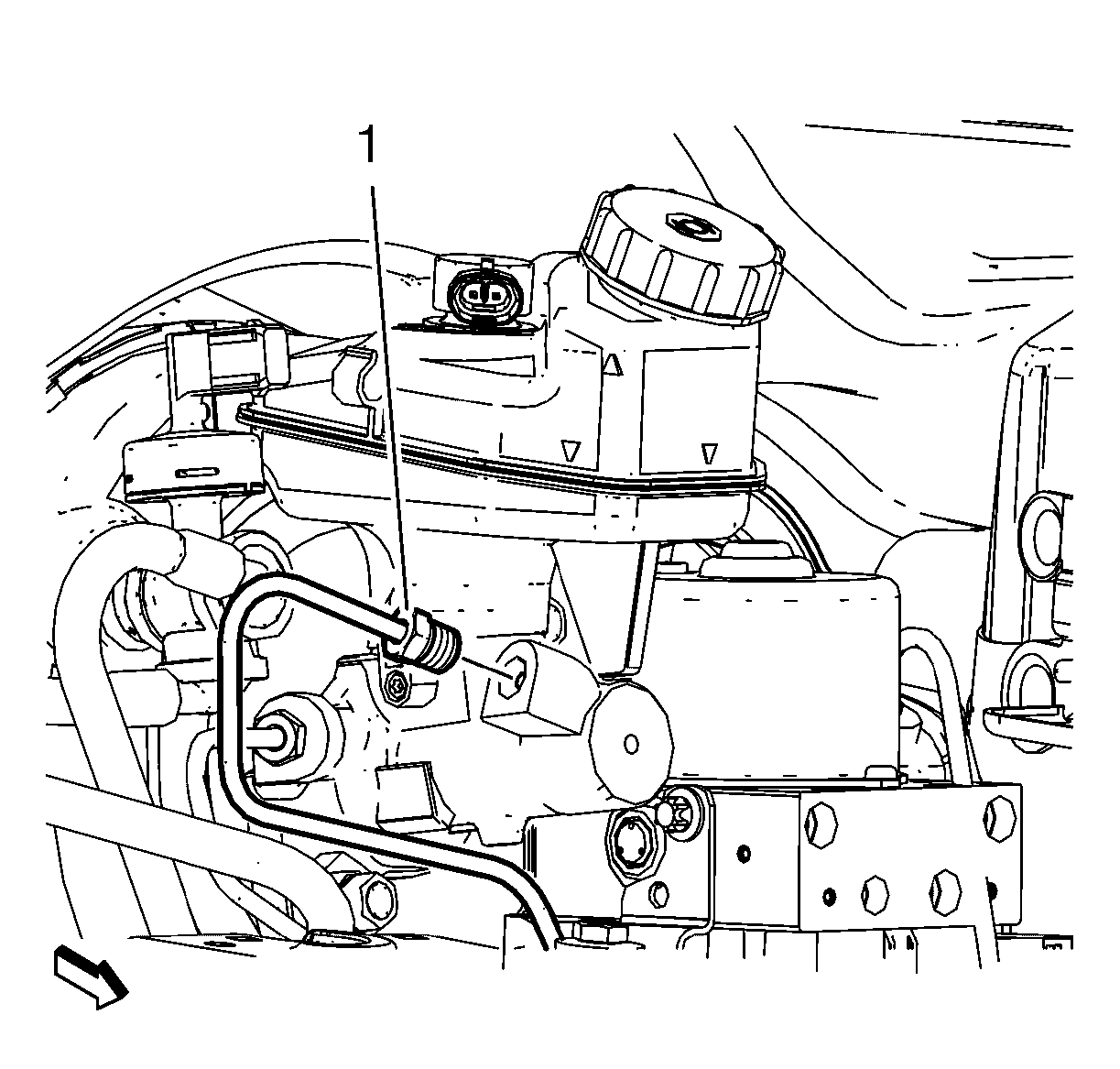
- Disconnect the master cylinder secondary brake pipe fitting (1).
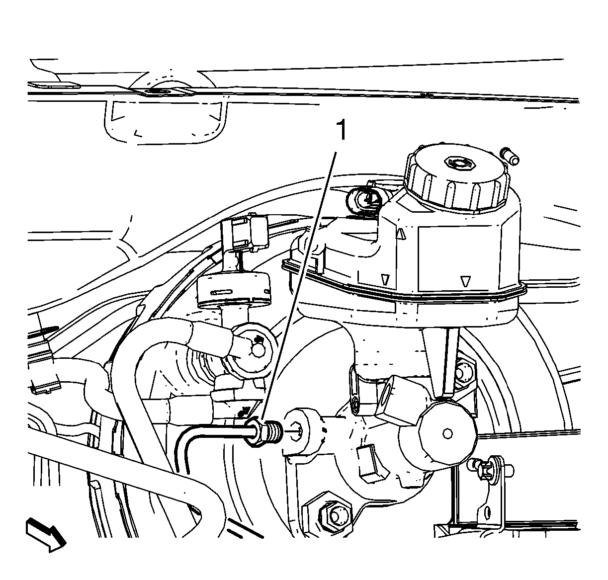
- Disconnect the master cylinder primary brake pipe fitting.
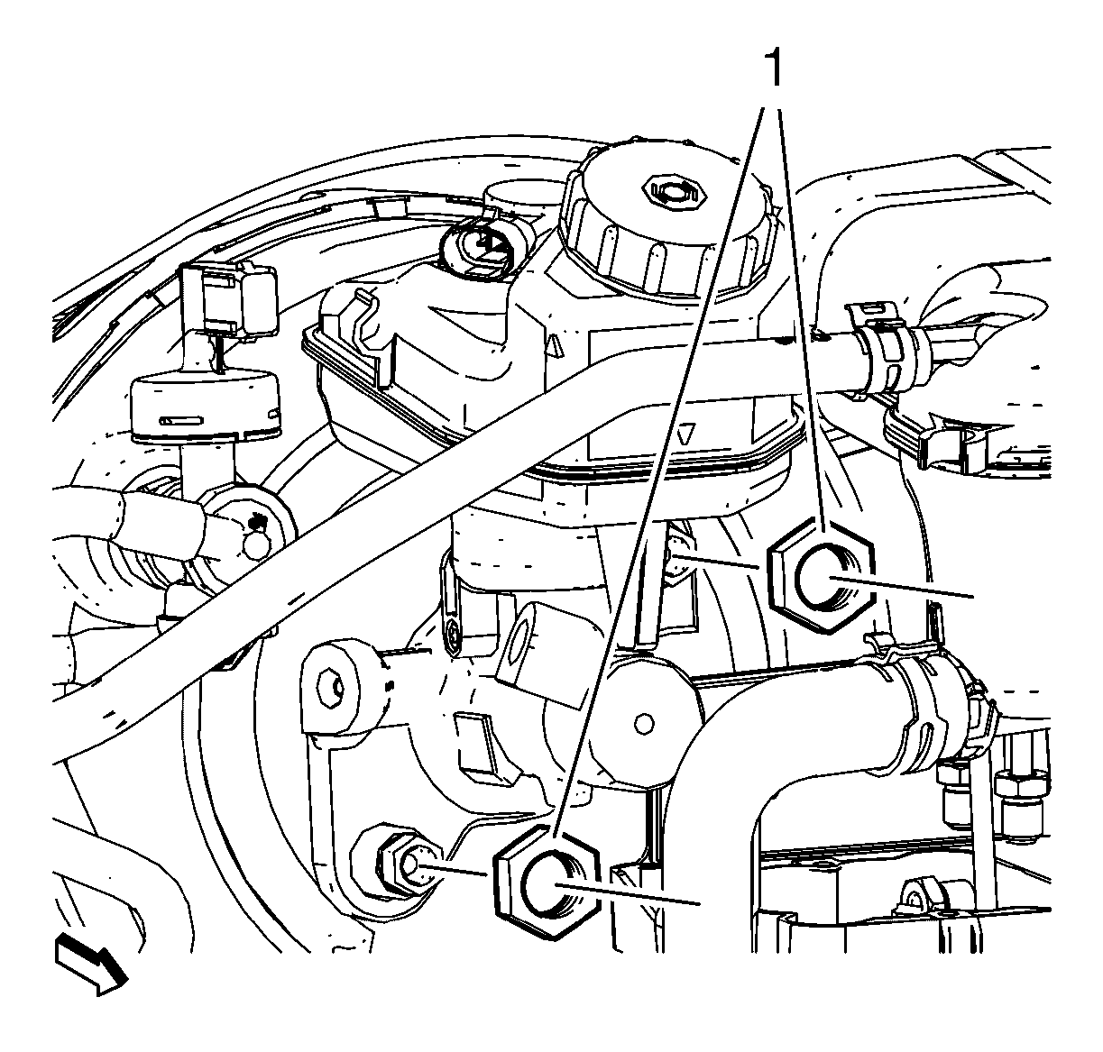
- Remove master cylinder nuts (1).
- Remove master cylinder with brake fluid reservoir.
- Inspect the master cylinder to vacuum brake booster seal for damage and replace, if necessary.
- Remove the master cylinder reservoir, if necessary. Refer to Master Cylinder Reservoir Replacement.

Cap the brake pipe fitting and plug the master cylinder outlet port to prevent brake fluid loss and contamination.

Cap the brake pipe fitting and plug the master cylinder outlet port to prevent brake fluid loss and contamination.

Installation Procedure
- Install the brake fluid reservoir to master cylinder. Refer to Master Cylinder Reservoir Replacement.
- Bench bleed the master cylinder. Refer to Master Cylinder Bench Bleeding.
- Ensure the master cylinder to vacuum brake booster seal is properly seated on the master cylinder barrel.
- Install master cylinder nuts (1) and tighten to 20 N·m (15 lb ft).
- Disconnect the brake fluid level indicator switch electrical connector and separate from brake fluid reservoir.
- Connect the master cylinder primary brake pipe fitting (1) and tighten to Xx N·m (xx lb ft).
- Connect the master cylinder primary brake pipe fitting and tighten to Xx N·m (xx lb ft).
- Connect the brake fluid level indicator switch electrical connector.
- Bleed the hydraulic brake system. Refer to Hydraulic Brake System Bleeding.
Caution: Refer to Fastener Caution in the Preface section.


