| Figure 1: |
X102 Body Front Harness & Engine Cooling Harness
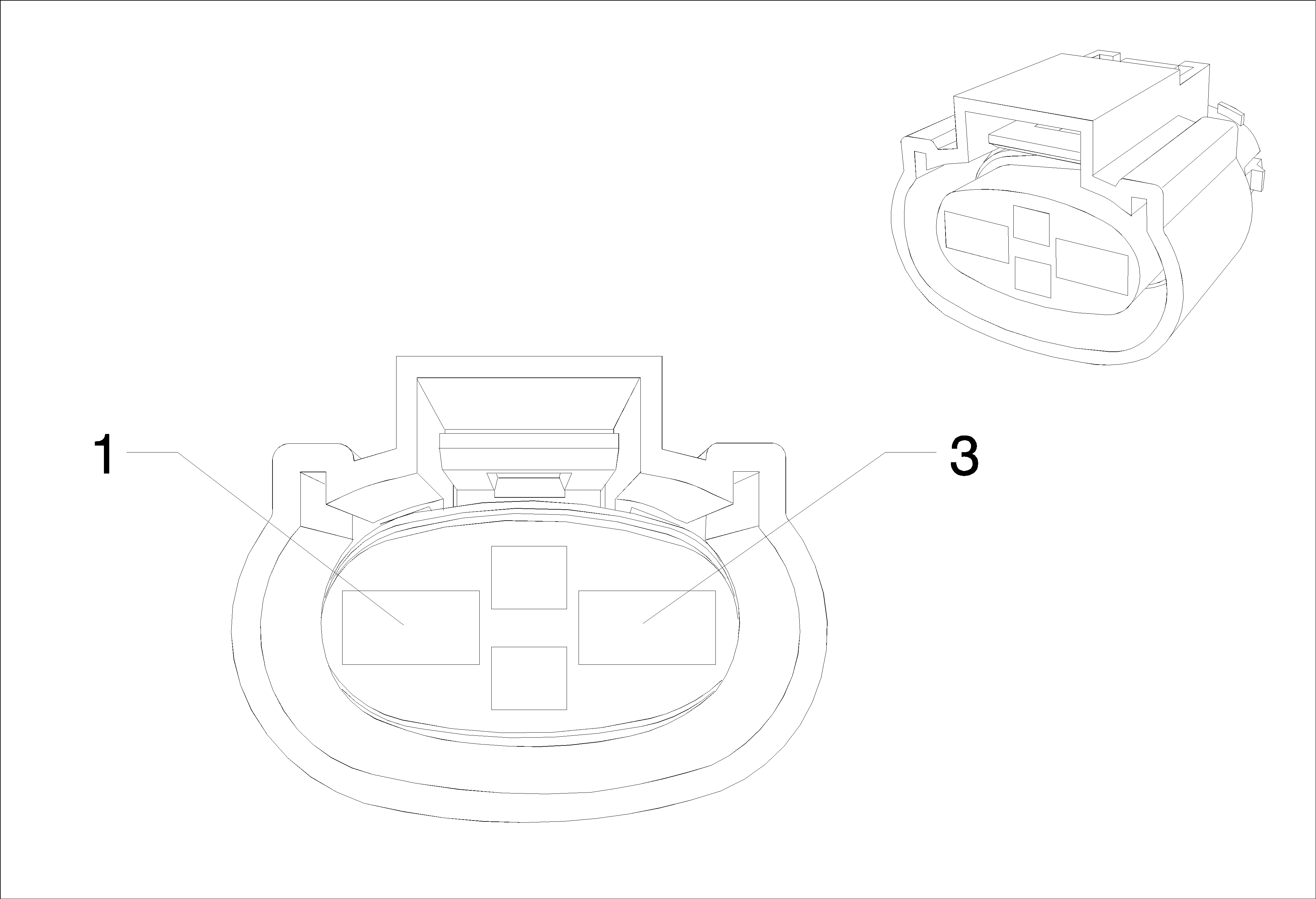
Connector Part Information
|
Terminal Part Information
|
Pin | Wire | Circuit | Function |
|---|---|---|---|
1 | 4 Yellow | 5358 | Cooling Fan Motor Control (3) (LLW) |
4 Yellow | 5358 | Cooling Fan Motor Control (3) (LXT) | |
4 Yellow | 5358 | Cooling Fan Motor Control (3) (D) | |
4 Yellow | 5358 | Cooling Fan Motor Control (3) (FI) | |
4 Yellow | 5358 | Cooling Fan Motor Control (3) (LXV LDE 2H0) | |
2 | 2.5 Gray | 532 | Cooling Fan Motor Control (2) (LLW) |
2.5 Gray | 532 | Cooling Fan Motor Control (2) (LXT) | |
2.5 Gray | 532 | Cooling Fan Motor Control (2) (D) | |
2.5 Gray | 532 | Cooling Fan Motor Control (2) (FI) | |
2.5 Gray | 532 | Cooling Fan Motor Control (2) (LXV LDE 2H0) | |
3 | 4 White-Black | 2366 | Cooling Fan Control Relay Speed Signal (LLW) |
2.5 White-Blue | 409 | Cooling Fan Motor Control (1) | |
2.5 White-Blue | 409 | Cooling Fan Motor Control (1) (LXV LDE 2H0) | |
2.5 White-Blue | 409 | Cooling Fan Motor Control (1) (LXT) | |
4 | 0.75 Brown-Green | 59 | A/C Compressor Clutch Control |
0.5 Brown-Green | 59 | A/C Compressor Clutch Control (LXT) |
X104 Body Front Harness & Engine Cooling Harness
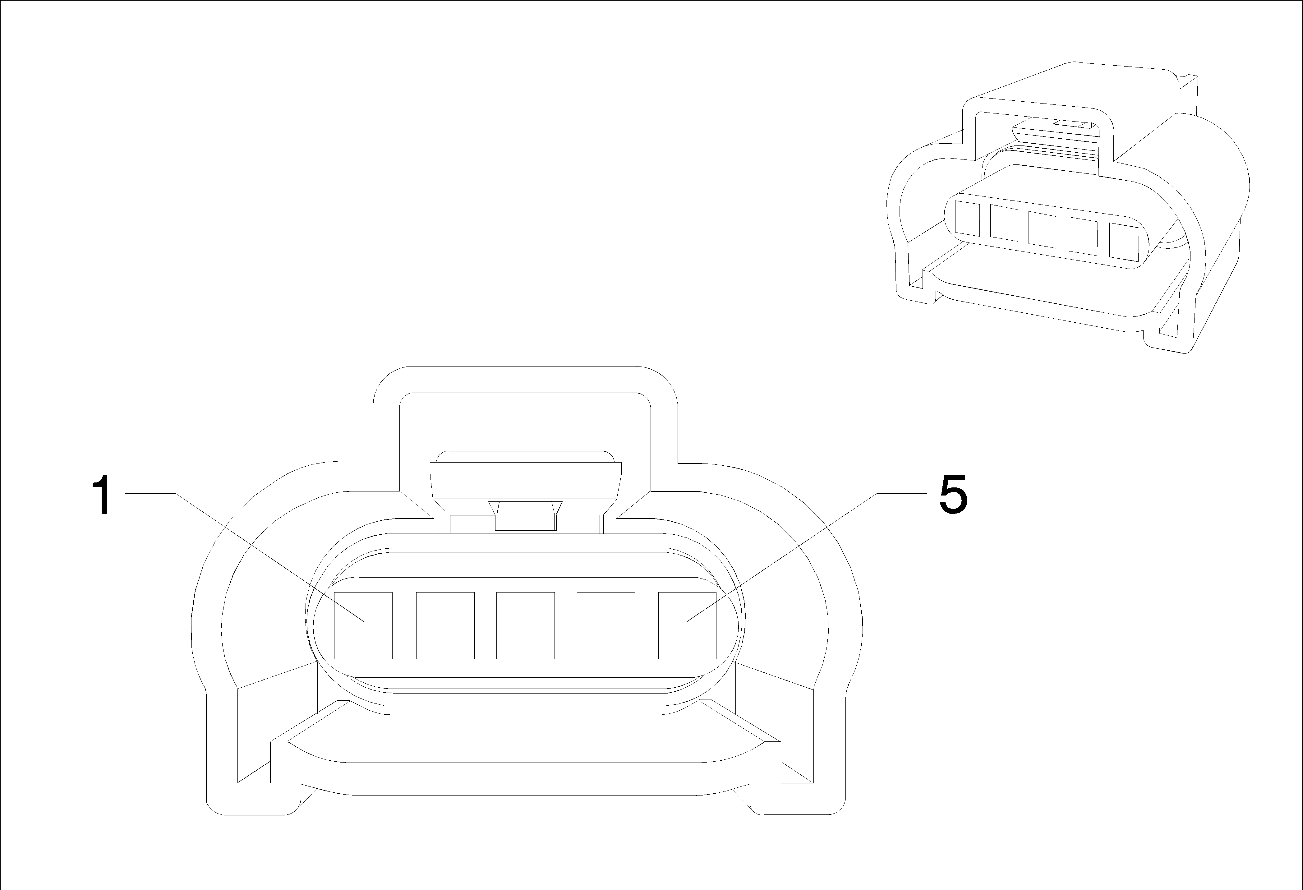
Connector Part Information
|
Terminal Part Information
|
Pin | Wire | Circuit | Function |
|---|---|---|---|
1 | 0.5 Green | 380 | A/C Refrigerant Pressure Sensor Signal (LDE/LXV/2H0) |
0.5 Green | 380 | A/C Refrigerant Pressure Sensor Signal (LLW) | |
0.5 Green | 380 | A/C Refrigerant Pressure Sensor Signal (LXT) | |
2 | 0.5 Brown-Red | 2700 | A/C Pressure Sensor 5 Volt Reference (LDE/LXV/2H0) |
0.5 Brown-Red | 2700 | A/C Pressure Sensor 5 Volt Reference (LLW) | |
0.5 Brown-Red | 2700 | A/C Pressure Sensor 5 Volt Reference (LXT) | |
3 | 0.5 Black-Brown | 5514 | A/C Refrigerant Pressure Sensor Low Reference (LDE/LXV/2H0) |
0.5 Black-Brown | 5514 | A/C Refrigerant Pressure Sensor Low Reference (LLW) | |
0.5 Black-Brown | 5514 | A/C Refrigerant Pressure Sensor Low Reference (LXT) | |
4 | 0.5 Green-Violet | 2032 | Coolant Temperature Sensor Signal (LDE/LXV/2H0) |
5 | 0.5 Black-Blue | 6813 | Coolant Temperature Sensor #2 Low Reference (LDE/LXV/2H0) |
X114 Body Harness & Electrical Power Steering Harness
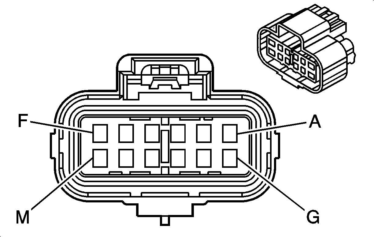
Connector Part Information
|
Terminal Part Information
|
Pin | Wire | Circuit | Function |
|---|---|---|---|
A | 0.5 Blue | 2500 | High Speed GMLAN Serial Data (+) (1) |
B | 0.5 White | 2501 | High Speed GMLAN Serial Data (-) (1) |
C | 0.5 Blue | 2500 | High Speed GMLAN Serial Data (+) (1) |
D | 0.5 White | 2501 | High Speed GMLAN Serial Data (-) (1) |
K | 0.5 White-Blue | 5986 | Serial Data Communication Enable |
X114 Body Harness & Electrical Power Steering Harness

Connector Part Information
|
Terminal Part Information
|
Pin | Wire | Circuit | Function |
|---|---|---|---|
A | 0.5 Blue | 2500 | High Speed GMLAN Serial Data (+) (1) (NJ1) |
B | 0.5 White | 2501 | High Speed GMLAN Serial Data (-) (1) (NJ1) |
C | 0.5 Blue | 2500 | High Speed GMLAN Serial Data (+) (1) (NJ1) |
D | 0.5 White | 2501 | High Speed GMLAN Serial Data (-) (1) (NJ1) |
K | 0.5 White-Blue | 5986 | Serial Data Communication Enable (NJ1) |
X115 Body Harness & Electrical Power Steering Harness (NJ1)

Connector Part Information
|
Terminal Part Information
|
Pin | Wire | Circuit | Function |
|---|---|---|---|
X115 Body Harness & Electrical Power Steering Harness (NJ1)

Connector Part Information
|
Terminal Part Information
|
Pin | Wire | Circuit | Function |
|---|---|---|---|
A | 6 Black | 50 | Ground |
0.5 Brown-Green | 1295 | Variable Effort Steering Solenoid Control | |
B | 0.5 Black-Yellow | 6641 | Variable Effort Steering Solenoid Low Reference |
X115 Body Harness & Electrical Power Steering Harness (NV7)

Connector Part Information
|
Terminal Part Information
|
Pin | Wire | Circuit | Function |
|---|---|---|---|
X115 Body Harness & Electrical Power Steering Harness (NV7)
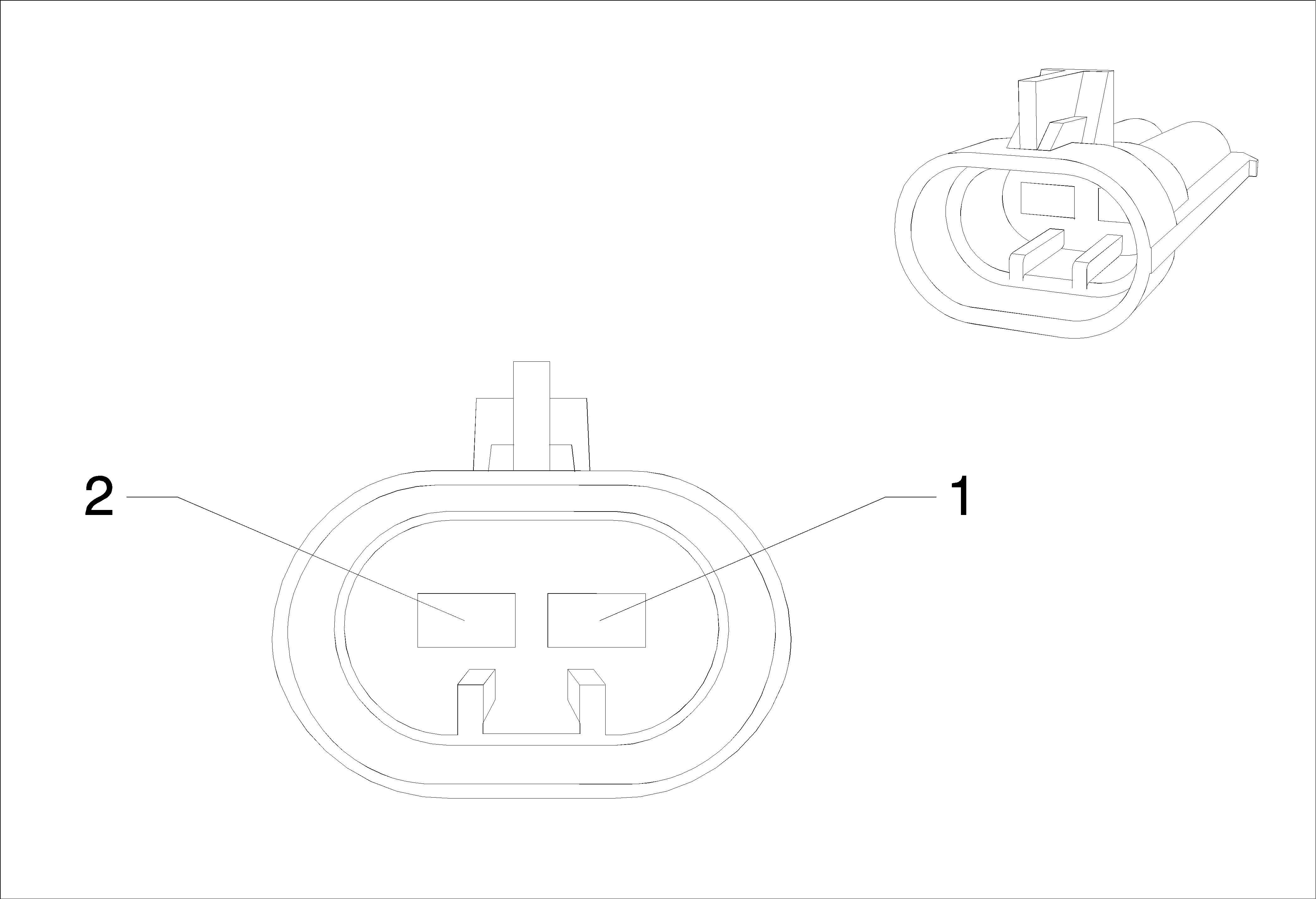
Connector Part Information
|
Terminal Part Information
|
Pin | Wire | Circuit | Function |
|---|---|---|---|
X200 Body Harness & Instrument Panel Harness

Connector Part Information
|
Terminal Part Information
|
Pin | Wire | Circuit | Function |
|---|---|---|---|
1 | 0.75 Blue-Yellow | 1960 | Front Center Speaker (-) (UQG) |
2 | 0.75 Yellow-White | 1860 | Front Center Speaker (+) (UQG) |
8 | 0.5 Brown-Black | 3552 | Passive Start Interior Antenna 1 Signal Hi |
9 | 0.5 Blue | 3554 | Passive Start Interior Antenna 2 Signal Hi |
10 | 0.5 Gray-Black | 3555 | Passive Start Interior Antenna 2 Signal Lo |
11 | 0.5 White | 3553 | Passive Start Interior Antenna 1 Signal Lo |
12 | 0.75 Brown-Blue | 118 | Left Front Speaker Signal (-) (1) (LHD UQG) |
0.75 Brown-Blue | 118 | Left Front Speaker Signal (-) (1) (RHD UQG) | |
13 | 0.75 Yellow-Black | 117 | Right Front Speaker Signal (-) (1) (LHD UQG) |
0.75 Yellow-Black | 117 | Right Front Speaker Signal (-) (1) (RHD UQG) | |
14 | 0.75 Green-Black | 116 | Left Rear Speaker Signal (-) (LHD UQG) |
0.75 Green-Black | 116 | Left Rear Speaker Signal (-) (RHD UQG) | |
15 | 0.75 Blue-Black | 115 | Right Rear Speaker Signal (-) (LHD UQG) |
0.75 Blue-Black | 115 | Right Rear Speaker Signal (-) (RHD UQG) | |
16 | 0.5 Violet-Black | 7553 | Park Lock Solenoid Control |
17 | 0.5 Violet-Black | 3 | Ignition Voltage (ATH) |
19 | 0.5 Blue-Yellow | 6105 | High Speed GMLAN Serial Data (+) (2) |
20 | 0.5 White | 6106 | High Speed GMLAN Serial Data (-) (2) |
21 | 0.5 Red-White | 40 | Battery Positive Voltage |
22 | 0.5 Yellow | 40 | Battery Positive Voltage |
23 | 0.75 Blue | 201 | Left Front Speaker (+) (1) (LHD UQG) |
0.75 Blue | 201 | Left Front Speaker (+) (1) (RHD UQG) | |
24 | 0.75 Yellow | 200 | Right Front Speaker (+) (1) (LHD UQG) |
0.75 Yellow | 200 | Right Front Speaker (+) (1) (RHD UQG) | |
25 | 0.75 Green | 199 | Left Rear Speaker (+) (LHD UQG) |
0.75 Green | 199 | Left Rear Speaker (+) (RHD UQG) | |
26 | 0.75 White | 46 | Right Rear Speaker (+) (LHD UQG) |
0.75 White | 46 | Right Rear Speaker (+) (RHD UQG) | |
27 | 1 Blue-Violet | 807 | OFF /Accessory Voltage |
1 Blue-Violet | 807 | OFF /Accessory Voltage (-ATH) | |
28 | 0.5 Violet-Yellow | 4 | Ignition Voltage (ATH) |
29 | 0.5 Black-Gray | 6110 | Clutch Apply Sensor Low Reference |
30 | 0.5 Yellow | 6111 | Clutch Apply Sensor Signal |
31 | 0.5 Gray-Red | 6109 | Clutch Apply Sensor Voltage Reference |
32 | 0.5 Yellow | 7546 | Logistics Relay Control |
0.5 Yellow | 7546 | Logistics Relay Control (UAG/UFD) | |
0.5 Yellow | 7546 | Logistics Relay Control (UDK) | |
33 | 0.35 Gray-Green | 7565 | Windscreen Temp Sensor Signal (CJ2) |
34 | 0.5 Red-Brown | 40 | Battery Positive Voltage (ATH) |
0.5 Red-Violet | 40 | Battery Positive Voltage (ATH) | |
35 | 0.5 Dark Green | 5103 | Technology Identification |
0.5 Green-Black | 5103 | Technology Identification | |
0.5 Green-Black | 5103 | Technology Identification (UAG/UFD) | |
0.5 Green-Black | 5103 | Technology Identification (UDK) | |
36 | 0.5 Yellow-Green | 3274 | Remote Function Actuator Transmit Signal |
37 | 0.5 Blue-White | 3275 | Remote Function Actuator Receive Signal |
38 | 0.5 Gray-White | 3272 | Remote Function Actuator Supply Voltage |
39 | 0.5 Gray | 3273 | Remote Function Actuator Return |
40 | 0.75 Green-Violet | 1601 | Steering Column Lock Signal |
41 | 0.5 Blue-Gray | 636 | Outside Ambient Air Temperature Sensor Signal |
42 | 0.5 Green-Black | 3358 | Left TV Audio Return (ATH) |
0.5 Green-Black | 3558 | Passive Start Switch Signal 2 (ATH) | |
43 | 0.5 Black-Gray | 3359 | Right TV Audio Return (ATH) |
0.5 Black-Gray | 3559 | Passive Start Switch 2 Low Reference (ATH) | |
44 | 0.35 Yellow-Blue | 3197 | Humidity Temperature Sensor Signal (CJ2) |
45 | 0.5 Yellow-White | 1161 | Accelerator Pedal Position Signal (1) (LDE/LXV/2H0) |
0.5 Yellow-White | 1161 | Accelerator Pedal Position Signal (1) (LLW) | |
0.5 Yellow-White | 1161 | Accelerator Pedal Position Signal (1) (LXT -SAE) | |
46 | 0.5 Black-Blue | 1271 | Accelerator Pedal Position Low Reference (1) (LDE/LXV/2H0) |
0.5 Black-Blue | 1271 | Accelerator Pedal Position Low Reference (1) (LLW) | |
0.5 Black-Blue | 1271 | Accelerator Pedal Position Low Reference (1) (LXT -SAE) | |
47 | 0.5 Black-Violet | 1272 | Accelerator Pedal Position Low Reference (2) (LDE/LXV/2H0) |
0.5 Black-Violet | 1272 | Accelerator Pedal Position Low Reference (2) (LLW) | |
0.5 Black-Violet | 1272 | Accelerator Pedal Position Low Reference (2) (LXT -SAE) | |
48 | 0.5 Green-White | 1162 | Accelerator Pedal Position Signal (2) (LDE/LXV/2H0) |
0.5 Green-White | 1162 | Accelerator Pedal Position Signal (2) (LLW) | |
0.5 Green-White | 1162 | Accelerator Pedal Position Signal (2) (LXT -SAE) | |
49 | 0.5 Black-Blue | 61 | Outside Ambient Temperature Sensor Low Reference |
50 | 0.35 Violet-White | 5203 | Air Quality Sensor Signal |
51 | 0.5 Green-Gray | 6135 | Linear Interconnect Network Bus 4 |
52 | 0.5 Violet-Green | 39 | Ignition Voltage |
53 | 0.5 Violet-Green | 39 | Ignition Voltage |
0.5 Violet-Green | 3039 | Run/Crank Ignition 1 Voltage | |
54 | 0.5 Red-Green | 40 | Battery Positive Voltage |
55 | 0.5 Red-Blue | 40 | Battery Positive Voltage |
0.5 Red-Blue | 840 | Battery Positive Voltage | |
57 | 0.5 Brown-Yellow | 39 | Ignition Voltage |
0.5 Brown-Yellow | 239 | Ignition Voltage | |
58 | 0.75 Gray-Yellow | 6188 | Lift Glass/Trunk Motor Release Control |
59 | 1 White-Brown | 6815 | Inadvertent Power Control |
60 | 0.5 Brown-Yellow | 189 | Headlamp Leveling Motor Control |
61 | 0.5 Brown-Violet | 193 | Rear Defog Relay Control |
62 | 0.35 Black-Blue | 7566 | Humidity/Windscreen Temp Sensor Low Reference (CJ2) |
0.35 Dark Green | 50 | Ground | |
63 | 0.35 Gray-Blue | 7564 | Humidity Sensor Signal (CJ2) |
64 | 0.35 Yellow-Red | 597 | 5 Volt Reference (CJ2) |
65 | 0.5 Brown-Red | 1274 | Accelerator Pedal Position 5 Volt Reference (2) (LDE/LXV/2H0) |
0.5 Brown-Red | 1274 | Accelerator Pedal Position 5 Volt Reference (2) (LLW) | |
0.5 Brown-Red | 1274 | Accelerator Pedal Position 5 Volt Reference (2) (LXT -SAE) | |
66 | 0.5 White-Red | 1164 | Accelerator Pedal Position 5 Volt Reference (1) (LDE/LXV/2H0) |
0.5 White-Red | 1164 | Accelerator Pedal Position 5 Volt Reference (1) (LLW) | |
0.5 White-Red | 1164 | Accelerator Pedal Position 5 Volt Reference (1) (LXT -SAE) | |
67 | 0.5 White-Violet | 5905 | Key Capture/Column Lock Shift Position Signal (ATH) |
68 | 0.5 Green-Brown | 2087 | Combined Vehicle Inertial Sensor Supply Voltage (FX3) |
69 | 0.5 Blue-Yellow | 6795 | Lift Glass/Trunk Motor Release Control 2 |
70 | 0.5 Violet-White | 239 | Ignition Voltage |
71 | 0.5 Violet-White | 239 | Ignition Voltage |
0.5 Violet-White | 39 | Ignition Voltage | |
72 | 0.5 Gray-Green | 328 | Interior Lamp Defeat Switch Signal |
73 | 0.5 Yellow | 5191 | Noise Reduction Microphone Active Signal |
74 | 0.5 BARE | 5193 | Noise Reduction Microphone Screen |
78 | 0.5 Brown-White | 5043 | Keyword 2000 Serial Data |
79 | 0.5 Brown-White | 419 | Check Engine Indicator Control |
80 | 0.5 Dark Blue | 507 | Wait To Start Indicator Control |
0.5 Dark Blue | 507 | Wait To Start Indicator Control (LLW) | |
81 | 0.5 Blue-Yellow | 6105 | High Speed GMLAN Serial Data (+) (2) |
82 | 0.5 White | 6106 | High Speed GMLAN Serial Data (-) (2) |
83 | 0.5 Violet-Green | 239 | Ignition Voltage |
84 | 0.5 Red-Brown | 3 | Ignition Voltage |
0.5 Violet-Black | 3 | Ignition Voltage | |
0.5 Violet-Black | 3 | Ignition Voltage (ATH) | |
0.5 Violet-Black | 3 | Ignition Voltage (-ATH) | |
85 | 0.5 Gray | 1903 | AAS Wheel Speed Sensor Signal Left Front |
0.5 Gray | 1903 | AAS Wheel Speed Sensor Signal Left Front (UDK) | |
87 | 0.5 Blue | 2500 | High Speed GMLAN Serial Data (+) (1) |
88 | 0.5 White | 2501 | High Speed GMLAN Serial Data (-) (1) |
89 | 10 Red-Yellow | 40 | Battery Positive Voltage |
90 | 10 Red-Green | 40 | Battery Positive Voltage |
91 | 1.5 Red-Brown | 702 | Battery Positive Voltage (LHD) |
1.5 Red-Brown | 702 | Battery Positive Voltage (RHD) | |
1.5 Red-Brown | 702 | Battery Positive Voltage (LHD ADS) | |
1.5 Red-Brown | 702 | Battery Positive Voltage (RHD ADS) |
X200 Body Harness & Instrument Panel Harness
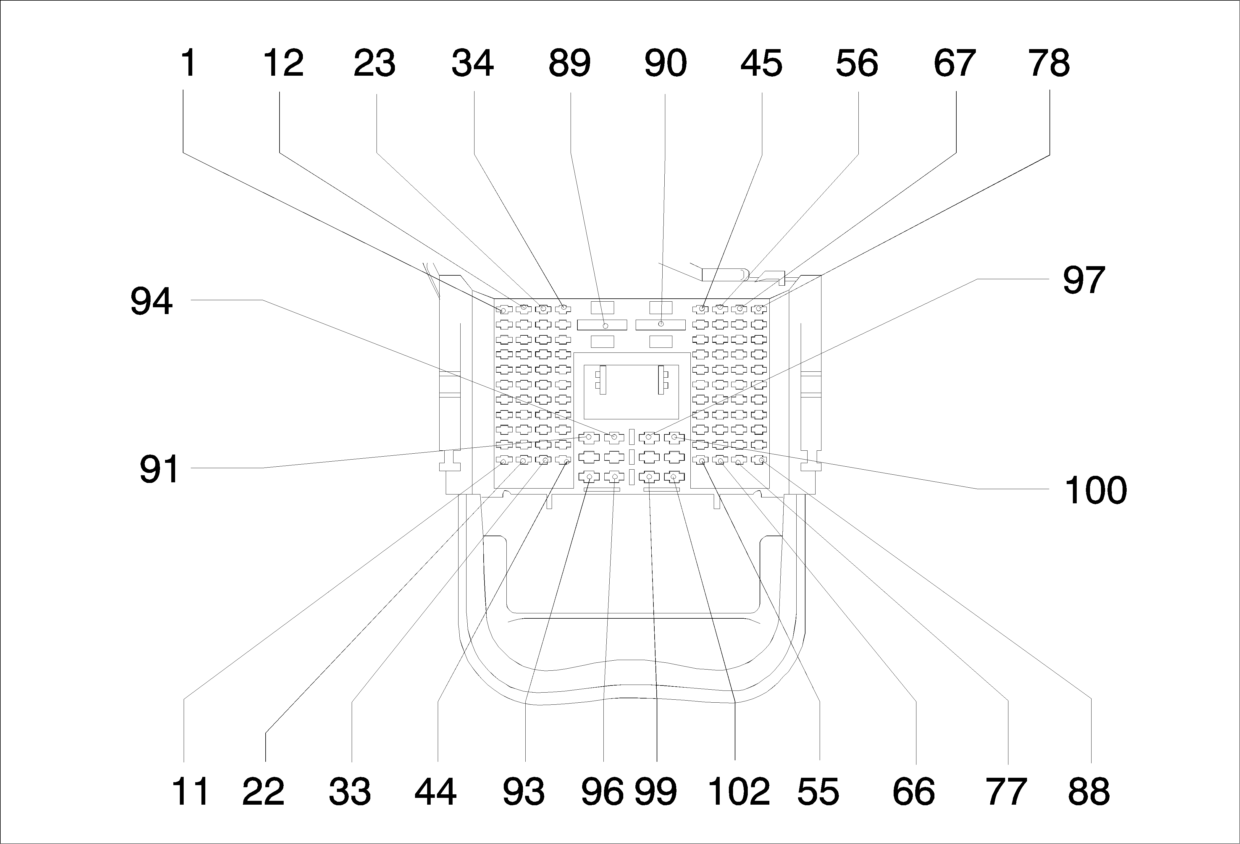
Connector Part Information
|
Terminal Part Information
|
Pin | Wire | Circuit | Function |
|---|---|---|---|
1 | 0.75 Blue-Yellow | 1960 | Front Center Speaker (-) (UQG) |
2 | 0.75 Yellow-White | 1860 | Front Center Speaker (+) (UQG) |
8 | 0.5 Brown-Black | 3552 | Passive Start Interior Antenna 1 Signal Hi |
9 | 0.5 Blue | 3554 | Passive Start Interior Antenna 2 Signal Hi |
10 | 0.5 Gray-Black | 3555 | Passive Start Interior Antenna 2 Signal Lo |
11 | 0.5 White | 3553 | Passive Start Interior Antenna 1 Signal Lo |
12 | 0.75 Brown-Blue | 118 | Left Front Speaker Signal (-) (1) (LHD UQG) |
0.75 Brown-Blue | 118 | Left Front Speaker Signal (-) (1) (RHD UQG) | |
13 | 0.75 Yellow-Black | 117 | Right Front Speaker Signal (-) (1) (LHD UQG) |
0.75 Yellow-Black | 117 | Right Front Speaker Signal (-) (1) (RHD UQG) | |
14 | 0.75 Green-Black | 116 | Left Rear Speaker Signal (-) (LHD UQG) |
0.75 Green-Black | 116 | Left Rear Speaker Signal (-) (RHD UQG) | |
15 | 0.75 Blue-Black | 115 | Right Rear Speaker Signal (-) (LHD UQG) |
0.75 Blue-Black | 115 | Right Rear Speaker Signal (-) (RHD UQG) | |
16 | 0.5 Violet-Black | 7553 | Park Lock Solenoid Control |
17 | 0.5 Violet-Black | 3 | Ignition Voltage (ATH) |
19 | 0.5 Blue-Yellow | 6105 | High Speed GMLAN Serial Data (+) (2) |
20 | 0.5 White | 6106 | High Speed GMLAN Serial Data (-) (2) |
21 | 0.5 Red-White | 40 | Battery Positive Voltage |
22 | 0.5 Yellow | 40 | Battery Positive Voltage |
23 | 0.75 Blue | 201 | Left Front Speaker (+) (1) (LHD UQG) |
0.75 Blue | 201 | Left Front Speaker (+) (1) (RHD UQG) | |
24 | 0.75 Yellow | 200 | Right Front Speaker (+) (1) (LHD UQG) |
0.75 Yellow | 200 | Right Front Speaker (+) (1) (RHD UQG) | |
25 | 0.75 Green | 199 | Left Rear Speaker (+) (LHD UQG) |
0.75 Green | 199 | Left Rear Speaker (+) (RHD UQG) | |
26 | 0.75 White | 46 | Right Rear Speaker (+) (LHD UQG) |
0.75 White | 46 | Right Rear Speaker (+) (RHD UQG) | |
27 | 1 Blue-Violet | 807 | OFF /Accessory Voltage |
1 Blue-Violet | 807 | OFF /Accessory Voltage (-ATH) | |
28 | 0.5 Violet-Yellow | 4 | Ignition Voltage (ATH) |
29 | 0.5 Black-Gray | 6110 | Clutch Apply Sensor Low Reference |
30 | 0.5 Yellow | 6111 | Clutch Apply Sensor Signal |
31 | 0.5 Gray-Red | 6109 | Clutch Apply Sensor Voltage Reference |
32 | 0.5 Yellow | 7546 | Logistics Relay Control |
0.5 Yellow | 7546 | Logistics Relay Control (UAG/UFD) | |
0.5 Yellow | 7546 | Logistics Relay Control (UDK) | |
33 | 0.35 Gray-Green | 7565 | Windscreen Temp Sensor Signal (CJ2) |
34 | 0.5 Red-Brown | 40 | Battery Positive Voltage |
0.5 Red-Violet | 40 | Battery Positive Voltage (ATH) | |
35 | 0.5 Dark Green | 5103 | Technology Identification |
0.5 Green-Black | 5103 | Technology Identification | |
0.5 Green-Black | 5103 | Technology Identification (UAG/UFD) | |
0.5 Green-Black | 5103 | Technology Identification (UDK) | |
36 | 0.5 Yellow-Green | 3274 | Remote Function Actuator Transmit Signal |
37 | 0.5 Blue-White | 3275 | Remote Function Actuator Receive Signal |
38 | 0.5 Gray-White | 3272 | Remote Function Actuator Supply Voltage |
39 | 0.5 Gray | 3273 | Remote Function Actuator Return |
40 | 0.75 Green-Violet | 1601 | Steering Column Lock Signal |
41 | 0.5 Blue-Gray | 636 | Outside Ambient Air Temperature Sensor Signal |
42 | 0.5 Green-Black | 3358 | Left TV Audio Return (ATH) |
0.5 Green-Black | 3558 | Passive Start Switch Signal 2 (ATH) | |
43 | 0.5 Black-Gray | 3359 | Right TV Audio Return (ATH) |
0.5 Black-Gray | 3559 | Passive Start Switch 2 Low Reference (ATH) | |
44 | 0.35 Yellow-Blue | 3197 | Humidity Temperature Sensor Signal (CJ2) |
45 | 0.5 Yellow-White | 1161 | Accelerator Pedal Position Signal (1) (LDE/LXV/2H0) |
0.5 Yellow-White | 1161 | Accelerator Pedal Position Signal (1) (LLW) | |
0.5 Yellow-White | 1161 | Accelerator Pedal Position Signal (1) (LXT -SAE) | |
46 | 0.5 Black-Blue | 1271 | Accelerator Pedal Position Low Reference (1) (LDE/LXV/2H0) |
0.5 Black-Blue | 1271 | Accelerator Pedal Position Low Reference (1) (LLW) | |
0.5 Black-Blue | 1271 | Accelerator Pedal Position Low Reference (1) (LXT -SAE) | |
47 | 0.5 Black-Violet | 1272 | Accelerator Pedal Position Low Reference (2) (LDE/LXV/2H0) |
0.5 Black-Violet | 1272 | Accelerator Pedal Position Low Reference (2) (LLW) | |
0.5 Black-Violet | 1272 | Accelerator Pedal Position Low Reference (2) (LXT -SAE) | |
48 | 0.5 Green-White | 1162 | Accelerator Pedal Position Signal (2) (LDE/LXV/2H0) |
0.5 Green-White | 1162 | Accelerator Pedal Position Signal (2) (LLW) | |
0.5 Green-White | 1162 | Accelerator Pedal Position Signal (2) (LXT -SAE) | |
49 | 0.5 Black-Blue | 61 | Outside Ambient Temperature Sensor Low Reference |
50 | 0.5 Violet-White | 5203 | Air Quality Sensor Signal |
51 | 0.5 Green-Gray | 6135 | Linear Interconnect Network Bus 4 |
52 | 0.5 Violet-Green | 39 | Ignition Voltage |
53 | 0.5 Violet-Green | 39 | Ignition Voltage |
0.5 Violet-Green | 3039 | Run/Crank Ignition 1 Voltage | |
54 | 0.5 Red-Green | 40 | Battery Positive Voltage |
55 | 0.5 Red-Blue | 840 | Battery Positive Voltage |
57 | 0.5 Brown-Yellow | 39 | Ignition Voltage |
0.5 Brown-Yellow | 239 | Ignition Voltage | |
58 | 0.75 Gray-Yellow | 6188 | Lift Glass/Trunk Motor Release Control |
59 | 0.5 White-Brown | 6815 | Inadvertent Power Control (GLV) |
60 | 0.5 Brown-Yellow | 189 | Headlamp Leveling Motor Control |
61 | 0.5 Brown-Violet | 193 | Rear Defog Relay Control |
62 | - - | - | - (CJ2) |
0.35 Dark Green | 50 | Ground | |
63 | 0.35 Gray-Blue | 7564 | Humidity Sensor Signal (CJ2) |
64 | 0.35 Yellow-Red | 597 | 5 Volt Reference (CJ2) |
65 | 0.5 Brown-Red | 1274 | Accelerator Pedal Position 5 Volt Reference (2) (LDE/LXV/2H0) |
0.5 Brown-Red | 1274 | Accelerator Pedal Position 5 Volt Reference (2) (LLW) | |
0.5 Brown-Red | 1274 | Accelerator Pedal Position 5 Volt Reference (2) (LXT -SAE) | |
66 | 0.5 White-Red | 1164 | Accelerator Pedal Position 5 Volt Reference (1) (LDE/LXV/2H0) |
0.5 White-Red | 1164 | Accelerator Pedal Position 5 Volt Reference (1) (LLW) | |
0.5 White-Red | 1164 | Accelerator Pedal Position 5 Volt Reference (1) (LXT -SAE) | |
67 | 0.5 White-Violet | 5905 | Key Capture/Column Lock Shift Position Signal |
68 | 0.5 Green-Brown | 2087 | Combined Vehicle Inertial Sensor Supply Voltage (FX3) |
69 | 0.5 Blue-Yellow | 6795 | Lift Glass/Trunk Motor Release Control 2 |
70 | 0.5 Violet-White | 239 | Ignition Voltage |
71 | 0.5 Violet-White | 239 | Ignition Voltage |
0.5 Violet-White | 39 | Ignition Voltage | |
72 | 0.5 Gray-Green | 328 | Interior Lamp Defeat Switch Signal |
73 | 0.5 Yellow | 5191 | Noise Reduction Microphone Active Signal |
74 | 0.5 BARE | 5193 | Noise Reduction Microphone Screen |
78 | 0.5 Brown-White | 5043 | Keyword 2000 Serial Data |
79 | 0.5 Brown-White | 419 | Check Engine Indicator Control |
80 | 0.5 Dark Blue | 507 | Wait To Start Indicator Control |
0.5 Dark Blue | 507 | Wait To Start Indicator Control (LLW) | |
81 | 0.5 Blue-Yellow | 6105 | High Speed GMLAN Serial Data (+) (2) |
82 | 0.5 White | 6106 | High Speed GMLAN Serial Data (-) (2) |
83 | 0.5 Violet-Green | 239 | Ignition Voltage |
84 | 0.5 Violet-Black | 3 | Ignition Voltage |
0.5 Violet-Black | 3 | Ignition Voltage (ATH) | |
0.5 Violet-Black | 3 | Ignition Voltage (-ATH) | |
85 | 0.5 Gray | 1903 | AAS Wheel Speed Sensor Signal Left Front |
0.5 Gray | 1903 | AAS Wheel Speed Sensor Signal Left Front (UDK) | |
87 | 0.5 Blue | 2500 | High Speed GMLAN Serial Data (+) (1) (JL9) |
0.5 Blue | 2500 | High Speed GMLAN Serial Data (+) (1) (JL9 -SAE) | |
0.5 Blue | 2500 | High Speed GMLAN Serial Data (+) (1) (SAE) | |
88 | 0.5 White | 2501 | High Speed GMLAN Serial Data (-) (1) (JL9) |
0.5 White | 2501 | High Speed GMLAN Serial Data (-) (1) (JL9 -SAE) | |
0.5 White | 2501 | High Speed GMLAN Serial Data (-) (1) (SAE) | |
89 | 10 Red-Yellow | 40 | Battery Positive Voltage |
90 | 10 Red-Green | 40 | Battery Positive Voltage |
91 | 1.5 Red-Brown | 702 | Battery Positive Voltage |
1.5 Red-Brown | 702 | Battery Positive Voltage (LHD ADS) | |
1.5 Red-Brown | 702 | Battery Positive Voltage (RHD ADS) |
X205 Body Harness & Instrument Panel Harness
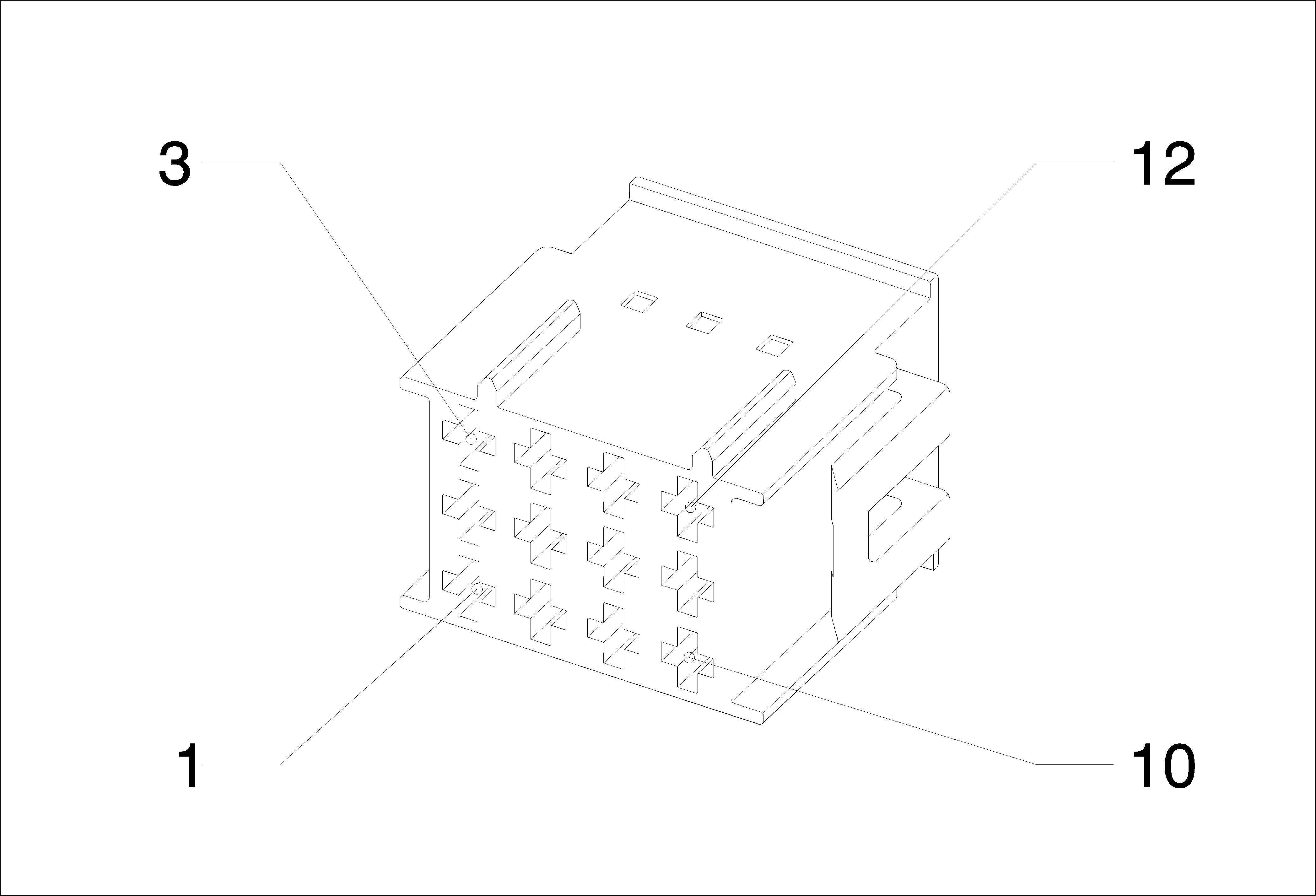
Connector Part Information
|
Terminal Part Information
|
Pin | Wire | Circuit | Function |
|---|---|---|---|
1 | 0.35 Blue-Black | 1946 | Right Rear Low Level Audio (-) |
2 | 0.35 BARE | 2099 | Left Rear Audio Drain Wire |
3 | 0.35 Blue-Brown | 1546 | Front Low Level Audio (-) |
4 | 0.35 Brown-Violet | 1999 | Left Rear Low Level Audio (-) |
5 | 0.5 Violet-Blue | 6978 | Amplifier Control (UQG) |
6 | 0.35 Yellow | 512 | Right Front Low Level Audio Signal |
7 | 0.35 Brown-White | 546 | Right Rear Low Level Audio Signal |
8 | 0.5 Green-Yellow | 7066 | Entertainment Remote Enable Signal (UQG) |
9 | 0.35 Brown-Blue | 1947 | Left Front Low Level Audio (-) |
10 | 0.35 Green-Black | 599 | Left Rear Low Level Audio Signal |
11 | 0.35 BARE | 2011 | Left Front Audio Drain Wire |
12 | 0.35 Blue | 511 | Left Front Low Level Audio Signal |
X205 Body Harness & Instrument Panel Harness
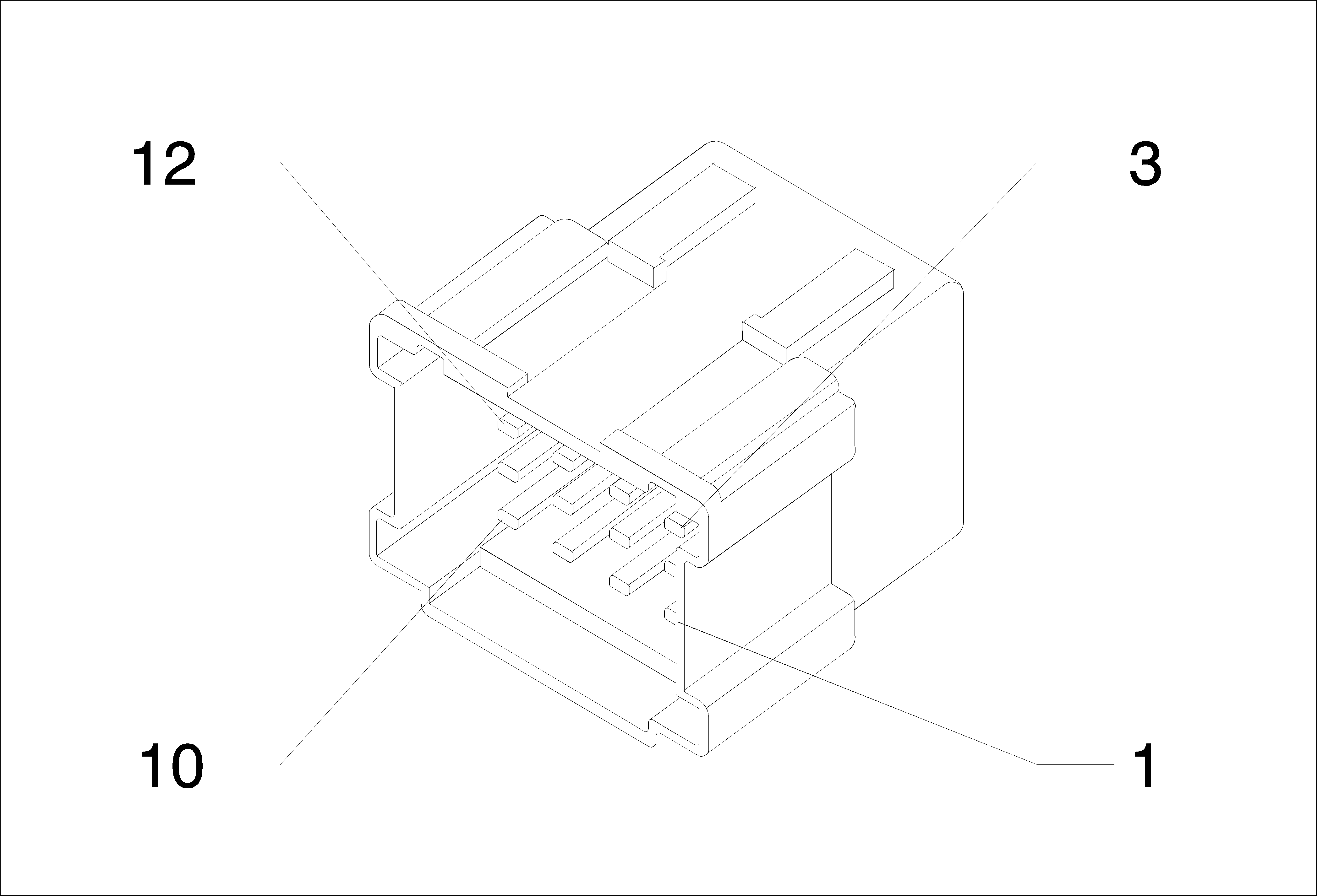
Connector Part Information
|
Terminal Part Information
|
Pin | Wire | Circuit | Function |
|---|---|---|---|
1 | 0.35 Blue-Black | 1946 | Right Rear Low Level Audio (-) |
2 | 0.35 BARE | 2099 | Left Rear Audio Drain Wire |
3 | 0.35 Blue-Brown | 1546 | Front Low Level Audio (-) |
4 | 0.35 Brown-Violet | 1999 | Left Rear Low Level Audio (-) |
5 | 0.5 Violet-Blue | 6978 | Amplifier Control |
6 | 0.35 Yellow | 512 | Right Front Low Level Audio Signal |
7 | 0.35 Brown-White | 546 | Right Rear Low Level Audio Signal |
8 | 0.5 Green-Yellow | 7066 | Entertainment Remote Enable Signal |
9 | 0.35 Brown-Blue | 1947 | Left Front Low Level Audio (-) |
10 | 0.35 Green-Black | 599 | Left Rear Low Level Audio Signal |
11 | 0.35 BARE | 2011 | Left Front Audio Drain Wire |
12 | 0.35 Blue | 511 | Left Front Low Level Audio Signal |
X300 Instrument Panel Harness & Console Harness
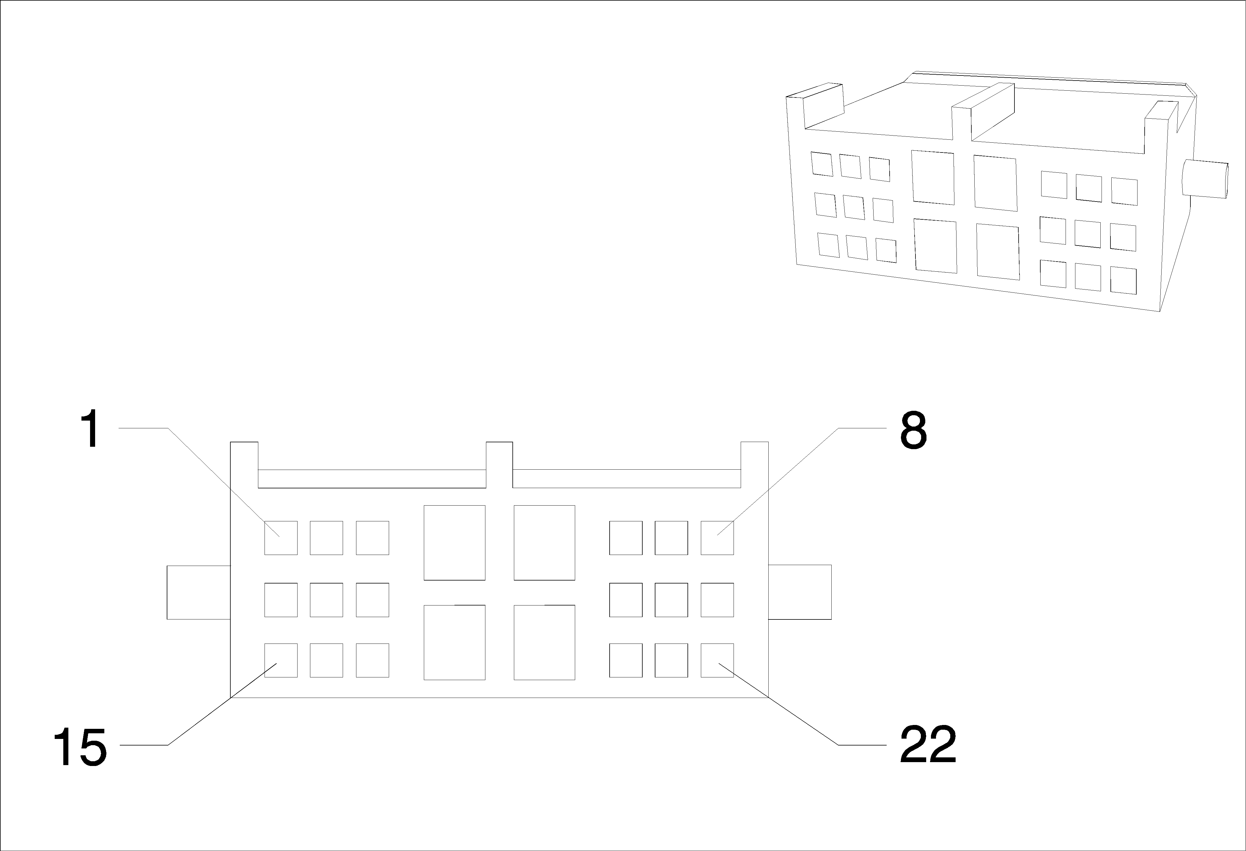
Connector Part Information
|
Terminal Part Information
|
Pin | Wire | Circuit | Function |
|---|---|---|---|
1 | 0.5 Brown | 3345 | Hands Free Kit Jack Common Serial Data |
2 | 0.5 White | 3346 | Hands Free Kit Telephone Jack TX Serial Data |
3 | 0.5 Gray | 3347 | Hands Free Kit Telephone Jack RX Serial Data |
4 | 1 Black | 50 | Ground |
5 | 1 Violet | 801 | Retained Accessory Power Fuse Supply Voltage |
6 | 0.5 Blue | 3554 | Passive Start Interior Antenna 2 Signal Hi |
8 | 0.5 Black | 50 | Ground |
9 | 0.5 Green | 3348 | Hands Free Kit Headphone Jack TX Serial Data |
10 | 0.5 Blue | 3349 | Hands Free Kit Headphone Jack RX Serial Data |
11 | 0.5 Green-Gray | 3277 | Vehicle Anti-Theft System Immobilizer Return (ATH) |
12 | 0.35 Green | 5841 | Right Auxiliary Audio Signal (2) |
13 | 0.35 Violet | 5843 | Auxiliary Audio Common Signal |
14 | 0.35 Gray | 5839 | Left Auxiliary Audio Signal (2) |
15 | 0.5 Green-Violet | 7533 | Linear Interconnect Network Bus 11 (ATH) |
16 | 0.5 Blue-Violet | 1788 | Traction Control Switch Signal (1) |
17 | 0.5 Gray-Black | 3276 | Vehicle Anti-Theft System Immobilizer Supply Voltage (ATH) |
18 | 1 Black | 50 | Ground |
19 | 1 Violet | 801 | Retained Accessory Power Fuse Supply Voltage |
20 | 0.5 Gray-Black | 3555 | Passive Start Interior Antenna 2 Signal Lo |
21 | 0.35 BARE | 5842 | Auxiliary Audio Screen (2) |
22 | 0.35 Blue | 2060 | Auxiliary Detection Signal |
X310 Body Harness & Driver Seat Harness (LHD)

Connector Part Information
|
Terminal Part Information
|
Pin | Wire | Circuit | Function |
|---|---|---|---|
1 | 1.5 Black | 50 | Ground |
2 | 2.5 Black | 50 | Ground |
3 | 1 Black-Blue | 2433 | Passenger Heated Back Element Return |
7 | 0.5 Black-Orange | 1363 | Driver Seat Belt Switch Low Reference |
8 | 0.5 Orange-Brown | 238 | Driver Seat Belt Switch Signal |
28 | 0.5 Yellow-Orange | 2138 | Left Front Side Impact Module Low Control |
30 | 0.5 Orange-Blue | 2137 | Left Front Side Impact Module High Control |
43 | 0.5 Green | 5060 | Low Speed GMLAN Serial Data |
44 | 0.5 Black-Gray | 2435 | Passenger Heated Seat NTC Low Reference |
45 | 0.5 White-Gray | 2434 | Passenger Heated Seat NTC Signal |
46 | 1 Brown-Blue | 2479 | Passenger Heated Seat Element Control |
47 | 2.5 Red-Green | 40 | Battery Positive Voltage |
2.5 Red-White | 40 | Battery Positive Voltage | |
48 | 1.5 Red-Brown | 702 | Battery Positive Voltage |
1.5 Red-Brown | 702 | Battery Positive Voltage (LHD ADS) |
X310 Body Harness & Driver Seat Harness (RHD)

Connector Part Information
|
Terminal Part Information
|
Pin | Wire | Circuit | Function |
|---|---|---|---|
1 | 1.5 Black | 50 | Ground |
2 | 2.5 Black | 50 | Ground |
3 | 1 Black-Blue | 2433 | Passenger Heated Back Element Return |
7 | 0.5 Black-Orange | 1363 | Driver Seat Belt Switch Low Reference |
8 | 0.5 Orange-Brown | 238 | Driver Seat Belt Switch Signal |
28 | 0.5 Yellow-Orange | 2138 | Left Front Side Impact Module Low Control |
30 | 0.5 Orange-Blue | 2137 | Left Front Side Impact Module High Control |
43 | 0.5 Green | 5060 | Low Speed GMLAN Serial Data |
44 | 0.5 Black-Gray | 2435 | Passenger Heated Seat NTC Low Reference |
45 | 0.5 White-Gray | 2434 | Passenger Heated Seat NTC Signal |
46 | 1 Brown-Blue | 2479 | Passenger Heated Seat Element Control |
47 | 2.5 Red-Green | 40 | Battery Positive Voltage |
2.5 Red-White | 40 | Battery Positive Voltage | |
48 | 1.5 Red-Brown | 702 | Battery Positive Voltage |
1.5 Red-Brown | 702 | Battery Positive Voltage (RHD ADS) |
X315 Body Harness & Front Passenger Seat Harness (LHD)

Connector Part Information
|
Terminal Part Information
|
Pin | Wire | Circuit | Function |
|---|---|---|---|
7 | 0.5 Black-Orange | 1361 | Passenger Seat Belt Switch Low Reference |
8 | 0.5 Orange-Violet | 1362 | Passenger Seat Belt Switch Signal |
13 | 0.5 Orange-Brown | 7571 | Passenger Seat Belt Reminder Signal |
16 | 0.5 Red-Gray | 402 | Battery Positive Voltage |
0.5 Red-Gray | 402 | Battery Positive Voltage (AL0) | |
17 | 0.5 Green | 5060 | Low Speed GMLAN Serial Data |
18 | 0.5 Black | 50 | Ground |
28 | 0.5 Green-Orange | 2136 | Right Front Side Impact Module Low Control |
30 | 0.5 Orange-Yellow | 2135 | Right Front Side Impact Module High Control |
44 | 0.5 Black-Gray | 2435 | Passenger Heated Seat NTC Low Reference |
45 | 0.5 White-Gray | 2434 | Passenger Heated Seat NTC Signal |
46 | 1 Black-Blue | 2433 | Passenger Heated Back Element Return |
47 | 1 Brown-Blue | 2479 | Passenger Heated Seat Element Control |
X315 Body Harness & Front Passenger Seat Harness (RHD)

Connector Part Information
|
Terminal Part Information
|
Pin | Wire | Circuit | Function |
|---|---|---|---|
7 | 0.5 Black-Orange | 1361 | Passenger Seat Belt Switch Low Reference |
8 | 0.5 Orange-Violet | 1362 | Passenger Seat Belt Switch Signal |
13 | 0.5 Orange-Brown | 7571 | Passenger Seat Belt Reminder Signal |
16 | 0.5 Red-Gray | 402 | Battery Positive Voltage |
0.5 Red-Gray | 402 | Battery Positive Voltage (AL0) | |
17 | 0.5 Green | 5060 | Low Speed GMLAN Serial Data |
18 | 0.5 Black | 50 | Ground |
28 | 0.5 Green-Orange | 2136 | Right Front Side Impact Module Low Control |
30 | 0.5 Orange-Yellow | 2135 | Right Front Side Impact Module High Control |
44 | 0.5 Black-Gray | 2435 | Passenger Heated Seat NTC Low Reference |
45 | 0.5 White-Gray | 2434 | Passenger Heated Seat NTC Signal |
46 | 1 Black-Blue | 2433 | Passenger Heated Back Element Return |
47 | 1 Brown-Blue | 2479 | Passenger Heated Seat Element Control |
X320 Body Harness & Curtain Airbag Harness
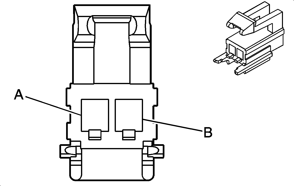
Connector Part Information
|
Terminal Part Information
|
Pin | Wire | Circuit | Function |
|---|---|---|---|
A | 0.5 Orange-Green | 5019 | Left Front Head Curtain Module High Control |
B | 0.5 Violet-Orange | 5020 | Left Front Head Curtain Module Low Control |
X320 Body Harness & Curtain Airbag Harness
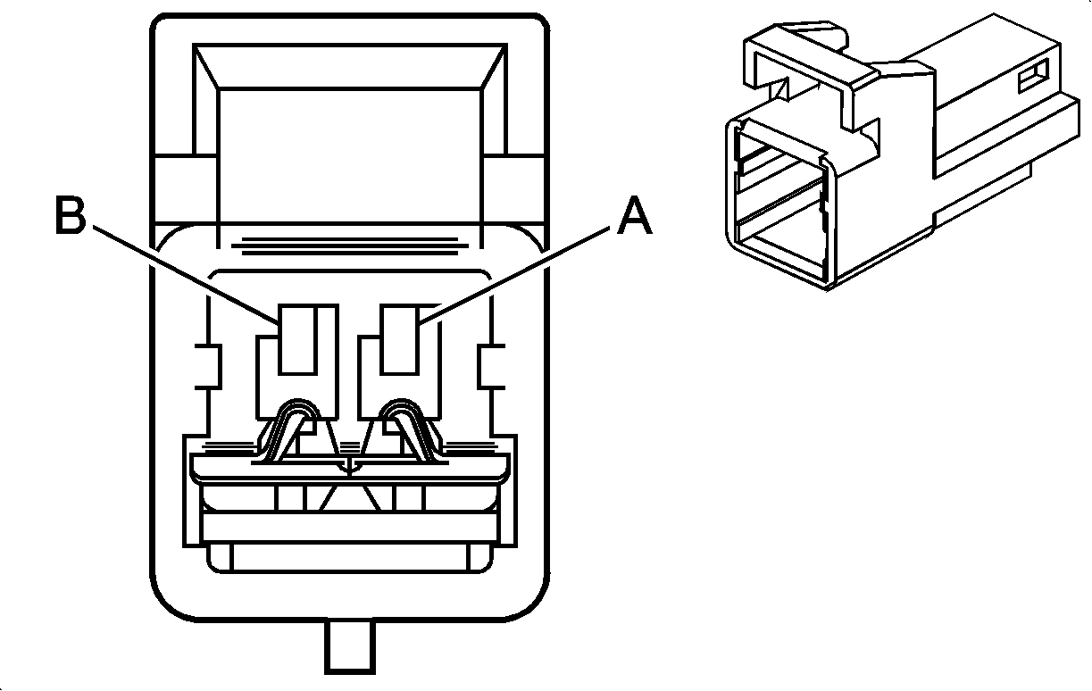
Connector Part Information
|
Terminal Part Information
|
Pin | Wire | Circuit | Function |
|---|---|---|---|
X321 Body Harness & Curtain Airbag Harness

Connector Part Information
|
Terminal Part Information
|
Pin | Wire | Circuit | Function |
|---|---|---|---|
X401 Body Harness & Fuel Tank Harness
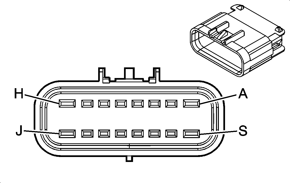
Connector Part Information
|
Terminal Part Information
|
Pin | Wire | Circuit | Function |
|---|---|---|---|
A | -- | -- | -- |
2.5 Gray | 120 | Fuel Pump Control (LDE/LXV/2H0) | |
2.5 Gray | 120 | Fuel Pump Control (SAE LDE OR LXV OR 2H0) | |
2.5 Gray | 120 | Fuel Pump Control (LLW SAE) | |
2.5 Gray | 120 | Fuel Pump Control (LLW -SAE) | |
2.5 Gray | 120 | Fuel Pump Control (LXT SAE) | |
2.5 Gray | 120 | Fuel Pump Control (LXT -SAE) | |
B | 0.5 Blue-Violet | 1589 | Primary Fuel Level Sensor Signal |
D | 0.5 Yellow-Red | 2709 | Fuel Tank Pressure Sensor 5 Volt Reference (LDE/LXV/2H0) |
E | 0.5 White-Brown | 508 | Water In Fuel Indicator Control (LLW) |
0.5 Blue-White | 890 | Fuel Tank Pressure Sensor Signal (LDE/LXV/2H0) | |
F | 0.5 Black-Green | 6281 | Fuel Level Sensor Low Reference (LDE/LXV/2H0) |
H | 0.5 Brown-Red | 7445 | Fuel Line Pressure Sensor 5V Reference (SAE LDE OR LXV OR 2H0) |
0.5 Brown-Red | 7445 | Fuel Line Pressure Sensor 5V Reference (LLW SAE) | |
0.5 Brown-Red | 7445 | Fuel Line Pressure Sensor 5V Reference (LXT SAE) | |
2.5 Red-Blue | 1842 | Battery Positive Voltage | |
2.5 Red-Blue | 1842 | Battery Positive Voltage (LLW) | |
J | 2.5 Black | 50 | Ground |
2.5 Black | 50 | Ground (LLW) | |
K | 0.5 Blue-White | 7446 | Fuel Line Pressure Sensor Signal (SAE LDE OR LXV OR 2H0) |
0.5 Blue-White | 7446 | Fuel Line Pressure Sensor Signal (LLW SAE) | |
0.5 Blue-White | 7446 | Fuel Line Pressure Sensor Signal (LXT SAE) | |
0.5 Yellow-Blue | 1578 | Fuel Temperature Signal (LLW) | |
L | 0.5 Black-Yellow | 7447 | Fuel Line Pressure Sensor Low Reference (SAE LDE OR LXV OR 2H0) |
0.5 Black-Yellow | 7447 | Fuel Line Pressure Sensor Low Reference (LLW SAE) | |
0.5 Black-Yellow | 7447 | Fuel Line Pressure Sensor Low Reference (LXT SAE) | |
0.5 Black-Brown | 6062 | Fuel Temperature Sensor Low Reference (LLW) | |
M | 0.75 Blue | 5372 | Canister Valve Solenoid (LDE/LXV/2H0) |
0.75 Blue | 5372 | Canister Valve Solenoid | |
0.5 Violet-Blue | 5290 | Powertrain Main Relay Fused Supply (1) (LLW) | |
0.5 Violet-Blue | 5290 | Powertrain Main Relay Fused Supply (1) (LLW) | |
N | 0.75 White | 1310 | EVAP Canister Vent Solenoid Control (LDE/LXV/2H0) |
0.5 Black | 50 | Ground | |
0.5 Black | 50 | Ground (LLW) | |
R | 0.5 Black-Green | 6281 | Fuel Level Sensor Low Reference |
S | 2 Black | 50 | Ground (LXT -SAE) |
2.5 Black | 50 | Ground (LLW -SAE) | |
2.5 Black | 50 | Ground | |
2.5 Black | 50 | Ground (LDE/LXV/2H0) | |
2.5 Black-Green | 1580 | Fuel Pump Low Reference (SAE LDE OR LXV OR 2H0) | |
2.5 Black-Green | 1580 | Fuel Pump Low Reference (LLW SAE) | |
2.5 Black-Green | 1580 | Fuel Pump Low Reference (LXT SAE) |
X402 Body Harness & Park Pilot Harness (Female)

Connector Part Information
|
Terminal Part Information
|
Pin | Wire | Circuit | Function |
|---|---|---|---|
A | 0.5 Yellow-Violet | 2378 | Right Rear Corner Object Sensor Signal |
B | 0.5 Yellow-White | 2377 | Right Rear Middle Object Sensor Signal |
C | 0.5 Yellow-Blue | 2376 | Left Rear Middle Object Sensor Signal |
D | - - | - | - |
E | 0.5 Yellow | 2375 | Left Rear Corner Object Sensor Signal |
F | - - | - | - |
X402 Body Harness & Park Pilot Harness

Connector Part Information
|
Terminal Part Information
|
Pin | Wire | Circuit | Function |
|---|---|---|---|
A | 0.5 Yellow-Violet | 2378 | Right Rear Corner Object Sensor Signal |
B | 0.5 Yellow-White | 2377 | Right Rear Middle Object Sensor Signal |
C | 0.5 Yellow-Blue | 2376 | Left Rear Middle Object Sensor Signal |
D | 0.5 Brown-White | 2374 | Object Sensor Control |
E | 0.5 Yellow | 2375 | Left Rear Corner Object Sensor Signal |
F | 0.5 Black-Gray | 2379 | Object Sensor Low Reference |
X500 Body Harness & Driver Door Harness

Connector Part Information
|
Terminal Part Information
|
Pin | Wire | Circuit | Function |
|---|---|---|---|
1 | 2.5 Red-Green | 1540 | Battery Positive Voltage (AEC) |
2.5 Red-Green | 1540 | Battery Positive Voltage (AXG) | |
2.5 Red-Green | 40 | Battery Positive Voltage (AEC) | |
2.5 Red-Green | 40 | Battery Positive Voltage (AXG) | |
2 | 2.5 Black | 50 | Ground (AEC) |
2.5 Black | 50 | Ground (AXG) | |
3 | 1.25 Black | 50 | Ground |
4 | 0.5 Red-Green | 40 | Battery Positive Voltage |
0.5 Red-Green | 40 | Battery Positive Voltage (AXG) | |
8 | 0.5 Black | 50 | Ground (ATH) |
9 | 0.75 Gray | 295 | Door Lock Actuator Lock Control ( -AF8) |
0.75 Gray | 295 | Door Lock Actuator Lock Control ( AF8-SAE) | |
10 | 0.75 Brown-Yellow | 294 | Door Lock Actuator Unlock Control ( -AF8) |
0.75 Brown-Yellow | 294 | Door Lock Actuator Unlock Control ( AF8-SAE) | |
11 | 0.75 Brown | 5910 | Door Double Lock Actuator Lock Control ( AF8-SAE) |
12 | 0.5 Black | 50 | Ground |
13 | 0.5 Dark Blue | 6189 | Lift Glass/Trunk Interior Release Signal |
14 | 0.75 Blue | 201 | Left Front Speaker (+) (1) (LHD UQG) |
0.75 Blue | 201 | Left Front Speaker (+) (1) (LHD UQG) | |
0.75 Yellow | 200 | Right Front Speaker (+) (1) (RHD UQG) | |
0.75 Yellow | 200 | Right Front Speaker (+) (1) (RHD UQG) | |
15 | 0.75 Yellow-Black | 117 | Right Front Speaker Signal (-) (1) (RHD UQG) |
0.75 Yellow-Black | 117 | Right Front Speaker Signal (-) (1) (RHD UQG) | |
0.75 Brown-Blue | 118 | Left Front Speaker Signal (-) (1) (LHD UQG) | |
0.75 Brown-Blue | 118 | Left Front Speaker Signal (-) (1) (LHD UQG) | |
16 | 0.5 Green-White | 6655 | Driver Door Unlatch Switch Signal |
18 | 0.5 Green-Yellow | 6134 | Linear Interconnect Network Bus 3 (AED) |
0.5 Green-Yellow | 6134 | Linear Interconnect Network Bus 3 (AXG) | |
19 | 0.5 Violet-Yellow | 3409 | Mirror Motor Fold Out Control |
20 | 0.5 White-Brown | 3410 | Mirror Motor Fold In Control |
21 | 0.5 Yellow | 6817 | LED Backlight Dimming Control |
22 | 0.5 Green-Black | 3396 | Co-Driver Mirror Motor Right (+) Left (-) Control |
23 | 0.5 White | 3398 | Co-Driver Mirror Motor Common Control |
24 | 0.5 Yellow-Violet | 3397 | Co-Driver Mirror Motor Up (+) Down (-) Control |
25 | 0.75 Black | 50 | Ground (LHD) |
0.75 Black | 50 | Ground (RHD) | |
26 | 0.5 Red-Gray | 40 | Battery Positive Voltage |
27 | 0.5 Gray | 745 | Left Front Door Ajar Switch Signal (-AED/-AXG) |
28 | 0.5 Brown-Yellow | 2267 | Mirror Heating Element Control |
31 | 0.5 Green-White | 3570 | Driver Door Handle Switch Signal |
32 | 0.75 Gray | 3578 | Driver Door Unlatch Motor Unlatch Return (ATH) |
33 | 0.5 Violet-Gray | 3561 | Passive Entry Driver Door Antenna Signal Lo |
34 | 0.5 Violet | 3560 | Passive Entry Driver Door Antenna Signal Hi |
40 | 0.5 White-Yellow | 3574 | Driver Door Open Switch Signal (ATH) |
41 | 0.75 Violet-Blue | 6666 | Driver Door Unlatch Motor Unlatch Control (ATH) |
X500 Body Harness & Driver Door Harness (LHD)
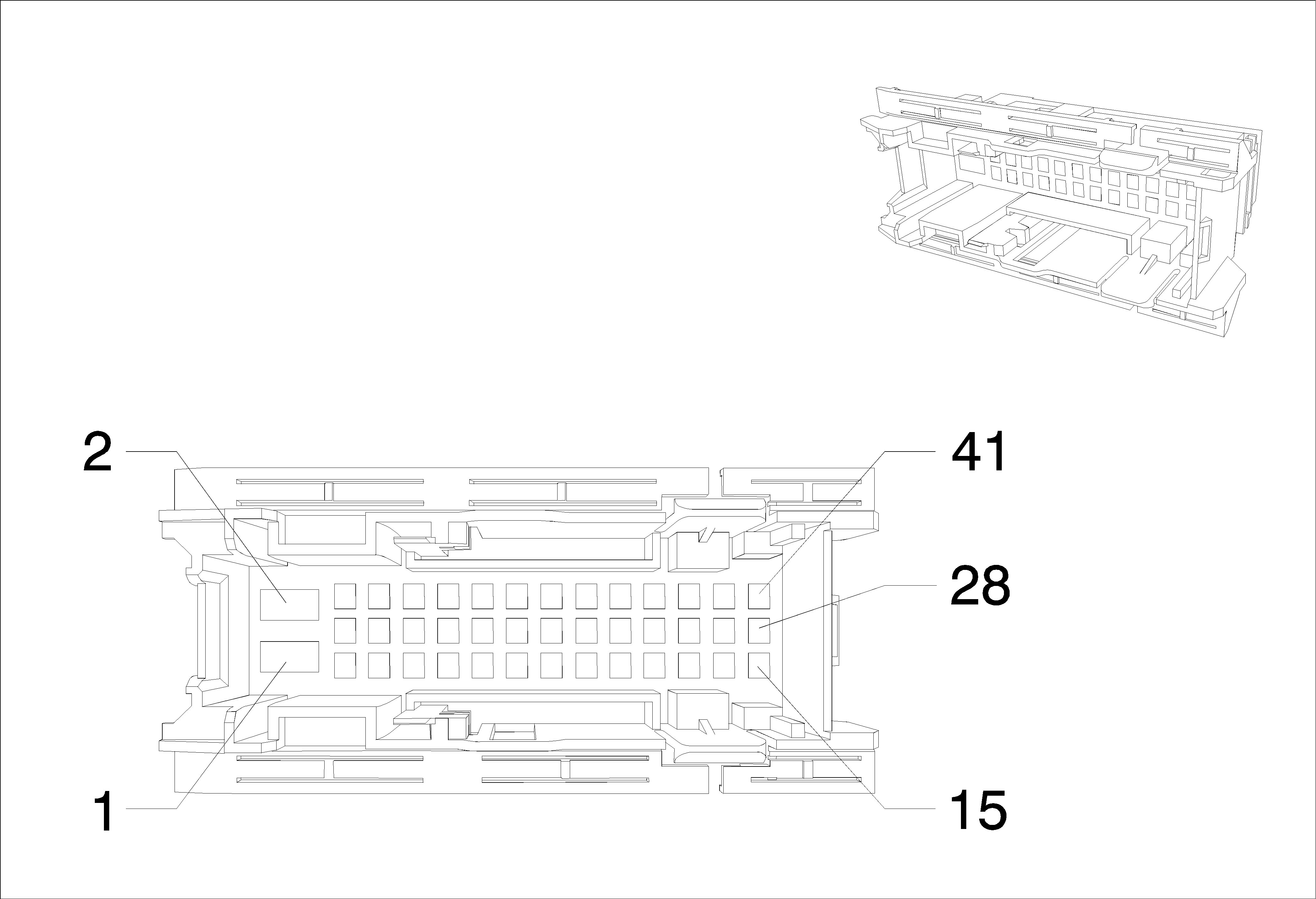
Connector Part Information
|
Terminal Part Information
|
Pin | Wire | Circuit | Function |
|---|---|---|---|
1 | 2.5 Red-Green | 40 | Battery Positive Voltage (AEC) |
2.5 Red-Green | 40 | Battery Positive Voltage (AXG) | |
2.5 Red-Green | 1540 | Battery Positive Voltage | |
2 | 2.5 Black | 50 | Ground |
3 | 1 Black | 50 | Ground |
4 | 0.5 Red-Green | 40 | Battery Positive Voltage |
0.5 Red-Green | 40 | Battery Positive Voltage (AXG) | |
8 | 0.5 Black | 50 | Ground |
9 | 0.75 Gray | 295 | Door Lock Actuator Lock Control ( -AF8) |
0.75 Gray | 295 | Door Lock Actuator Lock Control ( AF8-SAE) | |
10 | 0.75 Brown-Yellow | 294 | Door Lock Actuator Unlock Control ( -AF8) |
0.75 Brown-Yellow | 294 | Door Lock Actuator Unlock Control ( AF8-SAE) | |
11 | 0.75 Brown | 5910 | Door Double Lock Actuator Lock Control ( AF8-SAE) |
12 | 0.5 Black | 50 | Ground |
13 | 0.5 Dark Blue | 6189 | Lift Glass/Trunk Interior Release Signal |
14 | 0.75 Blue | 201 | Left Front Speaker (+) (1) (LHD UQG) |
0.75 Blue | 201 | Left Front Speaker (+) (1) (LHD 6SP UQG) | |
0.75 Blue | 201 | Left Front Speaker (+) (1) (LHD UQG) | |
0.75 Blue | 201 | Left Front Speaker (+) (1) (LHD 6SP UQG) | |
15 | 0.75 Brown-Blue | 118 | Left Front Speaker Signal (-) (1) (LHD UQG) |
0.75 Brown-Blue | 118 | Left Front Speaker Signal (-) (1) (LHD UQG) | |
16 | 0.5 Green-White | 6655 | Driver Door Unlatch Switch Signal |
18 | 0.5 Green-Yellow | 6134 | Linear Interconnect Network Bus 3 |
19 | 0.5 Violet-Yellow | 3409 | Mirror Motor Fold Out Control |
20 | 0.5 White-Brown | 3410 | Mirror Motor Fold In Control |
21 | 0.5 Yellow | 6817 | LED Backlight Dimming Control |
22 | 0.5 Green-Black | 3396 | Co-Driver Mirror Motor Right (+) Left (-) Control |
23 | 0.5 White | 3398 | Co-Driver Mirror Motor Common Control |
24 | 0.5 Yellow-Violet | 3397 | Co-Driver Mirror Motor Up (+) Down (-) Control |
25 | 0.75 Black | 50 | Ground |
26 | - - | - | - |
0.5 Red-Gray | 40 | Battery Positive Voltage | |
27 | 0.5 Gray | 745 | Left Front Door Ajar Switch Signal |
28 | 0.5 Brown-Yellow | 2267 | Mirror Heating Element Control |
31 | 0.5 Green-White | 3570 | Driver Door Handle Switch Signal |
32 | 0.75 Gray | 3578 | Driver Door Unlatch Motor Unlatch Return (ATH) |
33 | 0.5 Violet-Gray | 3561 | Passive Entry Driver Door Antenna Signal Lo |
34 | 0.5 Violet | 3560 | Passive Entry Driver Door Antenna Signal Hi |
40 | 0.5 White-Yellow | 3574 | Driver Door Open Switch Signal (ATH) |
41 | 0.75 Violet-Blue | 6666 | Driver Door Unlatch Motor Unlatch Control (ATH) |
X500 Body Harness & Driver Door Harness (RHD)

Connector Part Information
|
Terminal Part Information
|
Pin | Wire | Circuit | Function |
|---|---|---|---|
1 | 2.5 Red-Green | 40 | Battery Positive Voltage (AEC) |
2.5 Red-Green | 40 | Battery Positive Voltage (AXG) | |
2.5 Red-Green | 1540 | Battery Positive Voltage | |
2 | 2.5 Black | 50 | Ground |
3 | 1 Black | 50 | Ground |
4 | 0.5 Red-Green | 40 | Battery Positive Voltage |
0.5 Red-Green | 40 | Battery Positive Voltage (AXG) | |
8 | 0.5 Black | 50 | Ground |
9 | 0.75 Gray | 295 | Door Lock Actuator Lock Control ( -AF8) |
0.75 Gray | 295 | Door Lock Actuator Lock Control ( AF8-SAE) | |
10 | 0.75 Brown-Yellow | 294 | Door Lock Actuator Unlock Control ( -AF8) |
0.75 Brown-Yellow | 294 | Door Lock Actuator Unlock Control ( AF8-SAE) | |
11 | 0.75 Brown | 5910 | Door Double Lock Actuator Lock Control ( AF8-SAE) |
12 | 0.5 Black | 50 | Ground |
13 | 0.5 Dark Blue | 6189 | Lift Glass/Trunk Interior Release Signal |
14 | 0.75 Yellow | 200 | Right Front Speaker (+) (1) (RHD UQG) |
0.75 Yellow | 200 | Right Front Speaker (+) (1) (RHD 6SP UQG) | |
0.75 Yellow | 200 | Right Front Speaker (+) (1) (RHD UQG) | |
0.75 Yellow | 200 | Right Front Speaker (+) (1) (RHD 6SP UQG) | |
15 | 0.75 Yellow-Black | 117 | Right Front Speaker Signal (-) (1) (RHD UQG) |
0.75 Yellow-Black | 117 | Right Front Speaker Signal (-) (1) (RHD UQG) | |
16 | 0.5 Green-White | 6655 | Driver Door Unlatch Switch Signal |
18 | 0.5 Green-Yellow | 6134 | Linear Interconnect Network Bus 3 |
19 | 0.5 Violet-Yellow | 3409 | Mirror Motor Fold Out Control |
20 | 0.5 White-Brown | 3410 | Mirror Motor Fold In Control |
21 | 0.5 Yellow | 6817 | LED Backlight Dimming Control |
22 | 0.5 Green-Black | 3396 | Co-Driver Mirror Motor Right (+) Left (-) Control |
23 | 0.5 White | 3398 | Co-Driver Mirror Motor Common Control |
24 | 0.5 Yellow-Violet | 3397 | Co-Driver Mirror Motor Up (+) Down (-) Control |
25 | 0.75 Black | 50 | Ground |
26 | - - | - | - |
0.5 Red-Gray | 40 | Battery Positive Voltage | |
27 | 0.5 Gray | 745 | Left Front Door Ajar Switch Signal |
28 | 0.5 Brown-Yellow | 2267 | Mirror Heating Element Control |
31 | 0.5 Green-White | 3570 | Driver Door Handle Switch Signal |
32 | 0.75 Gray | 3578 | Driver Door Unlatch Motor Unlatch Return (ATH) |
33 | 0.5 Violet-Gray | 3561 | Passive Entry Driver Door Antenna Signal Lo |
34 | 0.5 Violet | 3560 | Passive Entry Driver Door Antenna Signal Hi |
40 | 0.5 White-Yellow | 3574 | Driver Door Open Switch Signal (ATH) |
41 | 0.75 Violet-Blue | 6666 | Driver Door Unlatch Motor Unlatch Control (ATH) |
X50A (X1) Fuse Block - Underhood X1
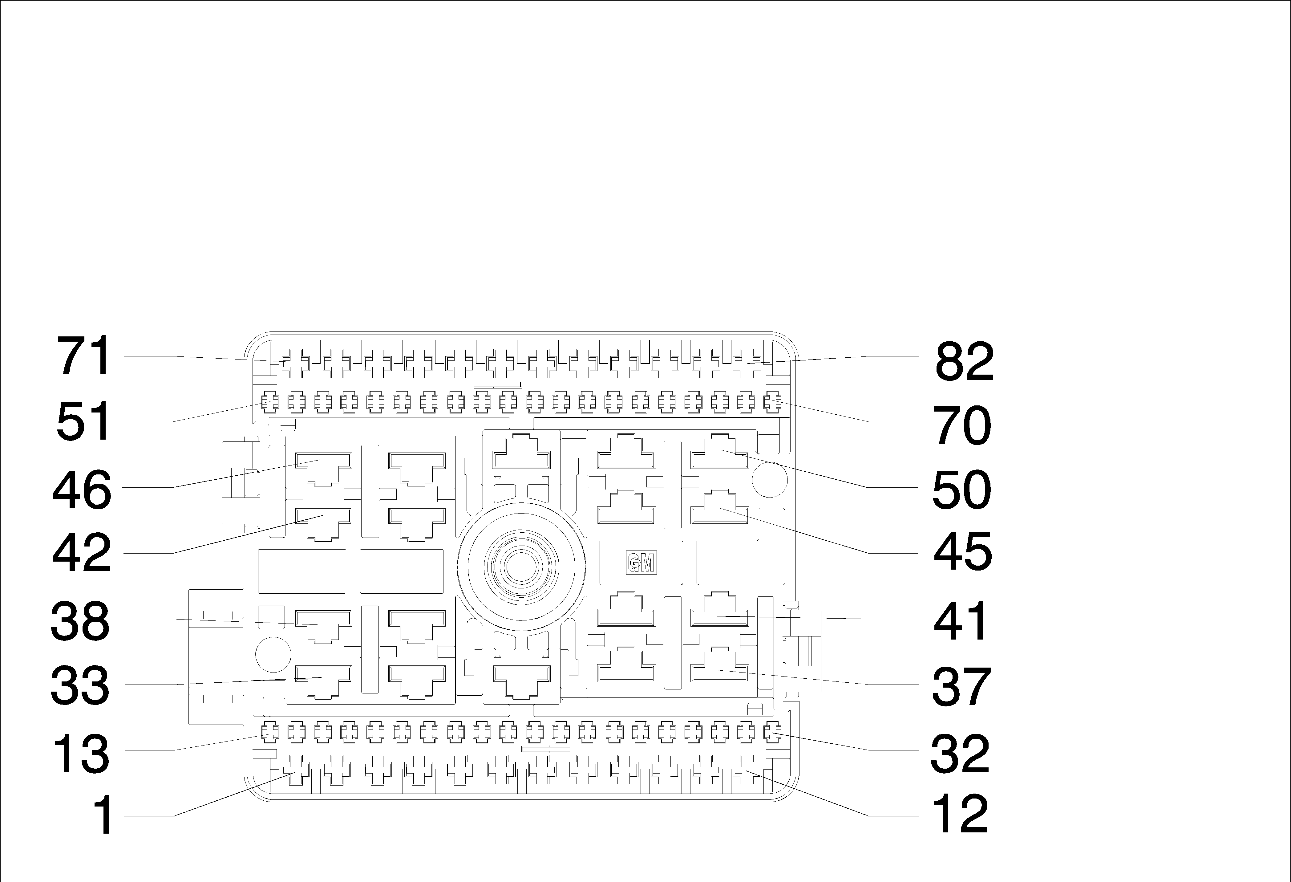
Connector Part Information
|
Terminal Part Information
|
Pin | Wire | Circuit | Function |
|---|---|---|---|
11 | 1 Brown-Gray | 29 | Horn Control |
13 | 1.5 White | 311 | Right Headlamp High Beam Control |
14 | 1.5 White | 711 | Left Headlamp High Beam Control |
20 | 0.5 Red-White | 999 | - (FI) |
0.5 Red-White | 999 | - (LXV LDE 2H0) | |
0.5 Red-White | 999 | - (LXT) | |
21 | 0.5 Violet-Green | 839 | Run/Crank Ignition 1 Voltage (D) |
0.5 Violet-Green | 839 | Run/Crank Ignition 1 Voltage (LLW) | |
30 | 1 Gray-Violet | 228 | Windshield Washer Pump Control |
31 | 0.75 Violet-Brown | 34 | Front Fog Lamp Control |
34 | 0.5 Brown-Yellow | 473 | High Speed Cooling Fan Relay Control (D) |
2.5 Brown-Yellow | 473 | High Speed Cooling Fan Relay Control (LLW) | |
2.5 White-Black | 473 | High Speed Cooling Fan Relay Control (FI) | |
2.5 White-Black | 2366 | Cooling Fan Control Relay Speed Signal (FI) | |
2.5 White-Black | 2366 | Cooling Fan Control Relay Speed Signal (LXV LDE 2H0) | |
2.5 White-Black | 2366 | Cooling Fan Control Relay Speed Signal (LXT) | |
37 | 4 White-Black | 2366 | Cooling Fan Control Relay Speed Signal (LLW) |
43 | 2.5 White-Black | 2366 | Cooling Fan Control Relay Speed Signal (FI) |
2.5 White-Black | 2366 | Cooling Fan Control Relay Speed Signal (LXV LDE 2H0) | |
2.5 White-Black | 2366 | Cooling Fan Control Relay Speed Signal (LXT) | |
2.5 White-Black | 473 | High Speed Cooling Fan Relay Control (FI) | |
46 | 2.5 Gray | 532 | Cooling Fan Motor Control (2) |
2.5 Gray | 532 | Cooling Fan Motor Control (2) (LXV LDE 2H0) | |
2.5 Gray | 532 | Cooling Fan Motor Control (2) (LLW) | |
2.5 Gray | 532 | Cooling Fan Motor Control (2) (LXT) | |
47 | 2.5 White-Blue | 409 | Cooling Fan Motor Control (1) (FI) |
2.5 White-Blue | 409 | Cooling Fan Motor Control (1) (LXV LDE 2H0) | |
2.5 White-Blue | 409 | Cooling Fan Motor Control (1) (LXT) | |
50 | 4 Yellow | 5358 | Cooling Fan Motor Control (3) |
4 Yellow | 5358 | Cooling Fan Motor Control (3) (LXV LDE 2H0) | |
4 Yellow | 5358 | Cooling Fan Motor Control (3) (LLW) | |
4 Yellow | 5358 | Cooling Fan Motor Control (3) (LXT) | |
52 | 0.5 Red-Gray | 1042 | Battery Positive Voltage (LLW) |
53 | 0.5 Brown-Red | 2700 | A/C Pressure Sensor 5 Volt Reference (LDE/LXV/2H0) |
0.5 Brown-Red | 2700 | A/C Pressure Sensor 5 Volt Reference (LLW) | |
0.5 Brown-Red | 2700 | A/C Pressure Sensor 5 Volt Reference (LXT) | |
54 | 0.5 Black-Blue | 6813 | Coolant Temperature Sensor #2 Low Reference (LDE/LXV/2H0) |
55 | 0.5 Black-Brown | 5514 | A/C Refrigerant Pressure Sensor Low Reference (LDE/LXV/2H0) |
0.5 Black-Brown | 5514 | A/C Refrigerant Pressure Sensor Low Reference (LLW) | |
0.5 Black-Brown | 5514 | A/C Refrigerant Pressure Sensor Low Reference (LXT) | |
56 | 0.5 Green-Violet | 2032 | Coolant Temperature Sensor Signal (LDE/LXV/2H0) |
57 | 0.5 Green | 380 | A/C Refrigerant Pressure Sensor Signal (LDE/LXV/2H0) |
0.5 Green | 380 | A/C Refrigerant Pressure Sensor Signal (LLW) | |
0.5 Green | 380 | A/C Refrigerant Pressure Sensor Signal (LXT) | |
65 | 0.5 Violet-Green | 1339 | Run/Crank Ignition 1 Voltage |
0.5 Violet-Green | 39 | Ignition Voltage | |
66 | 0.5 Red-White | 999 | - (FI) |
0.5 Red-White | 999 | - (LXV LDE 2H0) | |
0.5 Red-White | 999 | - (LXT) | |
0.5 Violet-Green | 839 | Run/Crank Ignition 1 Voltage (LLW) | |
0.5 Violet-Green | 839 | Run/Crank Ignition 1 Voltage (D) | |
67 | 0.5 Green | 7625 | Cooling Fan Motor Supply Voltage (4) |
0.5 Green | 7625 | Cooling Fan Motor Supply Voltage (4) (LXV LDE 2H0) | |
0.5 Green | 7625 | Cooling Fan Motor Supply Voltage (4) (LLW) | |
0.5 Green | 7625 | Cooling Fan Motor Supply Voltage (4) (LXT) | |
68 | 0.5 Green | 7625 | Cooling Fan Motor Supply Voltage (4) (LXV LDE 2H0) |
0.5 Green | 7625 | Cooling Fan Motor Supply Voltage (4) (LLW) | |
0.5 Green | 7625 | Cooling Fan Motor Supply Voltage (4) (LXT) | |
- - | - | - | |
71 | 2.5 Black | 50 | Ground |
72 | 2.5 White | 92 | Windshield Wiper Motor High Speed Control |
73 | 2.5 Yellow-Brown | 95 | Windshield Wiper Motor Low Speed Control |
74 | 2.5 Black | 50 | Ground |
X50A (X2) Fuse Block - Underhood X2

Connector Part Information
|
Terminal Part Information
|
Pin | Wire | Circuit | Function |
|---|---|---|---|
4 | 0.75 Gray | 295 | Door Lock Actuator Lock Control (-AF8 SAE) |
5 | 0.75 White-Blue | 3266 | Child Security Lock Motor Unlock Control (-AF8 SAE) |
6 | 2.5 Gray | 120 | Fuel Pump Control |
2.5 Gray | 120 | Fuel Pump Control (LDE/LXV/2H0) | |
2.5 Gray | 120 | Fuel Pump Control (LLW -SAE) | |
2.5 Gray | 120 | Fuel Pump Control (LXT -SAE) | |
10 | 0.75 Brown-Green | 59 | A/C Compressor Clutch Control (LXT) |
0.5 Brown-Green | 59 | A/C Compressor Clutch Control (LXT) | |
12 | 0.75 Gray-Green | 3271 | Door Lock Control (2) ( -AF8 SAE) |
13 | 0.75 Violet-Yellow | 3267 | Child Security Lock Relay Control (-AF8 SAE) |
14 | 0.5 Violet-Green | 39 | Ignition Voltage |
0.5 Violet-Green | 3039 | Run/Crank Ignition 1 Voltage | |
15 | 0.5 Violet-Pink | 39 | Ignition Voltage (SAE LDE OR LXV OR 2H0) |
0.5 Violet-Black | 739 | Run/Crank Ignition 1 Voltage (LLW SAE) | |
0.5 Violet-Black | 739 | Run/Crank Ignition 1 Voltage | |
0.5 Violet-Black | 39 | Ignition Voltage (LXT SAE) | |
16 | 0.5 Violet-Blue | 5290 | Powertrain Main Relay Fused Supply (1) (LLW) |
0.5 Violet-Blue | 5290 | Powertrain Main Relay Fused Supply (1) (LLW) | |
17 | 0.5 Brown-White | 5069 | Engine Main Relay Coil Control (LLW) |
0.5 Brown-Violet | 1594 | Ignition 3 Relay Control | |
0.5 Brown-Violet | 1594 | Ignition 3 Relay Control (ATH) | |
0.5 Brown-Violet | 1594 | Ignition 3 Relay Control (-ATH) | |
19 | 0.5 Brown-White | 1317 | Fog Lamp Relay Control |
21 | 0.5 Blue-Brown | 7573 | Electric Variable Displacement Supply |
0.5 Blue-Brown | 7573 | Electric Variable Displacement Supply (LDE/LXV/2H0) | |
0.5 Blue-Brown | 7573 | Electric Variable Displacement Supply (LLW) | |
0.5 Blue-Brown | 7573 | Electric Variable Displacement Supply (LXT) | |
22 | 0.5 Gray | 91 | Windshield Wiper Motor Relay Coil Control |
23 | 0.5 Red-Gray | 40 | Battery Positive Voltage |
25 | 0.5 Brown-White | 28 | Horn Relay Control |
26 | 0.5 Violet-White | 239 | Ignition Voltage |
28 | 0.5 Red-Gray | 40 | Battery Positive Voltage |
0.5 Red-Green | 40 | Battery Positive Voltage (AXG) | |
0.5 Red-Green | 40 | Battery Positive Voltage | |
29 | 0.5 Violet-White | 39 | Ignition Voltage |
0.5 Violet-White | 239 | Ignition Voltage | |
31 | 0.5 Violet-White | 39 | Ignition Voltage |
-- | -- | -- | |
32 | 1 Blue-Violet | 807 | OFF /Accessory Voltage |
1 Blue-Violet | 807 | OFF /Accessory Voltage (-ATH) | |
33 | 4 Red-Brown | 40 | Battery Positive Voltage |
4 Red-Brown | 40 | Battery Positive Voltage (AEQ) | |
36 | 4 Red-Green | 1540 | Battery Positive Voltage |
4.0 Red-Green | 40 | Battery Positive Voltage | |
4 Red-Green | 40 | Battery Positive Voltage (AEC) | |
2.5 Red-Green | 40 | Battery Positive Voltage (AXG) | |
37 | 2.5 Red-Blue | 1842 | Battery Positive Voltage |
2.5 Red-Blue | 1842 | Battery Positive Voltage (LLW) | |
39 | 4 Brown-Violet | 293 | Rear Defog Element Control |
40 | 2.5 Red-Violet | 40 | Battery Positive Voltage |
41 | 4 Red-Violet | 40 | Battery Positive Voltage |
42 | 4 Red-Green | 40 | Battery Positive Voltage |
4 Red-Green | 40 | Battery Positive Voltage (ATH) | |
45 | 0.5 White-Violet | 860 | Front Windshield Wiper Switch High Signal |
48 | 0.5 Blue-Brown | 7547 | Security Lock Relay Control (AF8-SAE) |
49 | 0.5 Brown-Blue | 1977 | Rear Fog Lamp Relay Control |
50 | 0.75 Gray | 295 | Door Lock Actuator Lock Control (AF8 AF8-SAE) |
51 | 0.5 Yellow-Gray | 122 | Rear Fog Lamp Control |
52 | 0.75 Blue-White | 195 | Door Lock Control (AF8 AF8-SAE) |
53 | 0.75 Brown | 5910 | Door Double Lock Actuator Lock Control (AF8-SAE) |
56 | 1 Red-Green | 40 | Battery Positive Voltage |
1.5 Red-Green | 1840 | Battery Positive Voltage | |
58 | 0.5 Brown-Violet | 1969 | Headlamp High Beam Relay Control |
60 | 0.5 Brown-Gray | 2268 | Windshield Washer Relay Control |
61 | 0.5 Brown-Violet | 193 | Rear Defog Relay Control |
62 | 0.5 Brown-Yellow | 2267 | Mirror Heating Element Control |
63 | 0.5 Red-Gray | 402 | Battery Positive Voltage |
0.5 Red-Gray | 402 | Battery Positive Voltage (AL0) | |
64 | 0.5 Red-White | 40 | Battery Positive Voltage |
67 | 1.5 Red-White | 40 | Battery Positive Voltage |
68 | 1.5 Red-Violet | 40 | Battery Positive Voltage |
69 | 2.5 Red-White | 40 | Battery Positive Voltage |
2.5 Red-Green | 40 | Battery Positive Voltage | |
70 | 2.5 Red-White | 40 | Battery Positive Voltage |
71 | 2.5 Red-White | 40 | Battery Positive Voltage |
2.5 Red-White | 40 | Battery Positive Voltage (UQG) | |
72 | 0.5 Red-Brown | 40 | Battery Positive Voltage |
73 | 0.5 Blue-Brown | 7573 | Electric Variable Displacement Supply |
0.5 Blue-Brown | 7573 | Electric Variable Displacement Supply (LDE/LXV/2H0) | |
0.5 Blue-Brown | 7573 | Electric Variable Displacement Supply (LLW) | |
0.5 Blue-Brown | 7573 | Electric Variable Displacement Supply (LXT) | |
74 | 2.5 Red-Gray | 40 | Battery Positive Voltage |
2.5 Red-Gray | 40 | Battery Positive Voltage (SAE LDE OR LXV OR 2H0) | |
2.5 Red-Gray | 40 | Battery Positive Voltage (LLW SAE) | |
2.5 Red-Gray | 40 | Battery Positive Voltage (LXT SAE) |
X50D Fuse Block - Battery X6
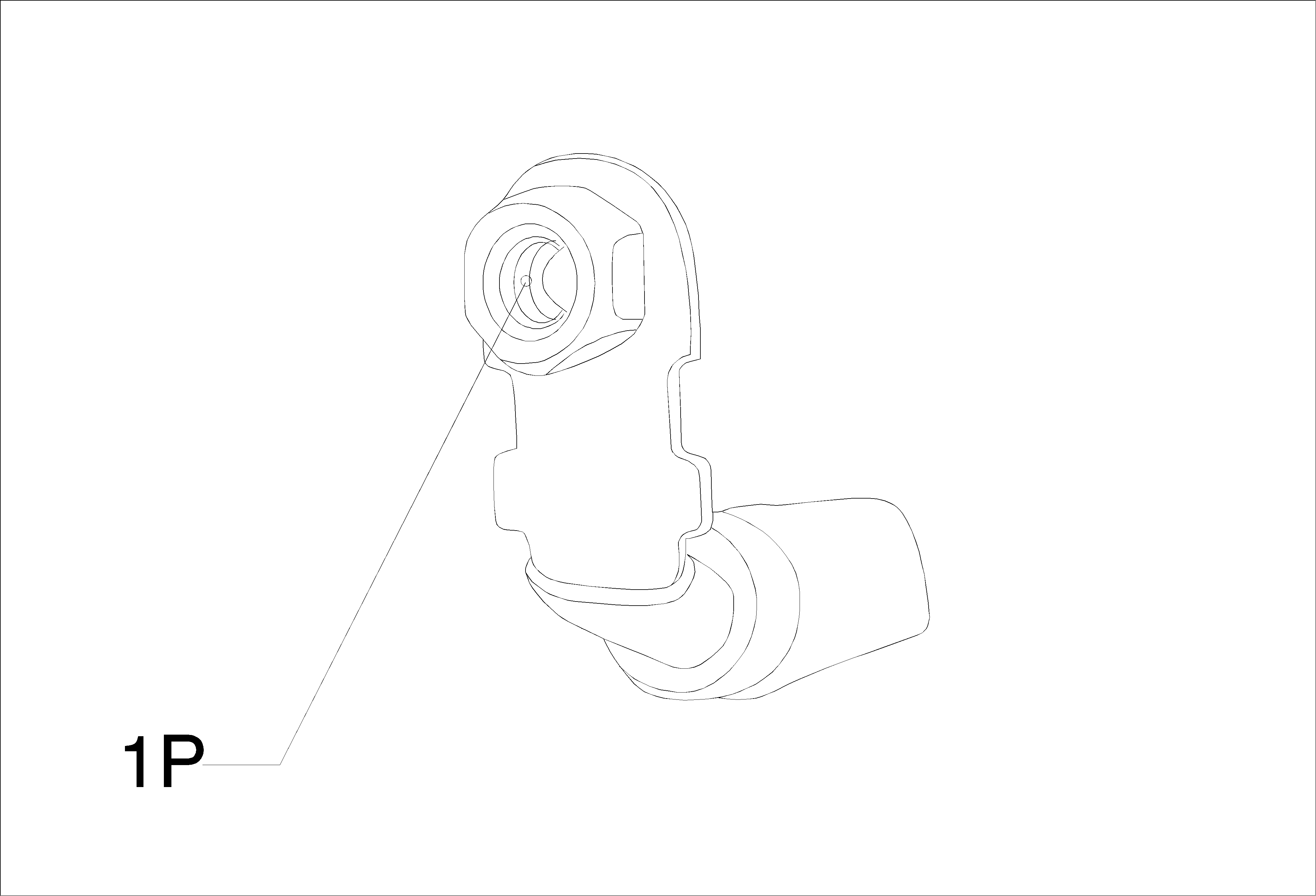
Connector Part Information
|
Terminal Part Information
|
Pin | Wire | Circuit | Function |
|---|---|---|---|
X600 Body Harness & Passenger Door Harness

Connector Part Information
|
Terminal Part Information
|
Pin | Wire | Circuit | Function |
|---|---|---|---|
1 | 2.5 Red-Green | 40 | Battery Positive Voltage |
2.5 Red-Green | 1540 | Battery Positive Voltage | |
2 | 2.5 Black | 50 | Ground |
3 | 1 Black | 50 | Ground |
5 | 0.75 Brown-Yellow | 294 | Door Lock Actuator Unlock Control ( -AF8) |
0.75 Brown-Yellow | 294 | Door Lock Actuator Unlock Control ( AF8-SAE) | |
8 | 0.5 Black | 50 | Ground |
2 Black | 50 | Ground | |
9 | 0.75 Gray | 295 | Door Lock Actuator Lock Control ( -AF8) |
0.75 Gray | 295 | Door Lock Actuator Lock Control ( AF8-SAE) | |
10 | 0.75 Brown | 5910 | Door Double Lock Actuator Lock Control ( AF8-SAE) |
11 | 0.5 Yellow-Violet | 3397 | Co-Driver Mirror Motor Up (+) Down (-) Control |
13 | 0.5 Green-Black | 3396 | Co-Driver Mirror Motor Right (+) Left (-) Control |
14 | 0.5 White | 3398 | Co-Driver Mirror Motor Common Control |
15 | 0.5 Green-Yellow | 6134 | Linear Interconnect Network Bus 3 |
16 | 0.75 Gray-Blue | 3576 | Co-Driver Door Exterior Switch Lock Signal |
17 | 0.75 Yellow-Black | 117 | Right Front Speaker Signal (-) (1) (LHD UQG) |
0.75 Yellow-Black | 117 | Right Front Speaker Signal (-) (1) (LHD UQG) | |
0.75 Brown-Blue | 118 | Left Front Speaker Signal (-) (1) (RHD UQG) | |
0.75 Brown-Blue | 118 | Left Front Speaker Signal (-) (1) (RHD UQG) | |
18 | 0.75 Blue | 201 | Left Front Speaker (+) (1) (RHD UQG) |
0.75 Blue | 201 | Left Front Speaker (+) (1) (RHD UQG) | |
0.75 Yellow | 200 | Right Front Speaker (+) (1) (LHD UQG) | |
0.75 Yellow | 200 | Right Front Speaker (+) (1) (LHD UQG) | |
21 | 0.5 White-Brown | 3410 | Mirror Motor Fold In Control |
22 | 0.5 Violet-Yellow | 3409 | Mirror Motor Fold Out Control |
23 | 0.5 Brown-Yellow | 2267 | Mirror Heating Element Control |
27 | 0.5 Gray | 746 | Right Front Door Ajar Switch Signal (-AED) |
31 | 0.5 Violet-White | 3571 | Co_Driver Door Handle Switch Signal |
32 | 0.75 Gray-Black | 3579 | Co Driver Door Unlatch Motor Unlatch Return (ATH) |
33 | 0.5 Green-Black | 3563 | Passive Entry Co_Driver Door Antenna Signal Lo |
34 | 0.5 Green-Yellow | 3562 | Passive Entry Co_Driver Door Antenna Signal Hi |
40 | 0.5 Gray-Green | 3575 | Co_Driver Door Open Switch Signal (ATH) |
41 | 0.75 Yellow-Green | 3583 | Co Driver Door Unlatch Motor Unlatch Control (ATH) |
X600 Body Harness & Passenger Door Harness (LHD)

Connector Part Information
|
Terminal Part Information
|
Pin | Wire | Circuit | Function |
|---|---|---|---|
1 | 2.5 Red-Green | 40 | Battery Positive Voltage |
2.5 Red-Green | 1540 | Battery Positive Voltage | |
2 | 2 Black | 50 | Ground |
3 | 1 Black | 50 | Ground |
5 | 0.75 Brown-Yellow | 294 | Door Lock Actuator Unlock Control ( -AF8) |
0.75 Brown-Yellow | 294 | Door Lock Actuator Unlock Control ( AF8-SAE) | |
8 | 1 Black | 50 | Ground |
9 | 0.75 Gray | 295 | Door Lock Actuator Lock Control ( -AF8) |
0.75 Gray | 295 | Door Lock Actuator Lock Control ( AF8-SAE) | |
10 | 0.75 Brown | 5910 | Door Double Lock Actuator Lock Control ( AF8-SAE) |
11 | 0.5 Yellow-Violet | 3397 | Co-Driver Mirror Motor Up (+) Down (-) Control |
13 | 0.5 Green-Black | 3396 | Co-Driver Mirror Motor Right (+) Left (-) Control |
14 | 0.5 White | 3398 | Co-Driver Mirror Motor Common Control |
15 | 0.5 Green-Yellow | 6134 | Linear Interconnect Network Bus 3 |
16 | 0.75 Gray-Blue | 3576 | Co-Driver Door Exterior Switch Lock Signal |
17 | 0.75 Yellow-Black | 117 | Right Front Speaker Signal (-) (1) (LHD UQG) |
0.75 Yellow-Black | 117 | Right Front Speaker Signal (-) (1) (LHD UQG) | |
18 | 0.75 Yellow | 200 | Right Front Speaker (+) (1) (LHD UQG) |
0.75 Yellow | 200 | Right Front Speaker (+) (1) (LHD 6SP UQG) | |
0.75 Yellow | 200 | Right Front Speaker (+) (1) (LHD UQG) | |
0.75 Yellow | 200 | Right Front Speaker (+) (1) (LHD 6SP UQG) | |
21 | 0.5 White-Brown | 3410 | Mirror Motor Fold In Control |
22 | 0.5 Violet-Yellow | 3409 | Mirror Motor Fold Out Control |
23 | 0.5 Brown-Yellow | 2267 | Mirror Heating Element Control |
27 | 0.5 Gray | 746 | Right Front Door Ajar Switch Signal |
31 | 0.5 Violet-White | 3571 | Co_Driver Door Handle Switch Signal |
32 | 0.75 Gray-Black | 3579 | Co Driver Door Unlatch Motor Unlatch Return (ATH) |
33 | 0.5 Green-Black | 3563 | Passive Entry Co_Driver Door Antenna Signal Lo |
34 | 0.5 Green-Yellow | 3562 | Passive Entry Co_Driver Door Antenna Signal Hi |
40 | 0.5 Gray-Green | 3575 | Co_Driver Door Open Switch Signal (ATH) |
41 | 0.75 Yellow-Green | 3583 | Co Driver Door Unlatch Motor Unlatch Control (ATH) |
X600 Body Harness & Passenger Door Harness (RHD)

Connector Part Information
|
Terminal Part Information
|
Pin | Wire | Circuit | Function |
|---|---|---|---|
1 | 2.5 Red-Green | 40 | Battery Positive Voltage |
2.5 Red-Green | 1540 | Battery Positive Voltage | |
2 | 2 Black | 50 | Ground |
3 | 1 Black | 50 | Ground |
5 | 0.75 Brown-Yellow | 294 | Door Lock Actuator Unlock Control ( -AF8) |
0.75 Brown-Yellow | 294 | Door Lock Actuator Unlock Control ( AF8-SAE) | |
8 | 1 Black | 50 | Ground |
9 | 0.75 Gray | 295 | Door Lock Actuator Lock Control ( -AF8) |
0.75 Gray | 295 | Door Lock Actuator Lock Control ( AF8-SAE) | |
10 | 0.75 Brown | 5910 | Door Double Lock Actuator Lock Control ( AF8-SAE) |
11 | 0.5 Yellow-Violet | 3397 | Co-Driver Mirror Motor Up (+) Down (-) Control |
13 | 0.5 Green-Black | 3396 | Co-Driver Mirror Motor Right (+) Left (-) Control |
14 | 0.5 White | 3398 | Co-Driver Mirror Motor Common Control |
15 | 0.5 Green-Yellow | 6134 | Linear Interconnect Network Bus 3 |
16 | 0.75 Gray-Blue | 3576 | Co-Driver Door Exterior Switch Lock Signal |
17 | 0.75 Brown-Blue | 118 | Left Front Speaker Signal (-) (1) (RHD UQG) |
0.75 Brown-Blue | 118 | Left Front Speaker Signal (-) (1) (RHD UQG) | |
18 | 0.75 Blue | 201 | Left Front Speaker (+) (1) (RHD UQG) |
0.75 Blue | 201 | Left Front Speaker (+) (1) (RHD 6SP UQG) | |
0.75 Blue | 201 | Left Front Speaker (+) (1) (RHD UQG) | |
0.75 Blue | 201 | Left Front Speaker (+) (1) (RHD 6SP UQG) | |
21 | 0.5 White-Brown | 3410 | Mirror Motor Fold In Control |
22 | 0.5 Violet-Yellow | 3409 | Mirror Motor Fold Out Control |
23 | 0.5 Brown-Yellow | 2267 | Mirror Heating Element Control |
27 | 0.5 Gray | 746 | Right Front Door Ajar Switch Signal |
31 | 0.5 Violet-White | 3571 | Co_Driver Door Handle Switch Signal |
32 | 0.75 Gray-Black | 3579 | Co Driver Door Unlatch Motor Unlatch Return (ATH) |
33 | 0.5 Green-Black | 3563 | Passive Entry Co_Driver Door Antenna Signal Lo |
34 | 0.5 Green-Yellow | 3562 | Passive Entry Co_Driver Door Antenna Signal Hi |
40 | 0.5 Gray-Green | 3575 | Co_Driver Door Open Switch Signal (ATH) |
41 | 0.75 Yellow-Green | 3583 | Co Driver Door Unlatch Motor Unlatch Control (ATH) |
X70 Relay Block - Underhood X3

Connector Part Information
|
Terminal Part Information
|
Pin | Wire | Circuit | Function |
|---|---|---|---|
2 | 4 Black | 50 | Ground (LLW) |
4 | 0.5 Violet-Green | 839 | Run/Crank Ignition 1 Voltage |
0.5 Violet-Green | 839 | Run/Crank Ignition 1 Voltage (LLW) | |
5 | 4 Black | 50 | Ground |
4 Blue-Violet | 2364 | Cooling Fan Speed Signal (LLW) | |
6 | 0.5 Red-Gray | 1042 | Battery Positive Voltage (LLW) |
8 | 4 Black | 50 | Ground (LLW) |
X84 Data Link Connector

Connector Part Information
|
Terminal Part Information
|
Pin | Wire | Circuit | Function |
|---|---|---|---|
1 | 0.5 Green | 5060 | Low Speed GMLAN Serial Data |
4 | 0.5 Black | 50 | Ground |
5 | 0.5 Black | 50 | Ground |
6 | 0.5 Blue | 2500 | High Speed GMLAN Serial Data (+) (1) |
7 | 0.5 Brown-White | 5043 | Keyword 2000 Serial Data |
12 | 0.5 Blue-Yellow | 6105 | High Speed GMLAN Serial Data (+) (2) |
13 | 0.5 White | 6106 | High Speed GMLAN Serial Data (-) (2) |
14 | 0.5 White | 2501 | High Speed GMLAN Serial Data (-) (1) |
16 | 0.5 Red-Blue | 40 | Battery Positive Voltage |
0.5 Red-Blue | 840 | Battery Positive Voltage |
X85 Steering Wheel Air Bag Coil X1

Connector Part Information
|
Terminal Part Information
|
Pin | Wire | Circuit | Function |
|---|---|---|---|
1 | 0.5 Green-White | 3287 | Horn Switch Signal |
2 | 0.5 Black | 50 | Ground |
3 | 0.5 Gray-Green | 5737 | Adaptive Cruise Control Gap Up/Down Switch Signal |
4 | 0.5 Green-White | 6819 | Steering Wheel Resistor Ladder Signal #2 |
5 | 0.5 White-Red | 1444 | 12 Volt Reference |
6 | 0.5 Yellow | 6817 | LED Backlight Dimming Control |
X85 Steering Wheel Air Bag Coil X2

Connector Part Information
|
Terminal Part Information
|
Pin | Wire | Circuit | Function |
|---|---|---|---|
1 | 0.5 Orange-Violet | 3021 | Steering Wheel Module Stage 1 High Control |
2 | 0.5 Brown-Orange | 3020 | Steering Wheel Module Stage 1 Low Control |
3 | 0.5 Orange-Green | 3023 | Steering Wheel Module Stage 2 High Control |
4 | 0.5 White-Orange | 3022 | Steering Wheel Module Stage 2 Low Control |
X85 (X3) Steering Wheel Air Bag Coil X3 (Female)

Connector Part Information
|
Terminal Part Information
|
Pin | Wire | Circuit | Function |
|---|---|---|---|
X900 Body Harness & Liftgate Harness
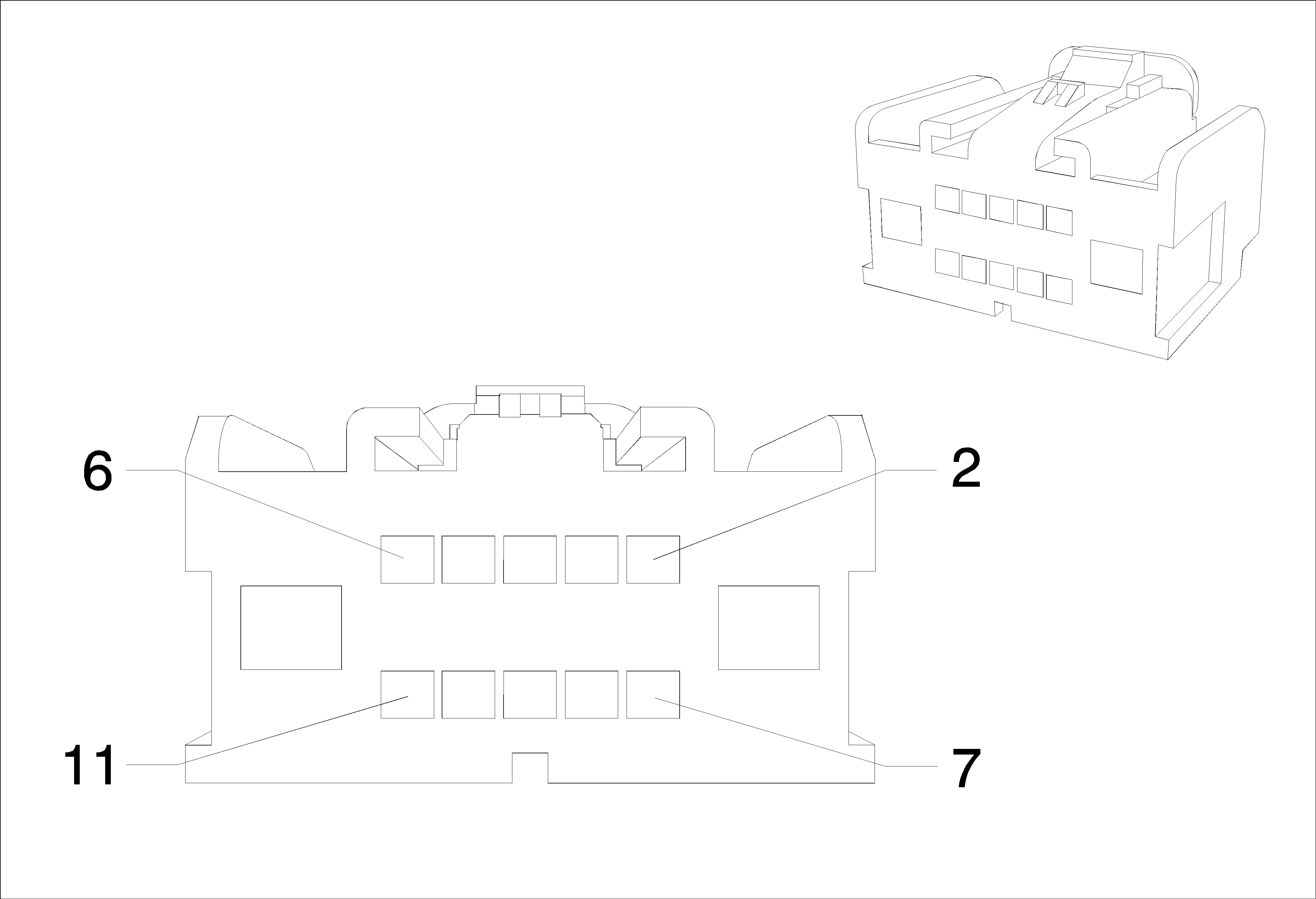
Connector Part Information
|
Terminal Part Information
|
Pin | Wire | Circuit | Function |
|---|---|---|---|
1 | 0.5 Blue-Yellow | 6795 | Lift Glass/Trunk Motor Release Control 2 |
2 | 0.5 Violet-Gray | 1303 | Lift Gate Ajar Switch Signal (1) |
4 | 0.5 Green-Yellow | 6846 | Rear License Lamp Control |
5 | 0.5 Yellow-Gray | 122 | Rear Fog Lamp Control |
6 | 0.5 Black | 50 | Ground |
10 | 0.5 Violet-Gray | 709 | Left Park Lamp Control (DOM) |
0.5 Violet-Gray | 709 | Left Park Lamp Control (SAE) | |
11 | 0.5 Gray-Brown | 309 | Right Park Lamp Control (DOM) |
0.5 Gray-Brown | 309 | Right Park Lamp Control (SAE) | |
12 | 0.5 Black | 50 | Ground |
X900 Body Harness & Liftgate Harness (Male)
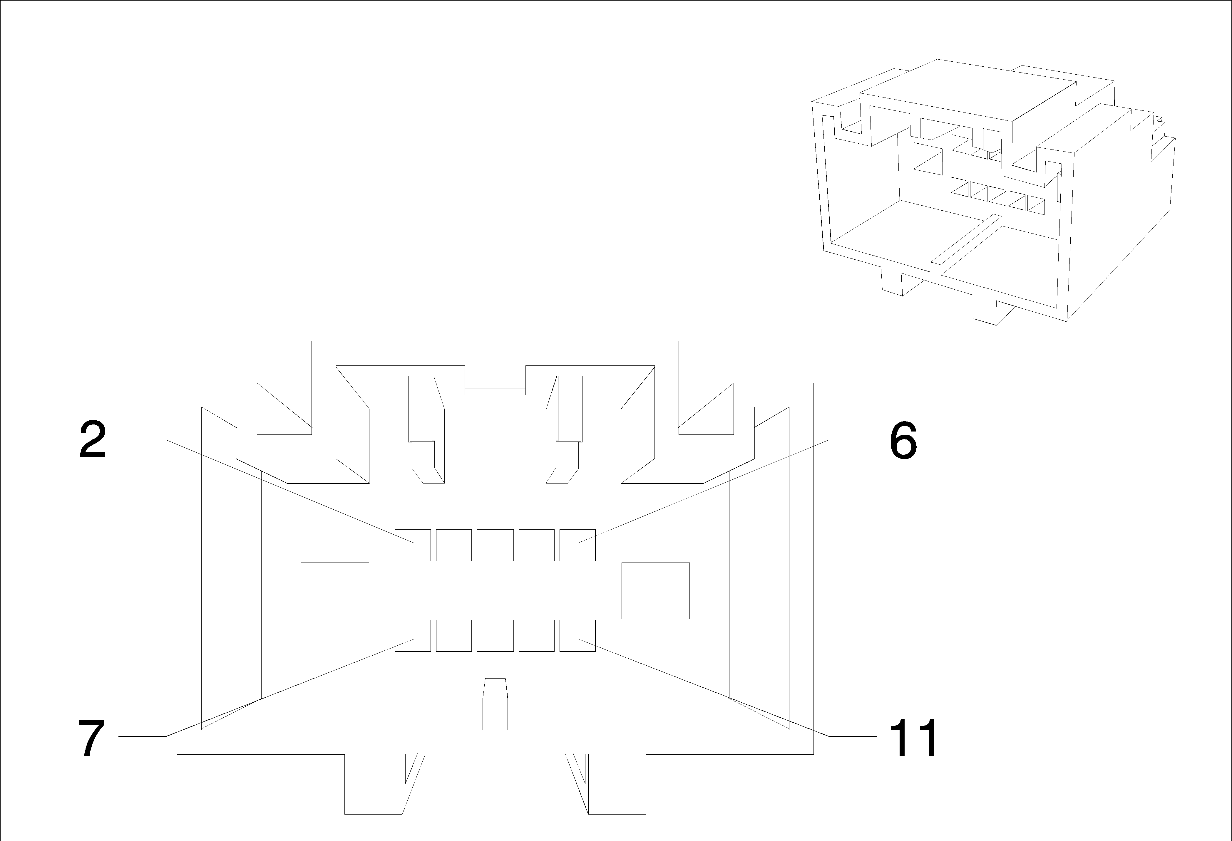
Connector Part Information
|
Terminal Part Information
|
Pin | Wire | Circuit | Function |
|---|---|---|---|
X912 Body Harness & Tail Lamp Left Harness (Male) (SAE)
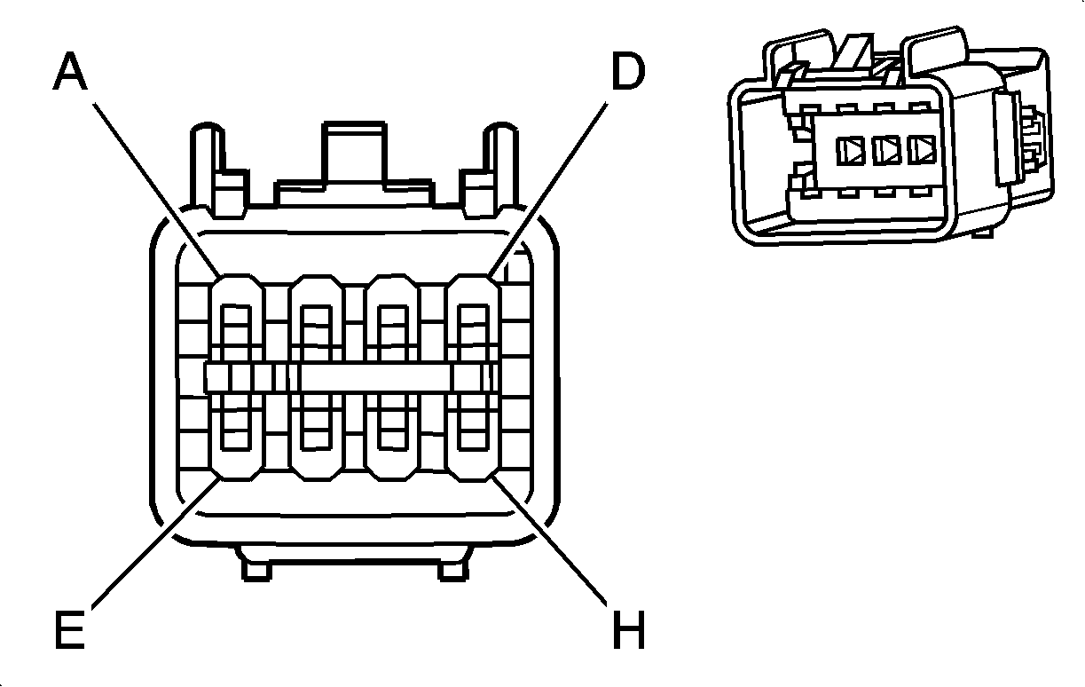
Connector Part Information
|
Terminal Part Information
|
Pin | Wire | Circuit | Function |
|---|---|---|---|
X913 Body Harness & Tail Lamp Right Harness (Male) (SAE)

Connector Part Information
|
Terminal Part Information
|
Pin | Wire | Circuit | Function |
|---|---|---|---|
X914 Liftgate Harness & Liftgate Tail Lamp Left Harness (Female) (DOM)
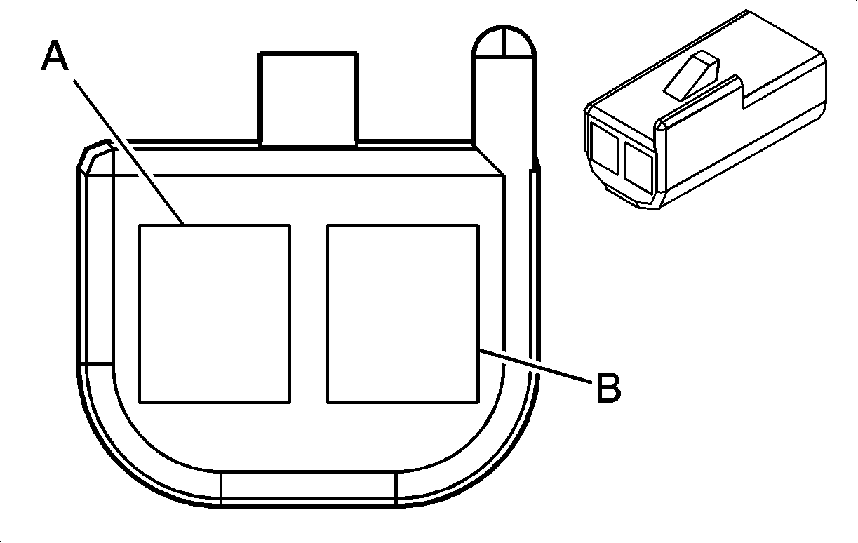
Connector Part Information
|
Terminal Part Information
|
Pin | Wire | Circuit | Function |
|---|---|---|---|
X915 Liftgate Harness & Liftgate Tail Lamp Left Harness (Male) (SAE)
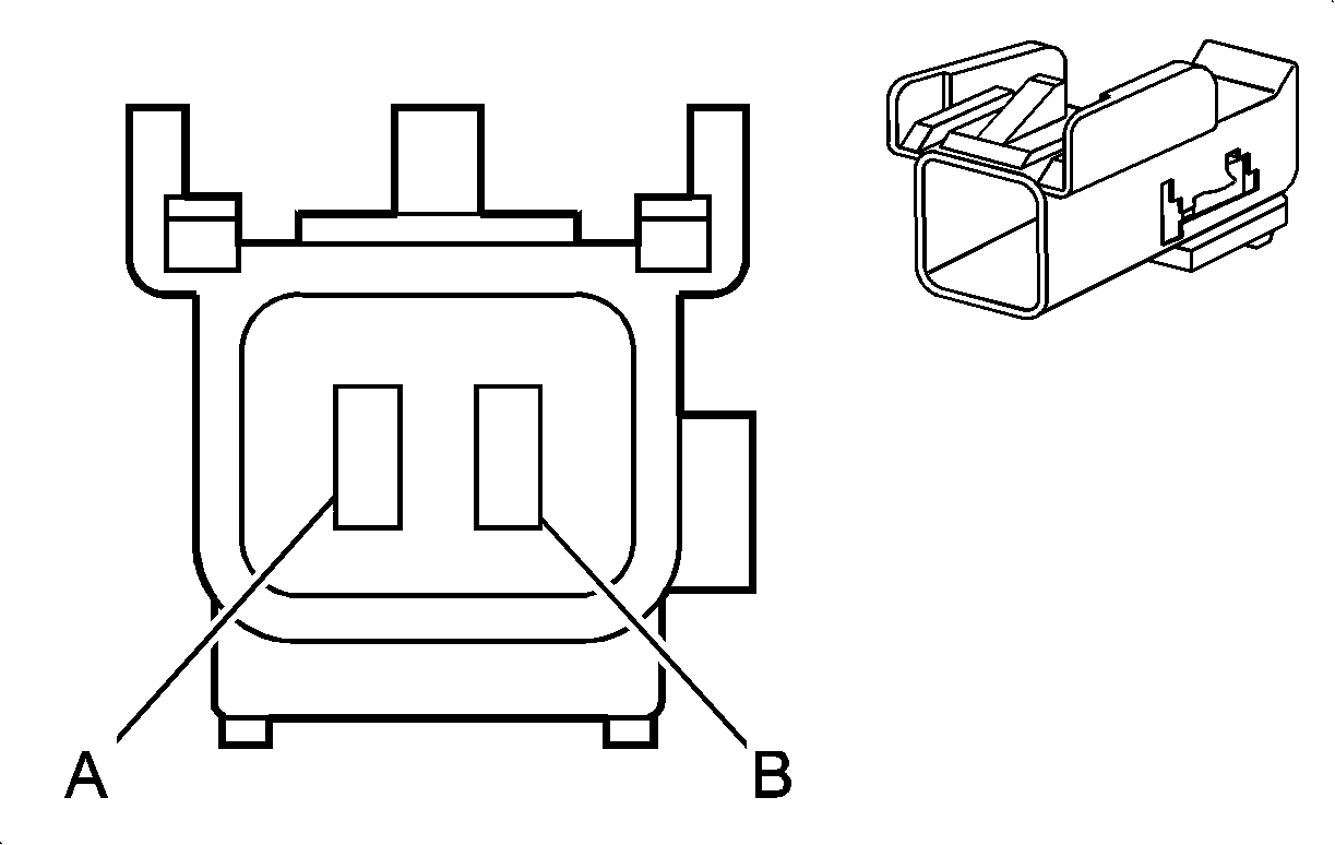
Connector Part Information
|
Terminal Part Information
|
Pin | Wire | Circuit | Function |
|---|---|---|---|
X917 Liftgate Harness & Liftgate Tail Lamp Right Harness (Male) (SAE)

Connector Part Information
|
Terminal Part Information
|
Pin | Wire | Circuit | Function |
|---|---|---|---|
X92 (X1) Universal Serial Bus (USB) Connector X1 (Female)
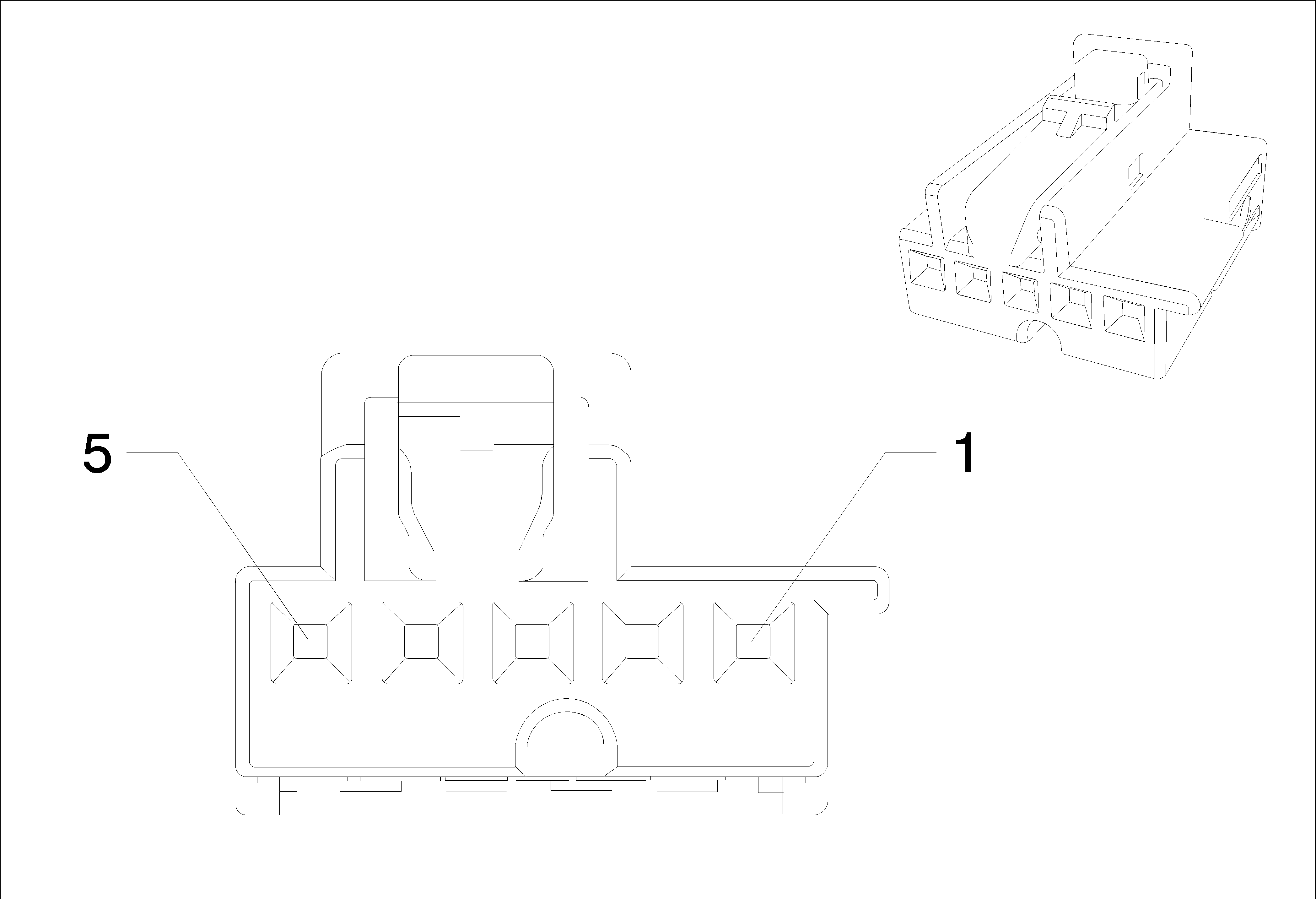
Connector Part Information
|
Terminal Part Information
|
Pin | Wire | Circuit | Function |
|---|---|---|---|
