For 1990-2009 cars only
Removal Procedure
- Remove instrument panel compartment assembly. Refer to Instrument Panel Compartment Replacement.
- Remove instrument panel wiring harness (2) from instrument panel tie bar (1).
- Remove instrument panel tie bar (2).
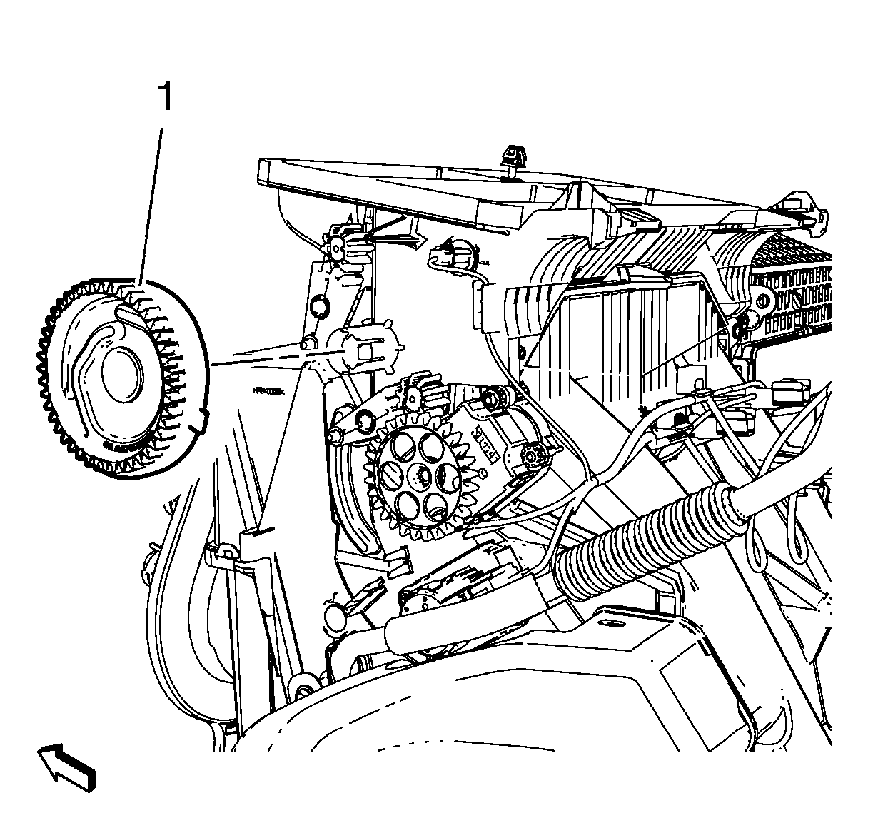
- Remove mode control cam (1).
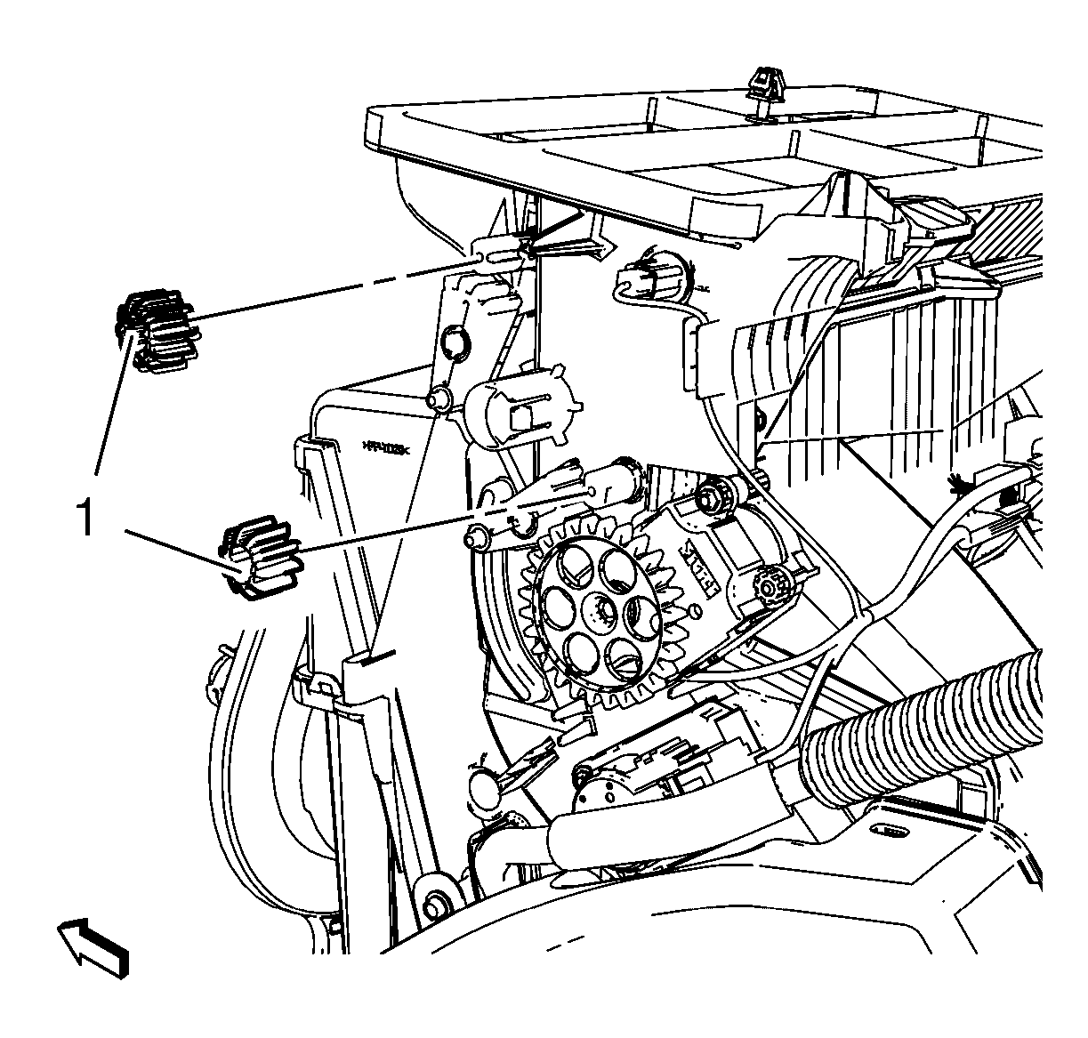
- Remove 2 mode valve gear (1).
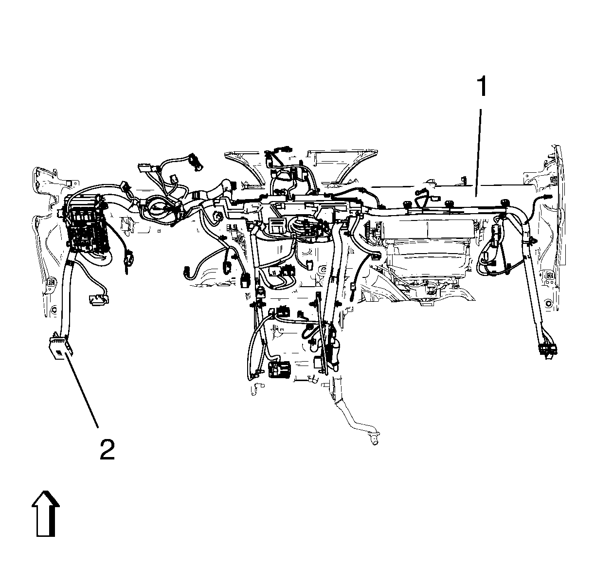
Disconnect electrical connectors.
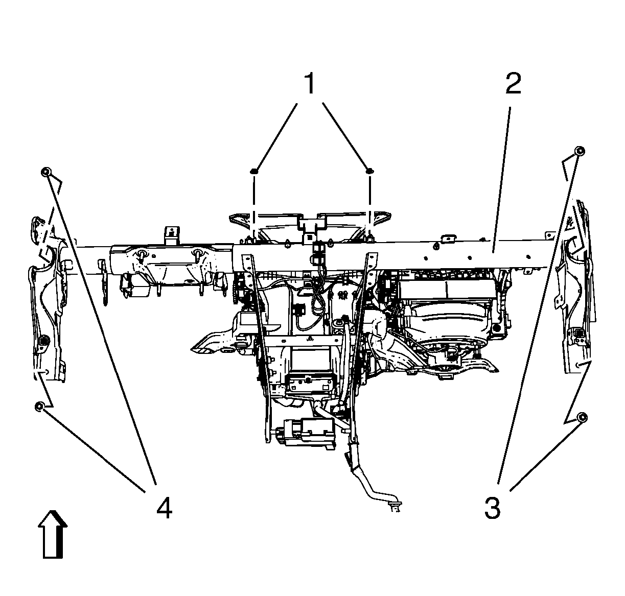
| • | Remove 4 instrument panel tie bar bolts (3 4). |
| • | Remove 2 instrument panel tie bar nuts (1). |
Installation Procedure
- Install 2 mode valve gear (1).
- Install mode control cam (1).
- Install instrument panel tie bar (2).
- Install instrument panel wiring harness (2) from instrument panel tie bar (1).
- Install instrument panel compartment assembly. Refer to Instrument Panel Compartment Replacement.
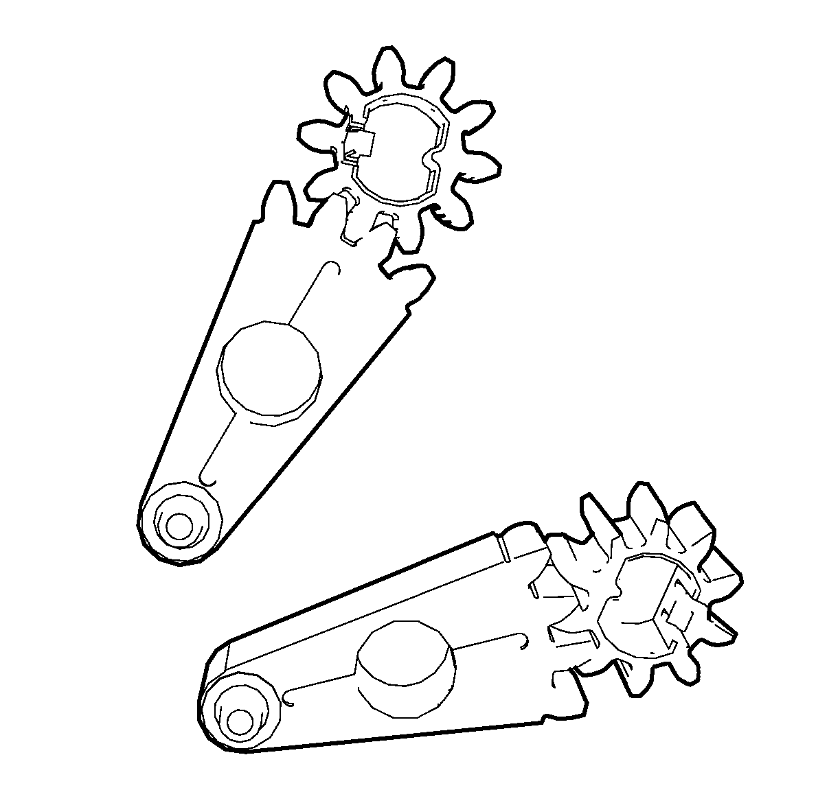
Note: The mode valve gear can only be fitted in one position. The mode valve gears have to be fitted to the according mode valve levers in figured position. The ventilation dampers have to be in middle position.

Note: The mode control cam can only be fitted in one position.
Caution: Refer to Fastener Caution in the Preface section.

| • | Install 4 instrument panel tie bar bolts (3, 4) and tighten to 22 N·m (16 lb ft). |
| • | Install 2 instrument panel tie bar nuts (1) and tighten to XXX N·m (XXX lb in). |

Connect electrical connectors.
