For 1990-2009 cars only
Removal Procedure
- Remove instrument panel compartment assembly. Refer to Instrument Panel Compartment Replacement.
- Remove instrument panel wiring harness (2) from instrument panel tie bar (1).
- Remove instrument panel tie bar (2).
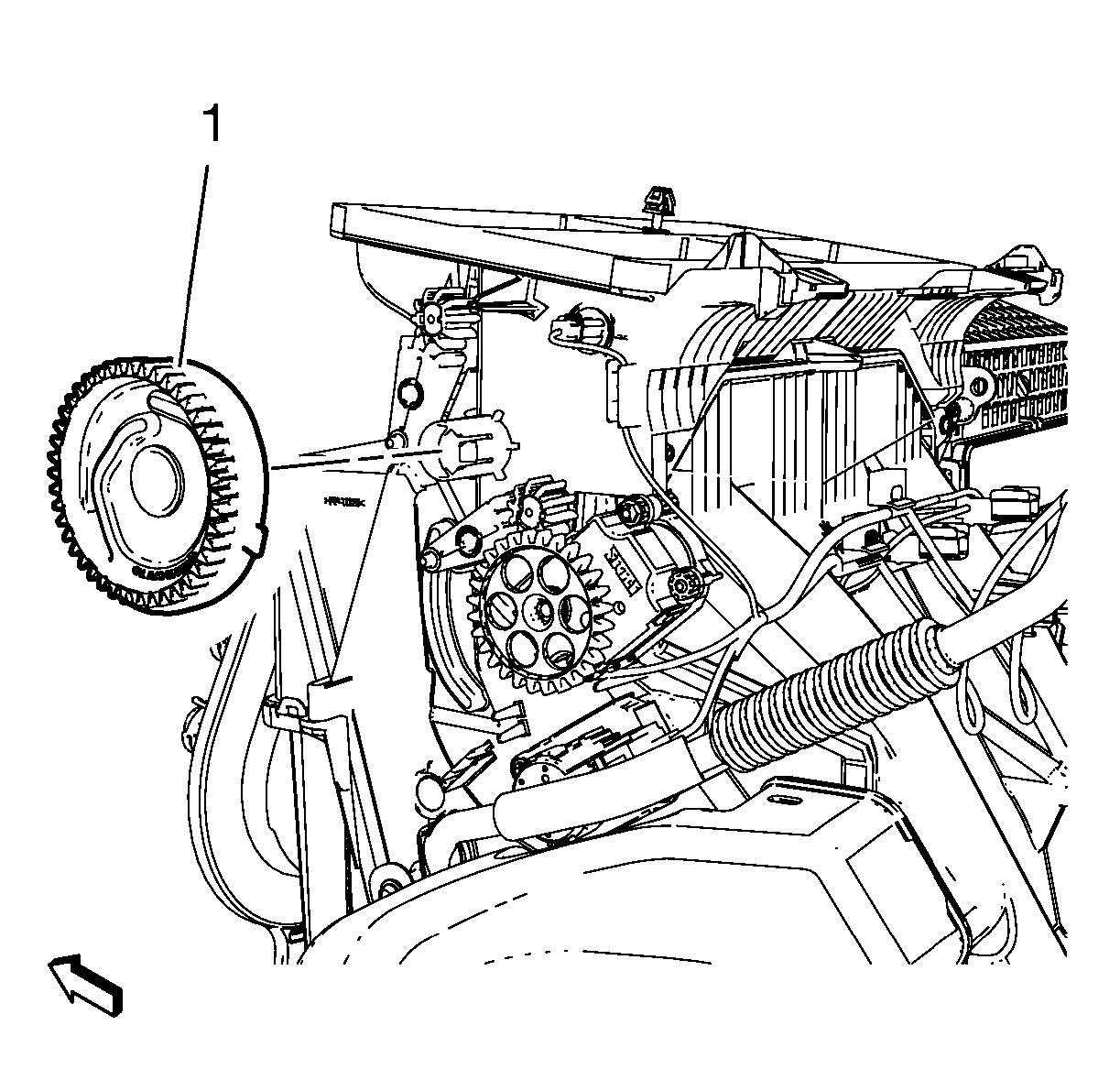
- Remove mode control cam (1).
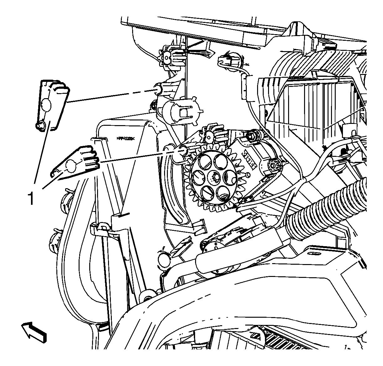
- Remove 2 mode valve lever (1).
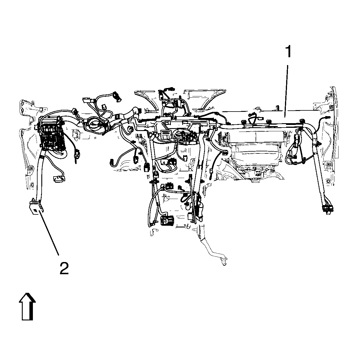
Disconnect electrical connectors.
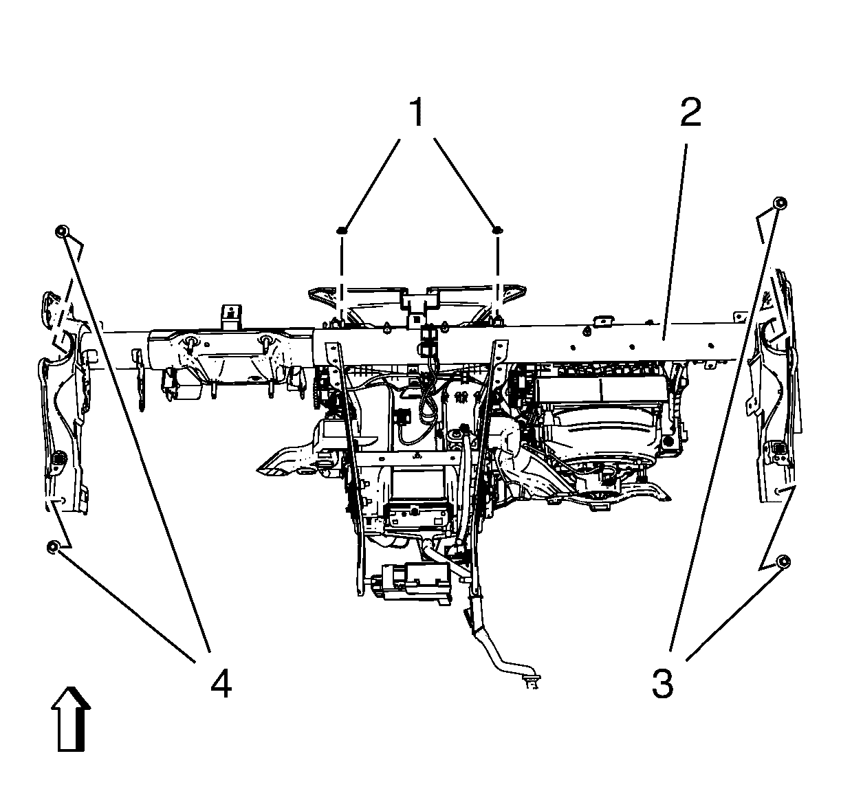
| • | Remove 4 instrument panel tie bar bolts (3, 4). |
| • | Remove 2 instrument panel tie bar nuts (1). |
Installation Procedure
- Install 2 mode valve lever (1).
- Install mode control cam (1).
- Install instrument panel tie bar (2).
- Install instrument panel wiring harness (2) from instrument panel tie bar (1).
- Install instrument panel compartment assembly. Refer to Instrument Panel Compartment Replacement.
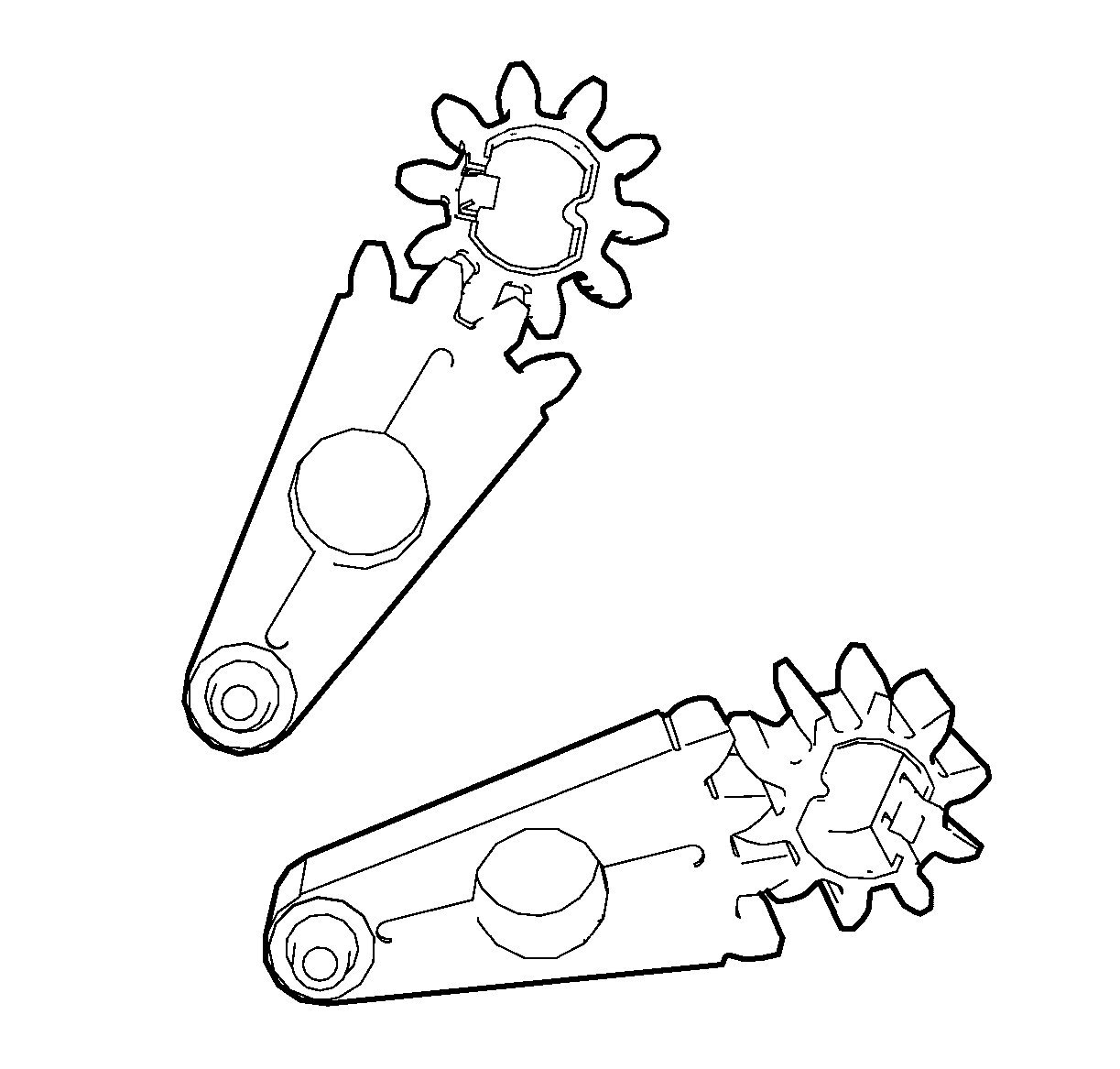
Note: The mode valve levers have to be fitted to the according mode valve gears in figured position. The ventilation dampers have to be in middle position.

Note: The mode control cam can only be fitted in one position.
Caution: Refer to Fastener Caution in the Preface section.

| • | Install 4 instrument panel tie bar bolts (3, 4) and tighten to XXX N·m (XXX lb in). |
| • | Install 2 instrument panel tie bar nuts (1) and tighten to XXX N·m (XXX lb in). |

Connect electrical connectors.
