For 1990-2009 cars only
Removal Procedure
- Remove instrument panel compartment assembly. Refer to Instrument Panel Compartment Replacement.
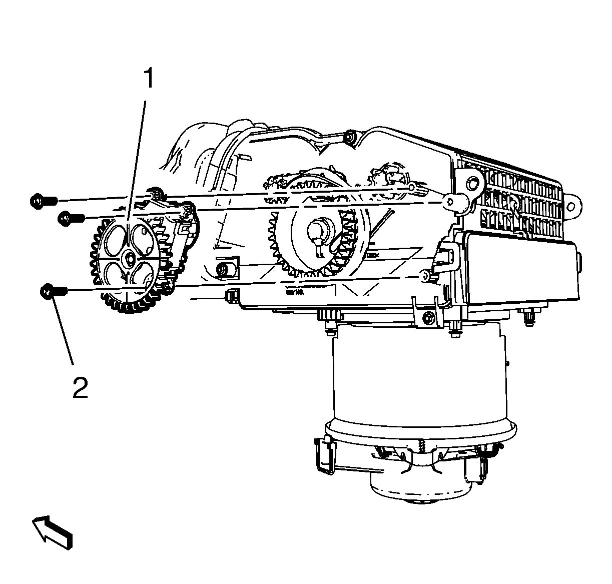
- Disconnect electrical connector and remove 3 mode control cam actuator screws (2) and remove mode control cam actuator (1).
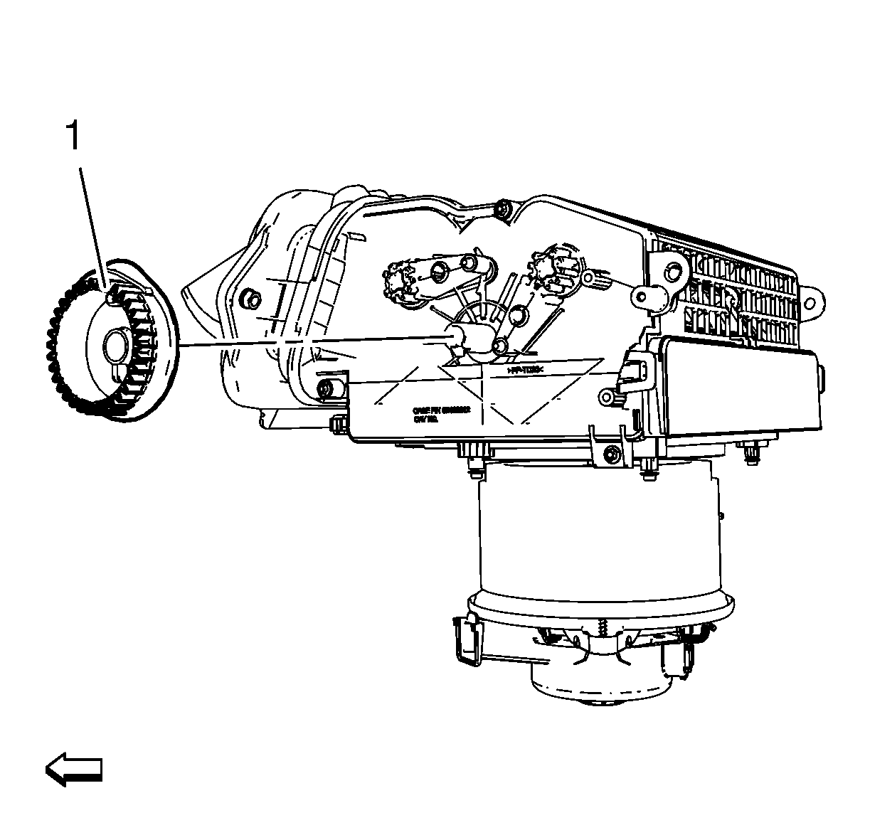
- Remove air inlet valve and inside air valve control cam (1).
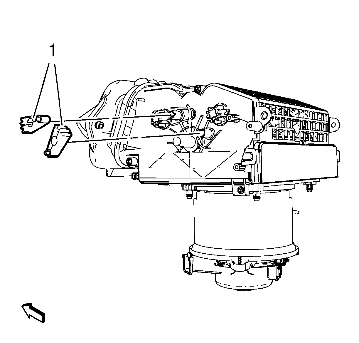
- Remove 2 vent valve levers (1).

Note: The graphic shows air inlet housing without attaching parts for better clarity.


Installation Procedure
- Install 2 vent valve levers (1).
- Install air inlet valve and inside air valve control cam (1).
- Install mode control cam actuator (1) and install 3 mode control cam actuator screws (2) and connect electrical connector.
- Install instrument panel compartment assembly. Refer to Instrument Panel Compartment Replacement.

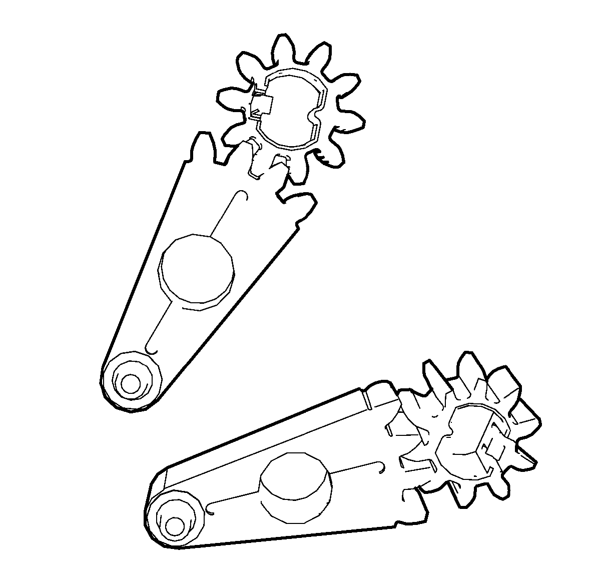
Note: The vent valve levers have to be fitted to the according vent valve gears in figured position. The air circulation dampers have to be in middle position.

Note: The air inlet valve and inside air valve control cam can only be fitted in one position.
Caution: Refer to Fastener Caution in the Preface section.

Tighten
2.5 N·m (23 lb in).
