| Figure 1: |
A11 Radio X1

Connector Part Information
|
Terminal Part Information
|
Pin | Wire | Circuit | Function |
|---|---|---|---|
2 | 0.35 Yellow | 7459 | Integrated Center Stack Serial Data Low (UAG/UFD) |
0.35 Yellow | 7459 | Integrated Center Stack Serial Data Low (UDK) | |
3 | 0.35 BARE | 7460 | Integrated Center Stack Serial Data Shield (UAG/UFD) |
0.35 BARE | 7460 | Integrated Center Stack Serial Data Shield (UDK) | |
6 | 0.5 Black-Yellow | 659 | Cellular Telephone Voice Low Reference |
10 | 0.35 Green | 5841 | Right Auxiliary Audio Signal (2) |
11 | 0.35 Blue | 2060 | Auxiliary Detection Signal |
13 | 0.35 Gray-Green | 3291 | Integrated Center Stack Wake Up Signal (UAG/UFD) |
0.35 Gray-Green | 3291 | Integrated Center Stack Wake Up Signal (UDK) | |
14 | 0.5 Green | 5060 | Low Speed GMLAN Serial Data |
15 | 0.5 Brown-Violet | 5748 | Radio Audio Mute Signal |
16 | 0.35 Violet | 7458 | Center Integrated Center Stack Serial Data High (UAG/UFD) |
0.35 Violet | 7458 | Center Integrated Center Stack Serial Data High (UDK) | |
20 | 0.5 Yellow | 658 | Cellular Telephone Voice Signal |
23 | 0.35 Violet | 5843 | Auxiliary Audio Common Signal |
24 | 0.35 Gray | 5839 | Left Auxiliary Audio Signal (2) |
27 | 0.35 Violet | 3290 | Integrated Center Stack Reset Signal (UAG/UFD) |
0.35 Violet | 3290 | Integrated Center Stack Reset Signal (UDK) | |
29 | 0.35 BARE | 2011 | Left Front Audio Drain Wire |
30 | 0.35 BARE | 2099 | Left Rear Audio Drain Wire |
31 | 0.35 Blue-Brown | 1546 | Front Low Level Audio (-) |
0.75 Yellow-Black | 117 | Right Front Speaker Signal (-) (1) (LHD UQG) | |
0.75 Yellow-Black | 117 | Right Front Speaker Signal (-) (1) (RHD UQG) | |
32 | 0.75 Brown-Blue | 118 | Left Front Speaker Signal (-) (1) (LHD UQG) |
0.75 Brown-Blue | 118 | Left Front Speaker Signal (-) (1) (RHD UQG) | |
0.35 Brown-Blue | 1947 | Left Front Low Level Audio (-) | |
33 | 0.75 Blue-Black | 115 | Right Rear Speaker Signal (-) (LHD UQG) |
0.75 Blue-Black | 115 | Right Rear Speaker Signal (-) (RHD UQG) | |
0.35 Blue-Black | 1946 | Right Rear Low Level Audio (-) | |
34 | 0.35 Brown-Violet | 1999 | Left Rear Low Level Audio (-) |
0.75 Green-Black | 116 | Left Rear Speaker Signal (-) (LHD UQG) | |
0.75 Green-Black | 116 | Left Rear Speaker Signal (-) (RHD UQG) | |
37 | 0.5 Violet-Blue | 6978 | Amplifier Control (UQG) |
38 | 1.5 Black | 50 | Ground |
39 | 0.35 Yellow | 512 | Right Front Low Level Audio Signal |
0.75 Yellow | 200 | Right Front Speaker (+) (1) (LHD UQG) | |
0.75 Yellow | 200 | Right Front Speaker (+) (1) (RHD UQG) | |
40 | 0.35 Blue | 511 | Left Front Low Level Audio Signal |
0.75 Blue | 201 | Left Front Speaker (+) (1) (LHD UQG) | |
0.75 Blue | 201 | Left Front Speaker (+) (1) (RHD UQG) | |
41 | 0.35 Brown-White | 546 | Right Rear Low Level Audio Signal |
0.75 White | 46 | Right Rear Speaker (+) (LHD UQG) | |
0.75 White | 46 | Right Rear Speaker (+) (RHD UQG) | |
42 | 0.75 Green | 199 | Left Rear Speaker (+) (LHD UQG) |
0.75 Green | 199 | Left Rear Speaker (+) (RHD UQG) | |
0.35 Green-Black | 599 | Left Rear Low Level Audio Signal | |
43 | 0.5 Green-Yellow | 7066 | Entertainment Remote Enable Signal (UQG) |
0.5 Green-Yellow | 7066 | Entertainment Remote Enable Signal (UDK) | |
44 | 1.5 Red-Green | 40 | Battery Positive Voltage |
A11 Radio X2

Connector Part Information
|
Terminal Part Information
|
Pin | Wire | Circuit | Function |
|---|---|---|---|
10 | 0.35 Brown-Green | 3364 | Navigation Display Reset Signal (UDK) |
14 | 0.35 Gray-Violet | 3363 | Navigation Display Dimming Control (UDK) |
20 | 0.5 Gray | 1903 | AAS Wheel Speed Sensor Signal Left Front |
0.5 Gray | 1903 | AAS Wheel Speed Sensor Signal Left Front (UDK) |
A22 Radio Control (UAG/UFD)
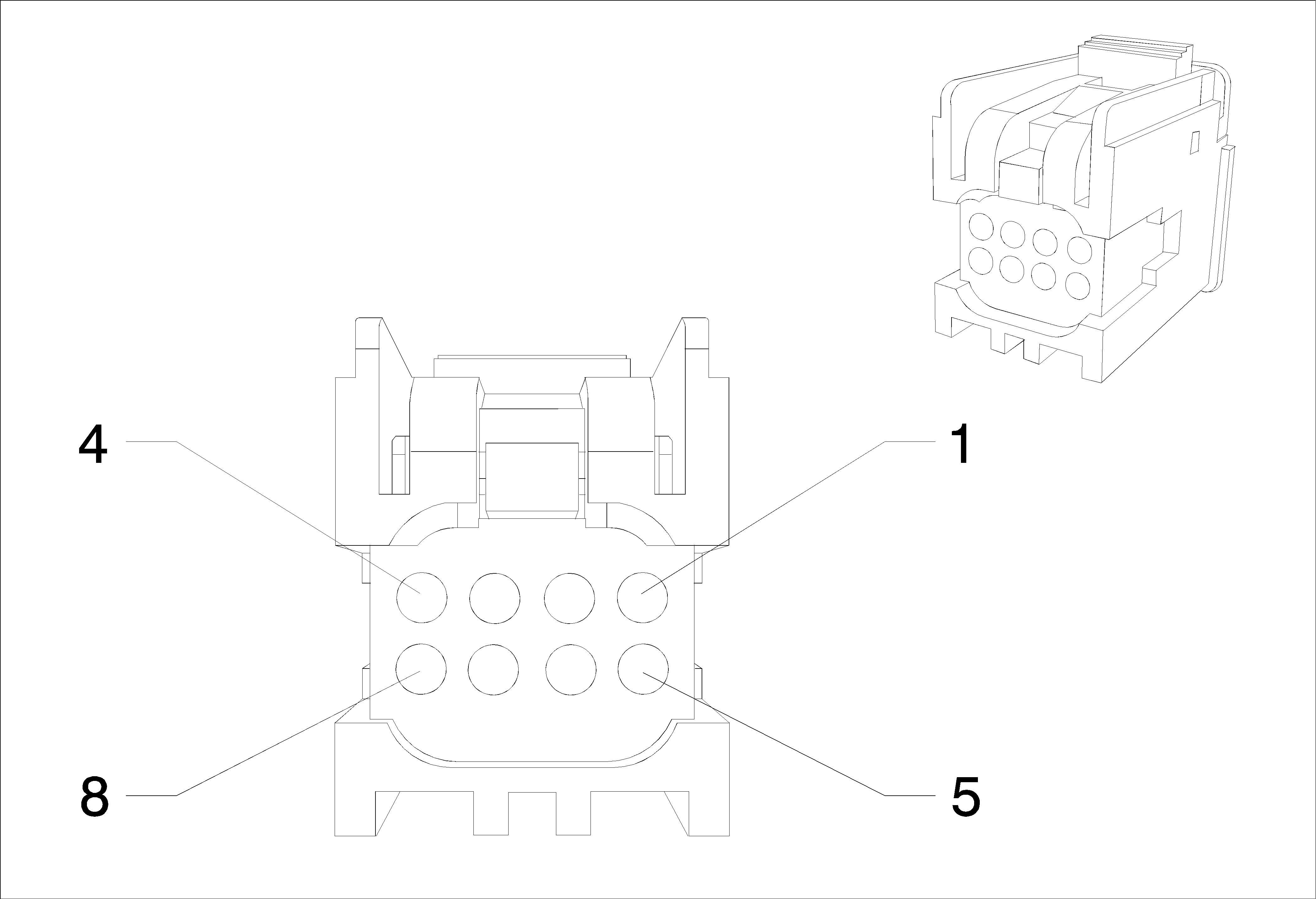
Connector Part Information
|
Terminal Part Information
|
Pin | Wire | Circuit | Function |
|---|---|---|---|
1 | 0.5 Red-Green | 40 | Battery Positive Voltage |
0.5 Red-Green | 40 | Battery Positive Voltage | |
2 | 0.5 Black | 50 | Ground |
0.5 Black | 50 | Ground | |
4 | 0.5 Green-Blue | 7532 | Linear Interconnect Network Bus 10 |
A22 Radio Control (UDK)

Connector Part Information
|
Terminal Part Information
|
Pin | Wire | Circuit | Function |
|---|---|---|---|
1 | 0.5 Red-Green | 40 | Battery Positive Voltage |
0.5 Red-Green | 40 | Battery Positive Voltage | |
2 | 0.5 Black | 50 | Ground |
0.5 Black | 50 | Ground | |
4 | 0.35 Gray-Green | 3291 | Integrated Center Stack Wake Up Signal |
5 | 0.35 Violet | 3290 | Integrated Center Stack Reset Signal |
6 | 0.35 BARE | 7460 | Integrated Center Stack Serial Data Shield |
7 | 0.35 Violet | 7458 | Center Integrated Center Stack Serial Data High |
8 | 0.35 Yellow | 7459 | Integrated Center Stack Serial Data Low |
A23C Door Latch Assembly - Liftgate

Connector Part Information
|
Terminal Part Information
|
Pin | Wire | Circuit | Function |
|---|---|---|---|
1 | 0.5 Blue-Yellow | 6795 | Lift Glass/Trunk Motor Release Control 2 |
2 | 0.5 Black | 50 | Ground |
4 | 0.5 Violet-Gray | 1303 | Lift Gate Ajar Switch Signal (1) |
A23D Door Latch Assembly - Driver

Connector Part Information
|
Terminal Part Information
|
Pin | Wire | Circuit | Function |
|---|---|---|---|
1 | 0.75 Brown | 5910 | Door Double Lock Actuator Lock Control (LHD AF8-SAE) |
0.5 Gray | 745 | Left Front Door Ajar Switch Signal (RHD AEC) | |
0.5 Gray | 745 | Left Front Door Ajar Switch Signal (RHD -AED/-AXG) | |
0.5 Gray | 745 | Left Front Door Ajar Switch Signal (RHD AXG) | |
2 | 0.75 Brown-Yellow | 294 | Door Lock Actuator Unlock Control (LHD -AF8) |
0.75 Brown-Yellow | 294 | Door Lock Actuator Unlock Control (LHD AF8-SAE) | |
0.5 White-Yellow | 3574 | Driver Door Open Switch Signal (RHD ATH) | |
3 | 0.75 Gray | 295 | Door Lock Actuator Lock Control (LHD -AF8) |
0.75 Gray | 295 | Door Lock Actuator Lock Control (LHD AF8-SAE) | |
0.75 Black | 50 | Ground (RHD LHD ATH) | |
0.75 Black | 50 | Ground (RHD RHD ATH) | |
0.75 Black | 50 | Ground (RHD) | |
0.75 Black | 50 | Ground | |
0.75 Black | 50 | Ground (RHD) | |
4 | 0.5 Gray-Black | 9990 | - (LHD) |
5 | 0.75 Violet-Blue | 6666 | Driver Door Unlatch Motor Unlatch Control (RHD ATH) |
0.75 Gray | 3578 | Driver Door Unlatch Motor Unlatch Return (LHD ATH) | |
6 | 0.75 Brown | 5910 | Door Double Lock Actuator Lock Control (RHD AF8-SAE) |
0.5 Gray | 745 | Left Front Door Ajar Switch Signal (LHD AEC) | |
0.5 Gray | 745 | Left Front Door Ajar Switch Signal (LHD -AED/-AXG) | |
0.5 Gray | 745 | Left Front Door Ajar Switch Signal (LHD AXG) | |
7 | 0.75 Brown-Yellow | 294 | Door Lock Actuator Unlock Control (RHD -AF8) |
0.75 Brown-Yellow | 294 | Door Lock Actuator Unlock Control (RHD AF8-SAE) | |
0.5 White-Yellow | 3574 | Driver Door Open Switch Signal (LHD ATH) | |
8 | 0.75 Gray | 295 | Door Lock Actuator Lock Control (RHD -AF8) |
0.75 Gray | 295 | Door Lock Actuator Lock Control (RHD AF8-SAE) | |
0.75 Black | 50 | Ground | |
0.75 Black | 50 | Ground (LHD) | |
0.75 Black | 50 | Ground (LHD LHD ATH) | |
0.75 Black | 50 | Ground (RHD LHD ATH) | |
0.75 Black | 50 | Ground (LHD) | |
9 | 0.5 Gray-Black | 9990 | - (RHD) |
10 | 0.75 Violet-Blue | 6666 | Driver Door Unlatch Motor Unlatch Control (LHD ATH) |
0.75 Gray | 3578 | Driver Door Unlatch Motor Unlatch Return (RHD ATH) |
A23LR Door Latch Assembly - Left Rear

Connector Part Information
|
Terminal Part Information
|
Pin | Wire | Circuit | Function |
|---|---|---|---|
1 | 0.75 Brown | 5910 | Door Double Lock Actuator Lock Control ( AF8-SAE) |
2 | 0.75 Brown-Yellow | 294 | Door Lock Actuator Unlock Control ( -AF8) |
0.75 Brown-Yellow | 294 | Door Lock Actuator Unlock Control ( AF8-SAE) | |
3 | 0.75 Gray | 295 | Door Lock Actuator Lock Control ( -AF8) |
0.75 Gray | 295 | Door Lock Actuator Lock Control ( AF8-SAE) | |
4 | 0.75 Brown-Yellow | 294 | Door Lock Actuator Unlock Control (SAE -AF8) |
5 | 0.75 Blue-Yellow | 3580 | Left Rear Door Unlatch Motor Unlatch Return (ATH) |
6 | 0.5 Gray | 747 | Left Rear Door Ajar Switch Signal (AEQ) |
0.5 Gray | 747 | Left Rear Door Ajar Switch Signal (-AEQ) | |
7 | 0.75 White-Blue | 3266 | Child Security Lock Motor Unlock Control ( -AF8) |
8 | 0.75 Black | 50 | Ground |
9 | 0.5 Brown-White | 3269 | Child Security Lock Motor Status Signal Left Rear |
10 | 0.75 Blue-White | 6667 | Left Rear Door Unlatch Motor Unlatch Control (ATH) |
A23P Door Latch Assembly - Passenger

Connector Part Information
|
Terminal Part Information
|
Pin | Wire | Circuit | Function |
|---|---|---|---|
1 | 0.75 Brown | 5910 | Door Double Lock Actuator Lock Control (RHD AF8-SAE) |
0.5 Gray | 746 | Right Front Door Ajar Switch Signal (LHD AED) | |
0.5 Gray | 746 | Right Front Door Ajar Switch Signal (LHD -AED) | |
2 | 0.75 Brown-Yellow | 294 | Door Lock Actuator Unlock Control (RHD -AF8) |
0.75 Brown-Yellow | 294 | Door Lock Actuator Unlock Control (RHD AF8-SAE) | |
0.5 Gray-Green | 3575 | Co_Driver Door Open Switch Signal (LHD ATH) | |
3 | 0.75 Gray | 295 | Door Lock Actuator Lock Control (RHD -AF8) |
0.75 Gray | 295 | Door Lock Actuator Lock Control (RHD AF8-SAE) | |
0.75 Black | 50 | Ground (LHD) | |
0.75 Black | 50 | Ground (LHD LHD ATH) | |
0.75 Black | 50 | Ground (RHD LHD ATH) | |
0.75 Black | 50 | Ground (LHD) | |
5 | 0.75 Gray-Black | 3579 | Co Driver Door Unlatch Motor Unlatch Return (RHD ATH) |
0.75 Yellow-Green | 3583 | Co Driver Door Unlatch Motor Unlatch Control (LHD ATH) | |
6 | 0.75 Brown | 5910 | Door Double Lock Actuator Lock Control (LHD AF8-SAE) |
0.5 Gray | 746 | Right Front Door Ajar Switch Signal (RHD AED) | |
0.5 Gray | 746 | Right Front Door Ajar Switch Signal (RHD -AED) | |
7 | 0.75 Brown-Yellow | 294 | Door Lock Actuator Unlock Control (LHD -AF8) |
0.75 Brown-Yellow | 294 | Door Lock Actuator Unlock Control (LHD AF8-SAE) | |
0.5 Gray-Green | 3575 | Co_Driver Door Open Switch Signal (RHD ATH) | |
8 | 0.75 Gray | 295 | Door Lock Actuator Lock Control (LHD -AF8) |
0.75 Gray | 295 | Door Lock Actuator Lock Control (LHD AF8-SAE) | |
0.75 Black | 50 | Ground (RHD) | |
0.75 Black | 50 | Ground (RHD LHD ATH) | |
0.75 Black | 50 | Ground (RHD RHD ATH) | |
0.75 Black | 50 | Ground (RHD) | |
10 | 0.75 Gray-Black | 3579 | Co Driver Door Unlatch Motor Unlatch Return (LHD ATH) |
0.75 Yellow-Green | 3583 | Co Driver Door Unlatch Motor Unlatch Control (RHD ATH) |
A23RR Door Latch Assembly - Right Rear

Connector Part Information
|
Terminal Part Information
|
Pin | Wire | Circuit | Function |
|---|---|---|---|
1 | 0.5 Gray | 748 | Right Rear Door Ajar Switch Signal (AEQ) |
0.5 Gray | 748 | Right Rear Door Ajar Switch Signal (-AEQ) | |
2 | 0.75 White-Blue | 3266 | Child Security Lock Motor Unlock Control ( -AF8) |
3 | 0.75 Black | 50 | Ground |
4 | 0.5 Gray-Black | 3268 | Child Security Lock Motor Status Signal Right Rear |
5 | 0.75 Green-Black | 6669 | Right Rear Door Unlatch Motor Unlatch Control (ATH) |
6 | 0.75 Brown | 5910 | Door Double Lock Actuator Lock Control ( AF8-SAE) |
7 | 0.75 Brown-Yellow | 294 | Door Lock Actuator Unlock Control ( -AF8) |
0.75 Brown-Yellow | 294 | Door Lock Actuator Unlock Control ( AF8-SAE) | |
8 | 0.75 Gray | 295 | Door Lock Actuator Lock Control ( -AF8) |
0.75 Gray | 295 | Door Lock Actuator Lock Control ( AF8-SAE) | |
9 | 0.75 Brown-Yellow | 294 | Door Lock Actuator Unlock Control (SAE -AF8) |
10 | 0.75 Green-White | 3581 | Right Rear Door Unlatch Motor Unlatch Return (ATH) |
A3L Sunshade - Left
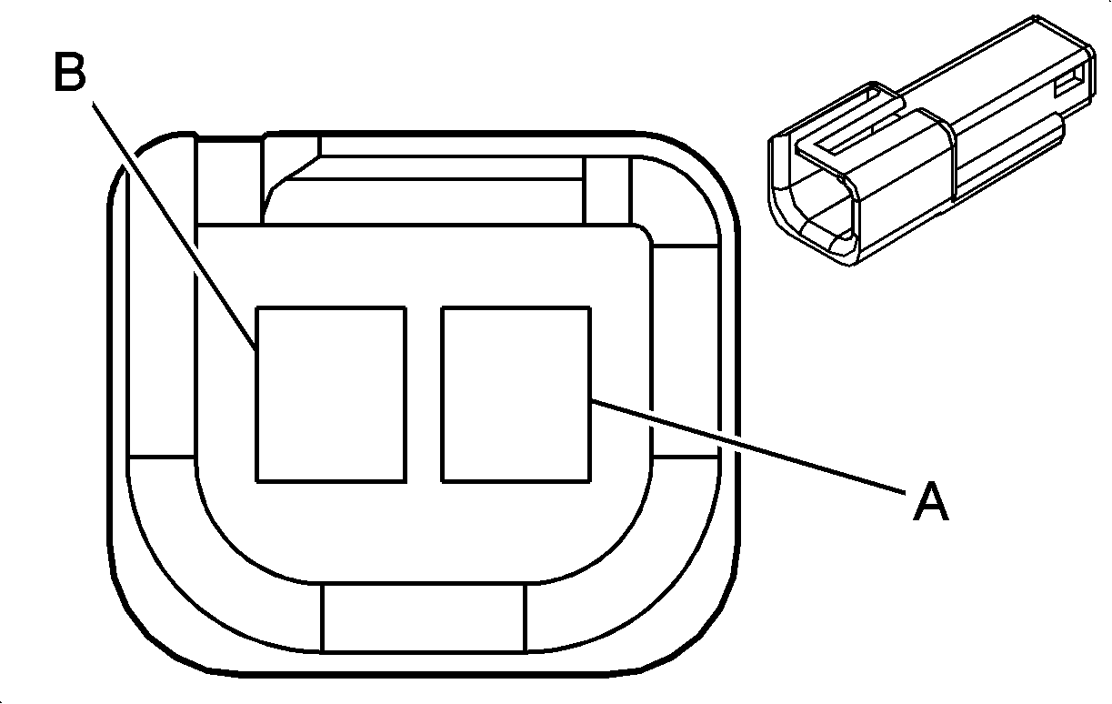
Connector Part Information
|
Terminal Part Information
|
Pin | Wire | Circuit | Function |
|---|---|---|---|
A | 1 White-Brown | 6815 | Inadvertent Power Control |
B | 0.5 Black | 50 | Ground |
A3R Sunshade - Right

Connector Part Information
|
Terminal Part Information
|
Pin | Wire | Circuit | Function |
|---|---|---|---|
A | 1 White-Brown | 6815 | Inadvertent Power Control |
B | 0.5 Black | 50 | Ground |
A9A Outside Rearview Mirror - Driver
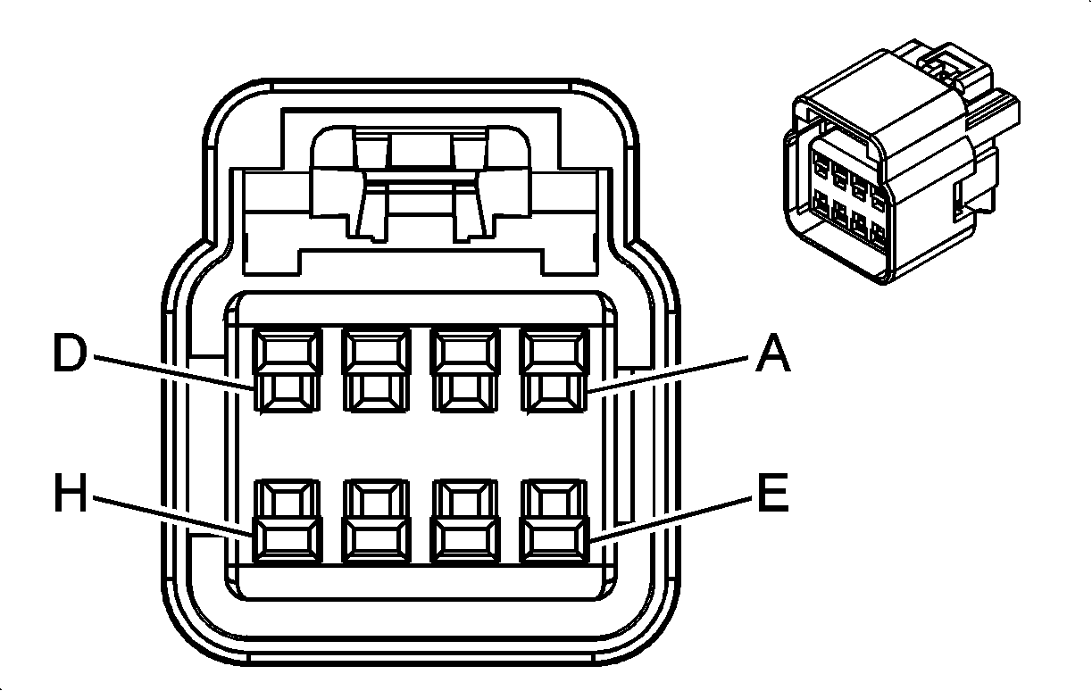
Connector Part Information
|
Terminal Part Information
|
Pin | Wire | Circuit | Function |
|---|---|---|---|
A | 0.5 Yellow-Brown | 3391 | Driver Mirror Motor Common Control |
B | 0.5 Violet-Blue | 3390 | Driver Mirror Motor Up (+) Down (-) Control |
C | 0.5 Brown-Black | 3389 | Driver Mirror Motor Right (+) Left (-) Control |
D | 0.5 Violet-Yellow | 3409 | Mirror Motor Fold Out Control |
E | 0.5 White-Brown | 3410 | Mirror Motor Fold In Control |
F | 0.5 Brown-Yellow | 2267 | Mirror Heating Element Control |
G | 0.5 Black | 50 | Ground |
A9B Outside Rearview Mirror - Passenger

Connector Part Information
|
Terminal Part Information
|
Pin | Wire | Circuit | Function |
|---|---|---|---|
A | 0.5 White | 3398 | Co-Driver Mirror Motor Common Control |
B | 0.5 Yellow-Violet | 3397 | Co-Driver Mirror Motor Up (+) Down (-) Control |
C | 0.5 Green-Black | 3396 | Co-Driver Mirror Motor Right (+) Left (-) Control |
D | 0.5 Violet-Yellow | 3409 | Mirror Motor Fold Out Control |
E | 0.5 White-Brown | 3410 | Mirror Motor Fold In Control |
F | 0.5 Brown-Yellow | 2267 | Mirror Heating Element Control |
G | 0.5 Black | 50 | Ground |
B107 Accelerator Pedal Position Sensor

Connector Part Information
|
Terminal Part Information
|
Pin | Wire | Circuit | Function |
|---|---|---|---|
1 | 0.5 Brown-Red | 1274 | Accelerator Pedal Position 5 Volt Reference (2) (LDE/LXV/2H0) |
0.5 Brown-Red | 1274 | Accelerator Pedal Position 5 Volt Reference (2) (LLW) | |
0.5 Brown-Red | 1274 | Accelerator Pedal Position 5 Volt Reference (2) (LXT -SAE) | |
2 | 0.5 White-Red | 1164 | Accelerator Pedal Position 5 Volt Reference (1) (LDE/LXV/2H0) |
0.5 White-Red | 1164 | Accelerator Pedal Position 5 Volt Reference (1) (LLW) | |
0.5 White-Red | 1164 | Accelerator Pedal Position 5 Volt Reference (1) (LXT -SAE) | |
3 | 0.5 Yellow-White | 1161 | Accelerator Pedal Position Signal (1) (LDE/LXV/2H0) |
0.5 Yellow-White | 1161 | Accelerator Pedal Position Signal (1) (LLW) | |
0.5 Yellow-White | 1161 | Accelerator Pedal Position Signal (1) (LXT -SAE) | |
4 | 0.5 Black-Blue | 1271 | Accelerator Pedal Position Low Reference (1) (LDE/LXV/2H0) |
0.5 Black-Blue | 1271 | Accelerator Pedal Position Low Reference (1) (LLW) | |
0.5 Black-Blue | 1271 | Accelerator Pedal Position Low Reference (1) (LXT -SAE) | |
5 | 0.5 Black-Violet | 1272 | Accelerator Pedal Position Low Reference (2) (LDE/LXV/2H0) |
0.5 Black-Violet | 1272 | Accelerator Pedal Position Low Reference (2) (LLW) | |
0.5 Black-Violet | 1272 | Accelerator Pedal Position Low Reference (2) (LXT -SAE) | |
6 | 0.5 Green-White | 1162 | Accelerator Pedal Position Signal (2) (LDE/LXV/2H0) |
0.5 Green-White | 1162 | Accelerator Pedal Position Signal (2) (LLW) | |
0.5 Green-White | 1162 | Accelerator Pedal Position Signal (2) (LXT -SAE) |
B108 Air Quality Sensor

Connector Part Information
|
Terminal Part Information
|
Pin | Wire | Circuit | Function |
|---|---|---|---|
1 | 0.5 Violet-Green | 39 | Ignition Voltage |
0.5 Violet-Green | 1339 | Run/Crank Ignition 1 Voltage | |
2 | 0.5 Black | 50 | Ground |
3 | 0.5 Violet-White | 5203 | Air Quality Sensor Signal |
B10B Light/Sunload Sensor - Ambient

Connector Part Information
|
Terminal Part Information
|
Pin | Wire | Circuit | Function |
|---|---|---|---|
2 | 0.35 Gray | 590 | Solar Sensor Driver Signal (CJ2) |
3 | 0.35 Blue-White | 734 | Inside Air Temperature Sensor Signal (CJ2) |
4 | 0.35 Blue | 1120 | - (CJ2) |
6 | 0.85 Black | 50 | Ground |
0.35 Black | 50 | Ground (CJ2) | |
0.35 Black-Blue | 50 | Ground (C68) | |
0.35 Black-Blue | 7566 | Humidity/Windscreen Temp Sensor Low Reference (CJ2) |
B111 Boost Pressure Sensor (LLW)

Connector Part Information
|
Terminal Part Information
|
Pin | Wire | Circuit | Function |
|---|---|---|---|
1 | 0.5 Green | 1533 | Turbo Boost Pressure Sensor Signal |
2 | 0.5 Brown-Red | 5639 | Turbo Boost Pressure Sensor 5 Volt Reference |
3 | 0.5 Gray | 5641 | Turbo Boost Pressure Sensor Temperature Signal |
4 | 0.5 White | 5637 | Outside Rear View Mirror Select Signal |
B117 Rain Sensor

Connector Part Information
|
Terminal Part Information
|
Pin | Wire | Circuit | Function |
|---|---|---|---|
1 | 0.5 Red-White | 40 | Battery Positive Voltage |
2 | 0.5 Black | 50 | Ground |
3 | 0.5 Green-Brown | 6132 | Linear Interconnect Network Bus 1 |
B14E Output Speed Sensor (LDE/LXV/2H0)
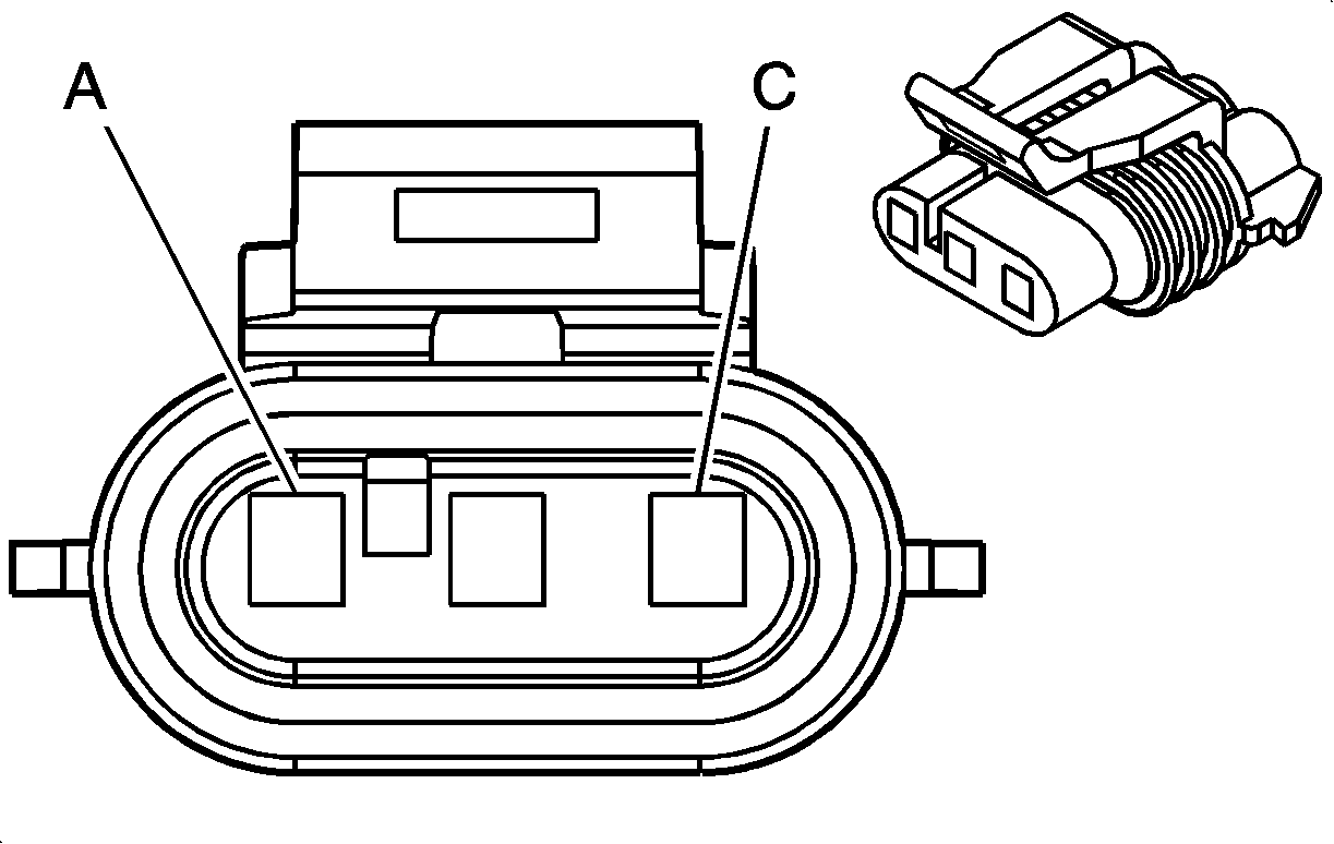
Connector Part Information
|
Terminal Part Information
|
Pin | Wire | Circuit | Function |
|---|---|---|---|
A | 0.5 Black-Violet | 50 | Ground |
B | 0.5 Green-Gray | 817 | Vehicle Speed Signal |
C | 0.5 Brown-Violet | 5290 | Powertrain Main Relay Fused Supply (1) |
B14E Output Speed Sensor (LLW)

Connector Part Information
|
Terminal Part Information
|
Pin | Wire | Circuit | Function |
|---|---|---|---|
A | 0.5 Black | 50 | Ground |
0.5 Black | 50 | Ground | |
B | 0.5 Green-Gray | 817 | Vehicle Speed Signal |
C | 1 Violet-Black | 3 | Ignition Voltage |
B14E Output Speed Sensor (LXT)

Connector Part Information
|
Terminal Part Information
|
Pin | Wire | Circuit | Function |
|---|---|---|---|
A | 0.5 Black | 50 | Ground |
0.5 Black-White | 50 | Ground | |
B | 0.5 Green-Gray | 817 | Vehicle Speed Signal |
C | 0.75 Violet-Black | 3 | Ignition Voltage |
B16 Backup Lamp Switch (LDE/LXV/2H0)

Connector Part Information
|
Terminal Part Information
|
Pin | Wire | Circuit | Function |
|---|---|---|---|
A | 0.5 Gray-Black | 6316 | Engine Reverse Gear Switch Signal |
B | 0.5 Black | 50 | Ground |
0.5 Black | 50 | Ground |
B16 Backup Lamp Switch (LLW)

Connector Part Information
|
Terminal Part Information
|
Pin | Wire | Circuit | Function |
|---|---|---|---|
A | 0.5 Gray-Black | 6316 | Engine Reverse Gear Switch Signal |
B | 0.5 Black | 50 | Ground |
0.5 Black | 50 | Ground |
B16 Backup Lamp Switch (LXT)

Connector Part Information
|
Terminal Part Information
|
Pin | Wire | Circuit | Function |
|---|---|---|---|
A | 0.5 Blue-Violet | 6316 | Engine Reverse Gear Switch Signal |
B | 0.5 Brown | 50 | Ground |
0.5 Brown | 50 | Ground |
B160 Windshield Temperature and Inside Moisture Sensor

Connector Part Information
|
Terminal Part Information
|
Pin | Wire | Circuit | Function |
|---|---|---|---|
1 | 0.35 Yellow-Red | 597 | 5 Volt Reference (CJ2) |
2 | 0.35 Gray-Blue | 7564 | Humidity Sensor Signal (CJ2) |
3 | 0.35 Black-Blue | 7566 | Humidity/Windscreen Temp Sensor Low Reference (CJ2) |
0.35 Dark Green | 50 | Ground | |
4 | 0.35 Gray-Green | 7565 | Windscreen Temp Sensor Signal (CJ2) |
5 | 0.35 Yellow-Blue | 3197 | Humidity Temperature Sensor Signal (CJ2) |
B18 Battery Current Sensor
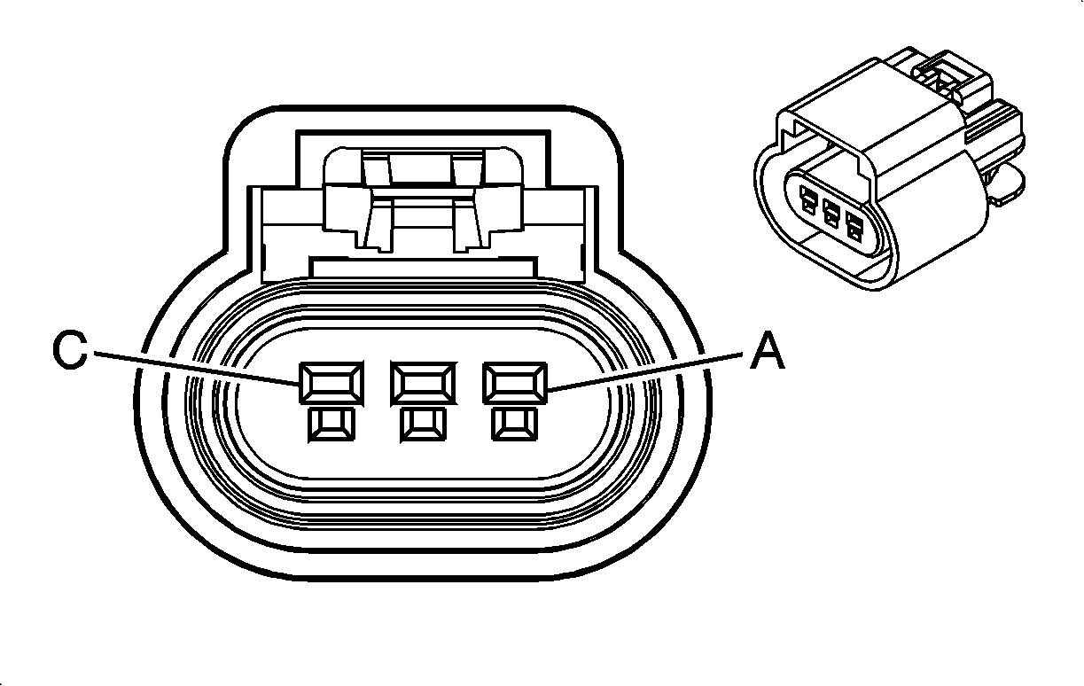
Connector Part Information
|
Terminal Part Information
|
Pin | Wire | Circuit | Function |
|---|---|---|---|
B20 Brake Fluid Level Switch

Connector Part Information
|
Terminal Part Information
|
Pin | Wire | Circuit | Function |
|---|---|---|---|
1 | 0.5 Green-Gray | 333 | Brake Fluid Level Sensor Signal (JL9) |
0.5 Green-Gray | 333 | Brake Fluid Level Sensor Signal (-JL9) | |
2 | 0.5 Black | 50 | Ground |
1.25 Black | 50 | Ground |
B22 Brake Pedal Position Sensor
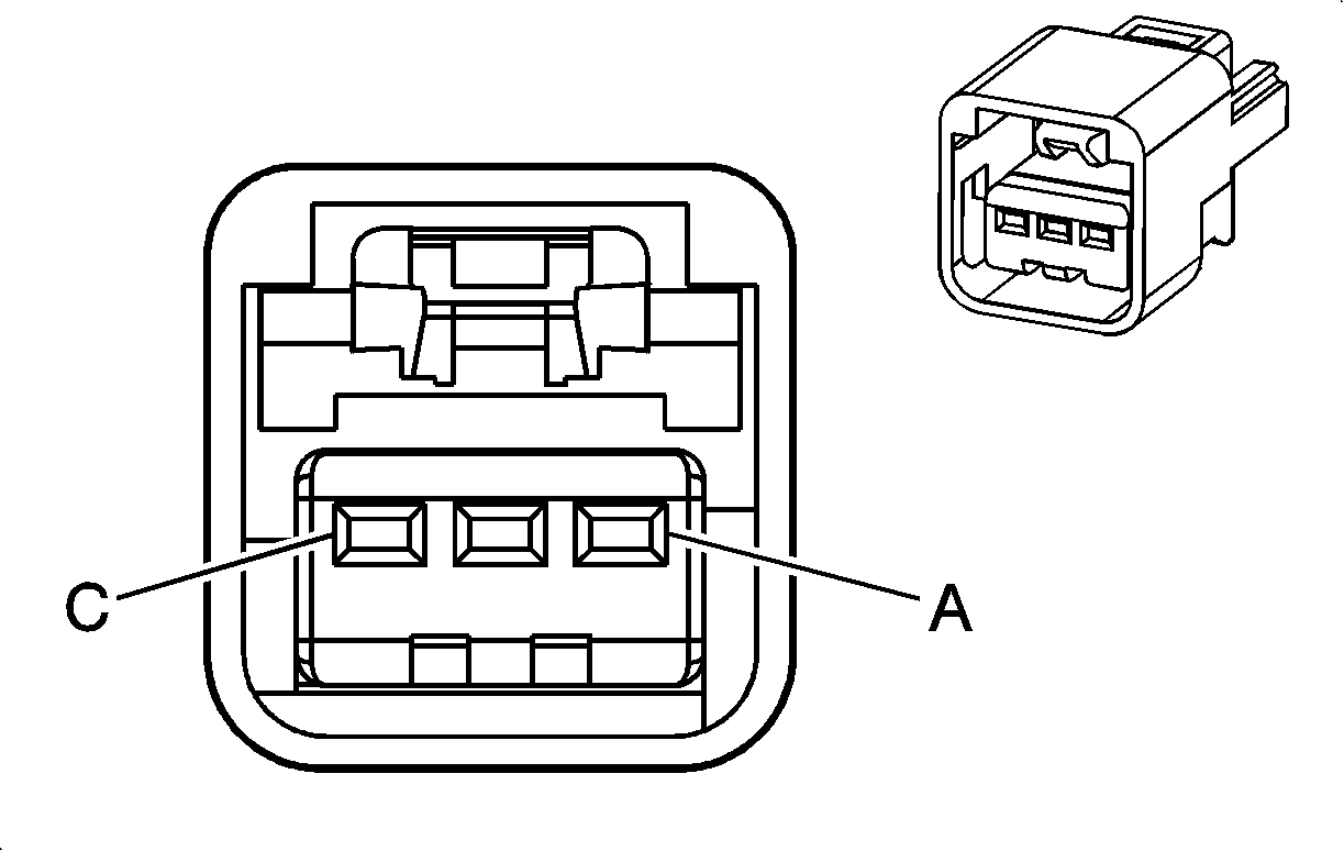
Connector Part Information
|
Terminal Part Information
|
Pin | Wire | Circuit | Function |
|---|---|---|---|
A | 0.5 Black-Brown | 5360 | Brake Apply Sensor Low Reference |
B | 0.5 Blue-Yellow | 5361 | Brake Apply Sensor Signal |
C | 0.5 White | 5359 | Brake Apply Sensor Supply Voltage |
B23 Camshaft Position Sensor (LLW)
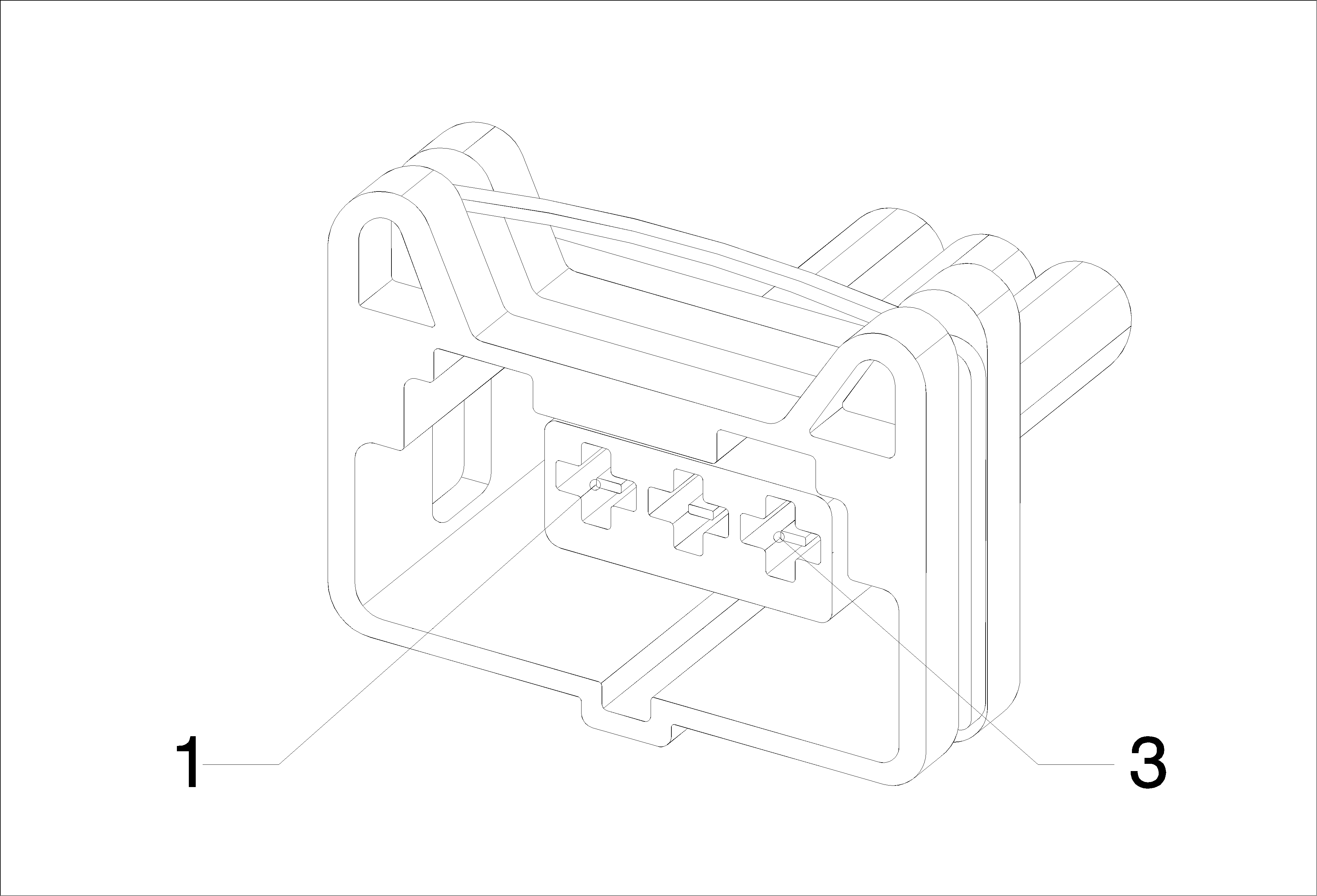
Connector Part Information
|
Terminal Part Information
|
Pin | Wire | Circuit | Function |
|---|---|---|---|
1 | 0.5 Yellow-Violet | 633 | Camshaft Position Sensor Signal |
2 | 0.5 Black-Yellow | 632 | Camshaft Position Sensor Low Reference |
3 | 0.75 Violet-Blue | 5291 | Powertrain Main Relay Fused Supply (2) |
0.5 Violet-Blue | 5291 | Powertrain Main Relay Fused Supply (2) |
B23 Camshaft Position Sensor (LXT)

Connector Part Information
|
Terminal Part Information
|
Pin | Wire | Circuit | Function |
|---|---|---|---|
1 | 0.5 Violet-Blue | 5291 | Powertrain Main Relay Fused Supply (2) |
0.5 Violet-Blue | 5291 | Powertrain Main Relay Fused Supply (2) | |
2 | 0.5 Black-White | 50 | Ground |
0.5 Black-White | 51 | Signal Ground | |
3 | 0.5 Yellow-Violet | 633 | Camshaft Position Sensor Signal |
B24 Cellular Phone Microphone

Connector Part Information
|
Terminal Part Information
|
Pin | Wire | Circuit | Function |
|---|---|---|---|
A | 0.5 BARE | 5193 | Noise Reduction Microphone Screen |
B | 0.5 Yellow | 5191 | Noise Reduction Microphone Active Signal |
B25B Clutch Pedal Position Sensor

Connector Part Information
|
Terminal Part Information
|
Pin | Wire | Circuit | Function |
|---|---|---|---|
A | 0.5 Black-Gray | 6110 | Clutch Apply Sensor Low Reference |
B | 0.5 Yellow | 6111 | Clutch Apply Sensor Signal |
C | 0.5 Gray-Red | 6109 | Clutch Apply Sensor Voltage Reference |
B26 Crankshaft Position Sensor (LDE/LXV/2H0)
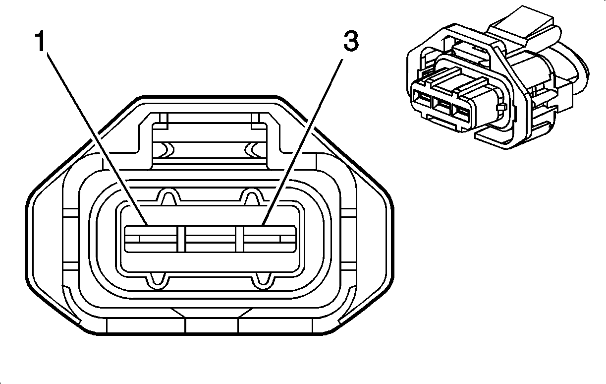
Connector Part Information
|
Terminal Part Information
|
Pin | Wire | Circuit | Function |
|---|---|---|---|
1 | 0.5 White-Black | 1799 | Crankshaft Position Sensor High Resolution Signal |
2 | 0.5 Black-Violet | 574 | Crankshaft Sensor Low Reference (1) |
3 | 0.5 Green | 573 | Crankshaft Sensor Signal (1) |
B26 Crankshaft Position Sensor (LLW)

Connector Part Information
|
Terminal Part Information
|
Pin | Wire | Circuit | Function |
|---|---|---|---|
1 | 0.5 White-Black | 1799 | Crankshaft Position Sensor High Resolution Signal |
2 | 0.5 Green | 573 | Crankshaft Sensor Signal (1) |
3 | 0.5 Black-Violet | 574 | Crankshaft Sensor Low Reference (1) |
B26 Crankshaft Position Sensor (LXT)

Connector Part Information
|
Terminal Part Information
|
Pin | Wire | Circuit | Function |
|---|---|---|---|
1 | 0.5 White-Black | 1799 | Crankshaft Position Sensor High Resolution Signal |
2 | 0.5 Green | 573 | Crankshaft Sensor Signal (1) |
0.5 Black | 50 | Ground | |
3 | 0.5 Black-Violet | 50 | Ground |
B27D Door Handle Switch - Driver

Connector Part Information
|
Terminal Part Information
|
Pin | Wire | Circuit | Function |
|---|---|---|---|
1 | 0.5 Black | 50 | Ground (ATH) |
0.75 Black | 50 | Ground (LHD) | |
0.75 Black | 50 | Ground (RHD) | |
2 | 0.5 Green-White | 3570 | Driver Door Handle Switch Signal |
B27LR Door Handle Switch - Left Rear

Connector Part Information
|
Terminal Part Information
|
Pin | Wire | Circuit | Function |
|---|---|---|---|
1 | 0.5 Black | 50 | Ground |
2 | 0.5 Brown-Yellow | 6157 | Left Rear Door Handle Switch Signal |
B27P Door Handle Switch - Passenger

Connector Part Information
|
Terminal Part Information
|
Pin | Wire | Circuit | Function |
|---|---|---|---|
1 | 0.5 Black | 50 | Ground |
0.75 Black | 50 | Ground (LHD) | |
0.75 Black | 50 | Ground (RHD) | |
2 | 0.5 Violet-White | 3571 | Co_Driver Door Handle Switch Signal |
B27RR Door Handle Switch - Right Rear

Connector Part Information
|
Terminal Part Information
|
Pin | Wire | Circuit | Function |
|---|---|---|---|
1 | 0.5 Black | 50 | Ground |
2 | 0.5 Yellow-Gray | 6158 | Right Rear Door Handle Switch Signal |
B34 Engine Coolant Temperature Sensor (LLW)
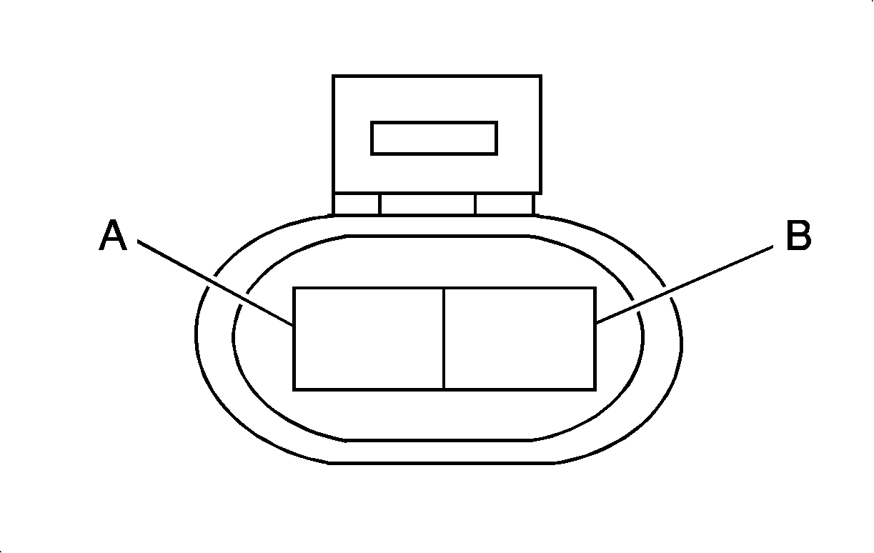
Connector Part Information
|
Terminal Part Information
|
Pin | Wire | Circuit | Function |
|---|---|---|---|
A | 0.5 Blue | 410 | Engine Coolant Temperature Sensor Signal |
B | 0.5 Black-Brown | 2761 | Coolant Temperature Sensor Low Reference |
B34 Engine Coolant Temperature Sensor (LXT)

Connector Part Information
|
Terminal Part Information
|
Pin | Wire | Circuit | Function |
|---|---|---|---|
A | 0.75 Blue | 410 | Engine Coolant Temperature Sensor Signal |
B | 0.5 Black-Brown | 2761 | Coolant Temperature Sensor Low Reference |
B37 Engine Oil Pressure Switch (LXT)
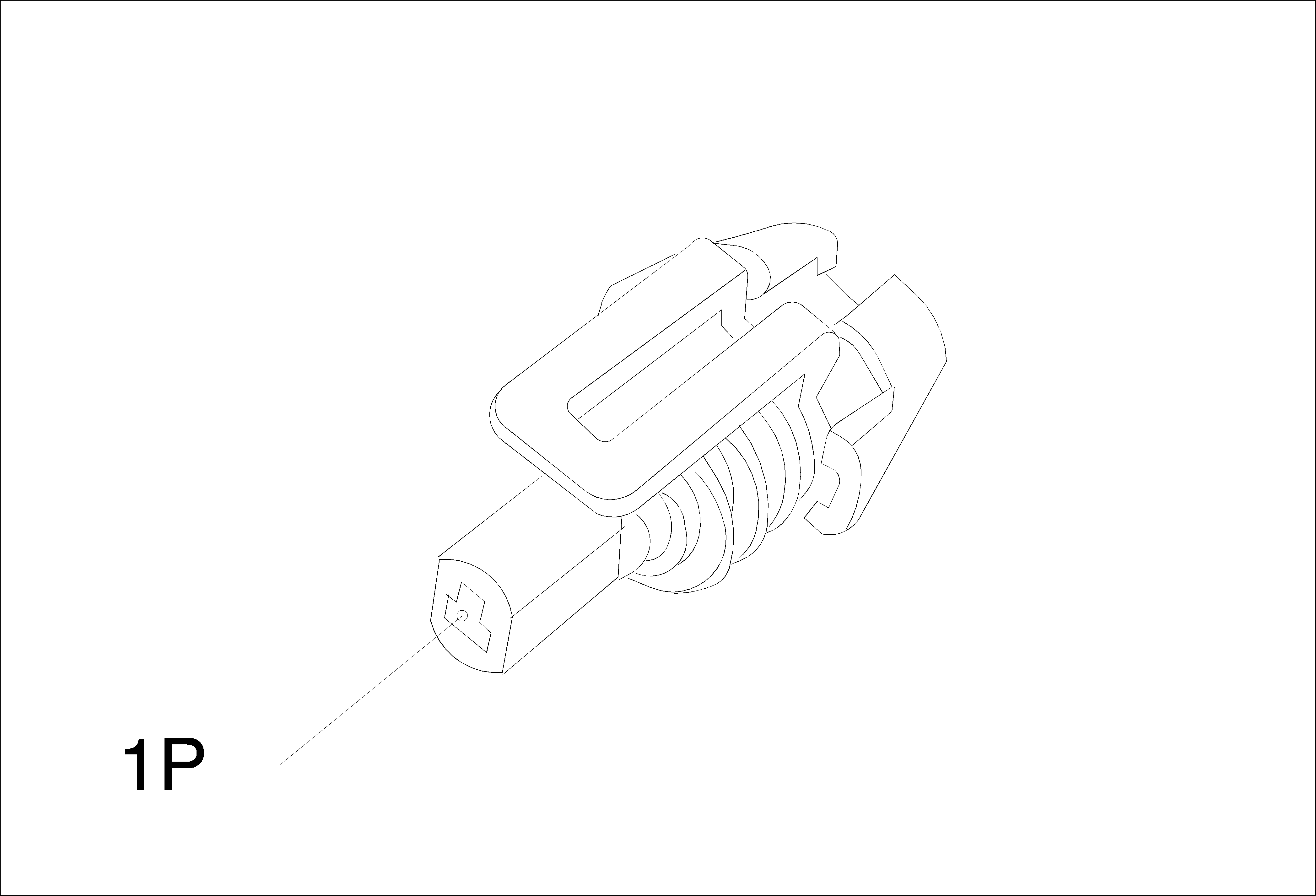
Connector Part Information
|
Terminal Part Information
|
Pin | Wire | Circuit | Function |
|---|---|---|---|
B47B Fuel Rail Pressure Sensor (LLW)

Connector Part Information
|
Terminal Part Information
|
Pin | Wire | Circuit | Function |
|---|---|---|---|
1 | 0.5 Black-Green | 2919 | Fuel Rail Pressure Sensor Low Reference |
2 | 0.5 Blue-White | 2918 | Fuel Rail Pressure Sensor Signal |
3 | 0.5 Brown-Red | 2917 | Fuel Rail Pressure Sensor (5) Volt Reference |
B52A Heated Oxygen Sensor 1 (LXT)
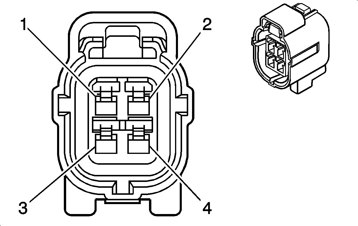
Connector Part Information
|
Terminal Part Information
|
Pin | Wire | Circuit | Function |
|---|---|---|---|
1 | 0.5 Violet-Gray | 3110 | Heated Oxygen Sensor High Signal Bank 1 Sensor (1) |
2 | 0.5 Gray-White | 3113 | Heated Oxygen Sensor Heater Low Control Bank 1 Sensor (1) |
3 | 0.5 White-Black | 3111 | Heated Oxygen Sensor Low Signal Bank 1 Sensor (1) |
4 | 0.5 Violet-Blue | 5292 | Powertrain Main Relay Fused Supply (3) |
0.5 Violet-Blue | 5292 | Powertrain Main Relay Fused Supply (3) | |
0.5 Violet-Blue | 5291 | Powertrain Main Relay Fused Supply (2) |
B52A Heated Oxygen Sensor 1 (LDE/LXV/2H0)

Connector Part Information
|
Terminal Part Information
|
Pin | Wire | Circuit | Function |
|---|---|---|---|
1 | 0.5 Gray-White | 3113 | Heated Oxygen Sensor Heater Low Control Bank 1 Sensor (1) |
2 | 0.5 Violet-Gray | 3110 | Heated Oxygen Sensor High Signal Bank 1 Sensor (1) |
3 | 0.5 Violet-Blue | 5291 | Powertrain Main Relay Fused Supply (2) |
0.5 Violet-Blue | 5291 | Powertrain Main Relay Fused Supply (2) | |
4 | 0.5 Violet-Blue | 5292 | Powertrain Main Relay Fused Supply (3) |
0.5 White-Black | 3111 | Heated Oxygen Sensor Low Signal Bank 1 Sensor (1) |
B52B Heated Oxygen Sensor 2 (LDE/LXV/2H0)

Connector Part Information
|
Terminal Part Information
|
Pin | Wire | Circuit | Function |
|---|---|---|---|
1 | 0.5 Gray-White | 3122 | Heated Oxygen Sensor Heater Low Control Bank 1 Sensor (2) |
2 | 0.5 Violet-Blue | 3120 | Heated Oxygen Sensor High Signal Bank 1 Sensor (2) |
3 | 0.5 Violet-Blue | 5291 | Powertrain Main Relay Fused Supply (2) |
0.5 Violet-Blue | 5291 | Powertrain Main Relay Fused Supply (2) | |
4 | 0.5 White-Yellow | 3121 | Heated Oxygen Sensor Low Signal Bank 1 Sensor (2) |
B55 Hood Ajar Switch

Connector Part Information
|
Terminal Part Information
|
Pin | Wire | Circuit | Function |
|---|---|---|---|
B5LF Wheel Speed Sensor - Left Front

Connector Part Information
|
Terminal Part Information
|
Pin | Wire | Circuit | Function |
|---|---|---|---|
A | 0.5 Gray | 830 | Wheel Speed Sensor Signal Left Front |
B | 0.5 Gray-White | 7064 | Wheel Speed Sensor Control Left Front |
B5LR Wheel Speed Sensor - Left Rear

Connector Part Information
|
Terminal Part Information
|
Pin | Wire | Circuit | Function |
|---|---|---|---|
A | 0.5 Blue | 884 | Wheel Speed Sensor Signal Left Rear |
B | 0.5 Gray-Black | 7127 | Wheel Speed Sensor Control Left Rear |
B5RF Wheel Speed Sensor - Right Front

Connector Part Information
|
Terminal Part Information
|
Pin | Wire | Circuit | Function |
|---|---|---|---|
A | 0.5 Yellow | 872 | Wheel Speed Sensor Signal Right Front |
B | 0.5 Gray-Brown | 7065 | Wheel Speed Sensor Control Right Front |
B5RR Wheel Speed Sensor - Right Rear

Connector Part Information
|
Terminal Part Information
|
Pin | Wire | Circuit | Function |
|---|---|---|---|
A | 0.5 Violet | 882 | Wheel Speed Sensor Signal Right Rear |
B | 0.5 Gray-Yellow | 7128 | Wheel Speed Sensor Control Right Rear |
B66 Intake Air Temperature Sensor (LDE/LXV/2H0)
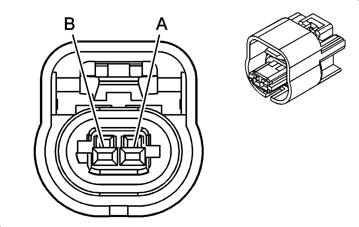
Connector Part Information
|
Terminal Part Information
|
Pin | Wire | Circuit | Function |
|---|---|---|---|
A | 0.5 Brown-Violet | 472 | Intake Air Temperature Sensor Signal |
B | 0.5 Black-Violet | 469 | Manifold Absolute Pressure Sensor Low Reference |
B66 Intake Air Temperature Sensor (LXT)
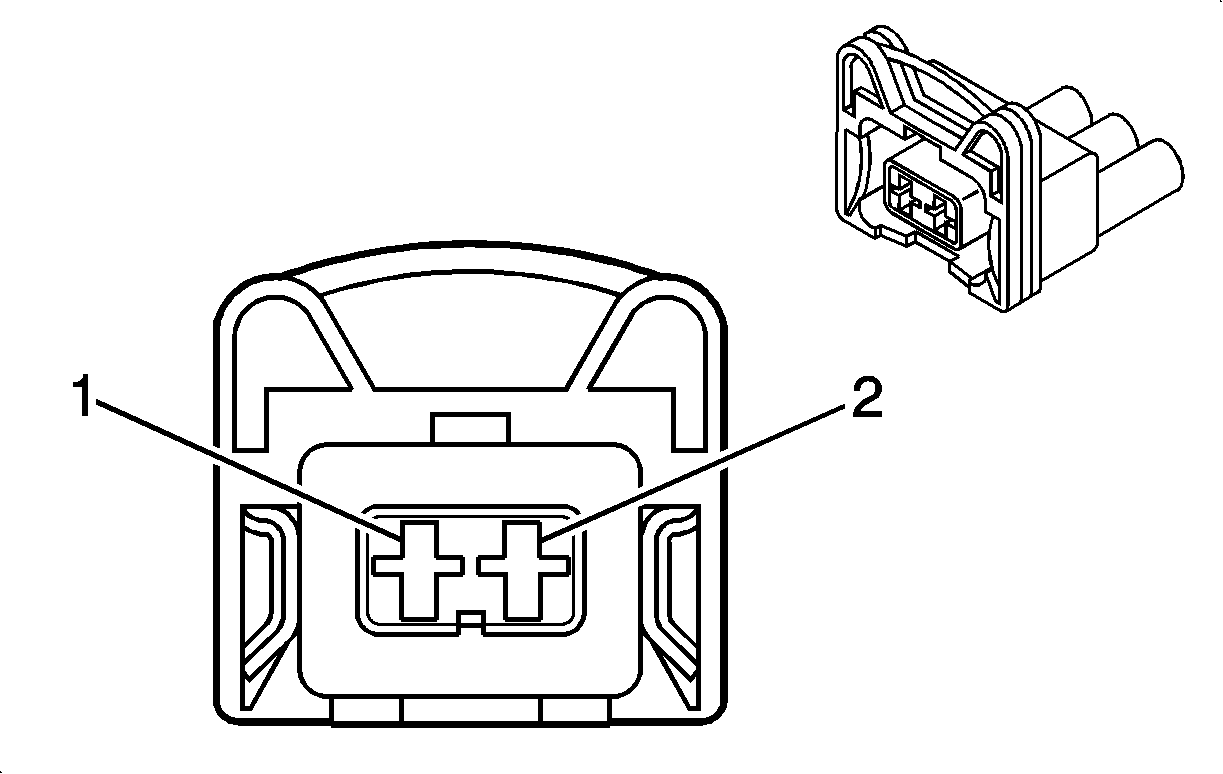
Connector Part Information
|
Terminal Part Information
|
Pin | Wire | Circuit | Function |
|---|---|---|---|
1 | 0.5 Brown-Violet | 472 | Intake Air Temperature Sensor Signal |
2 | 0.5 Black-Violet | 2760 | Intake Air Temperature Sensor Low Reference |
B68 Knock Sensor (LXT)
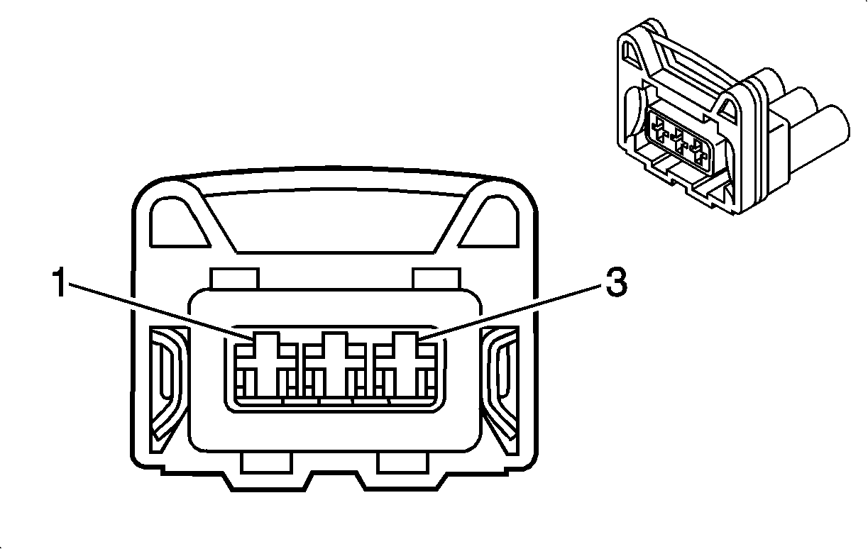
Connector Part Information
|
Terminal Part Information
|
Pin | Wire | Circuit | Function |
|---|---|---|---|
1 | 0.5 White-Gray | 1876 | Knock Sensor Signal (2) |
2 | 0.5 Violet-Gray | 496 | Knock Sensor Signal (1) |
B74 Manifold Absolute Pressure Sensor (LDE/LXV/2H0)
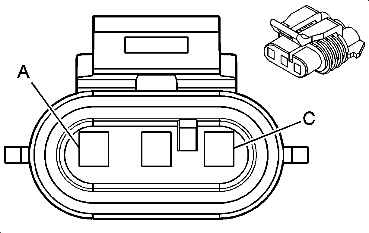
Connector Part Information
|
Terminal Part Information
|
Pin | Wire | Circuit | Function |
|---|---|---|---|
A | 0.5 Black-Green | 469 | Manifold Absolute Pressure Sensor Low Reference |
B | 0.5 Green-White | 432 | Manifold Absolute Pressure Sensor Signal |
C | 0.5 Gray-Red | 2704 | Manifold Absolute Pressure Sensor 5 Volt Reference |
B74 Manifold Absolute Pressure Sensor (LXT)

Connector Part Information
|
Terminal Part Information
|
Pin | Wire | Circuit | Function |
|---|---|---|---|
A | 0.5 Black-Green | 469 | Manifold Absolute Pressure Sensor Low Reference |
B | 0.5 Green-White | 432 | Manifold Absolute Pressure Sensor Signal |
C | 0.5 Gray-Red | 2704 | Manifold Absolute Pressure Sensor 5 Volt Reference |
B9 Air Temperature Sensor - Ambient

Connector Part Information
|
Terminal Part Information
|
Pin | Wire | Circuit | Function |
|---|---|---|---|
C1 Battery
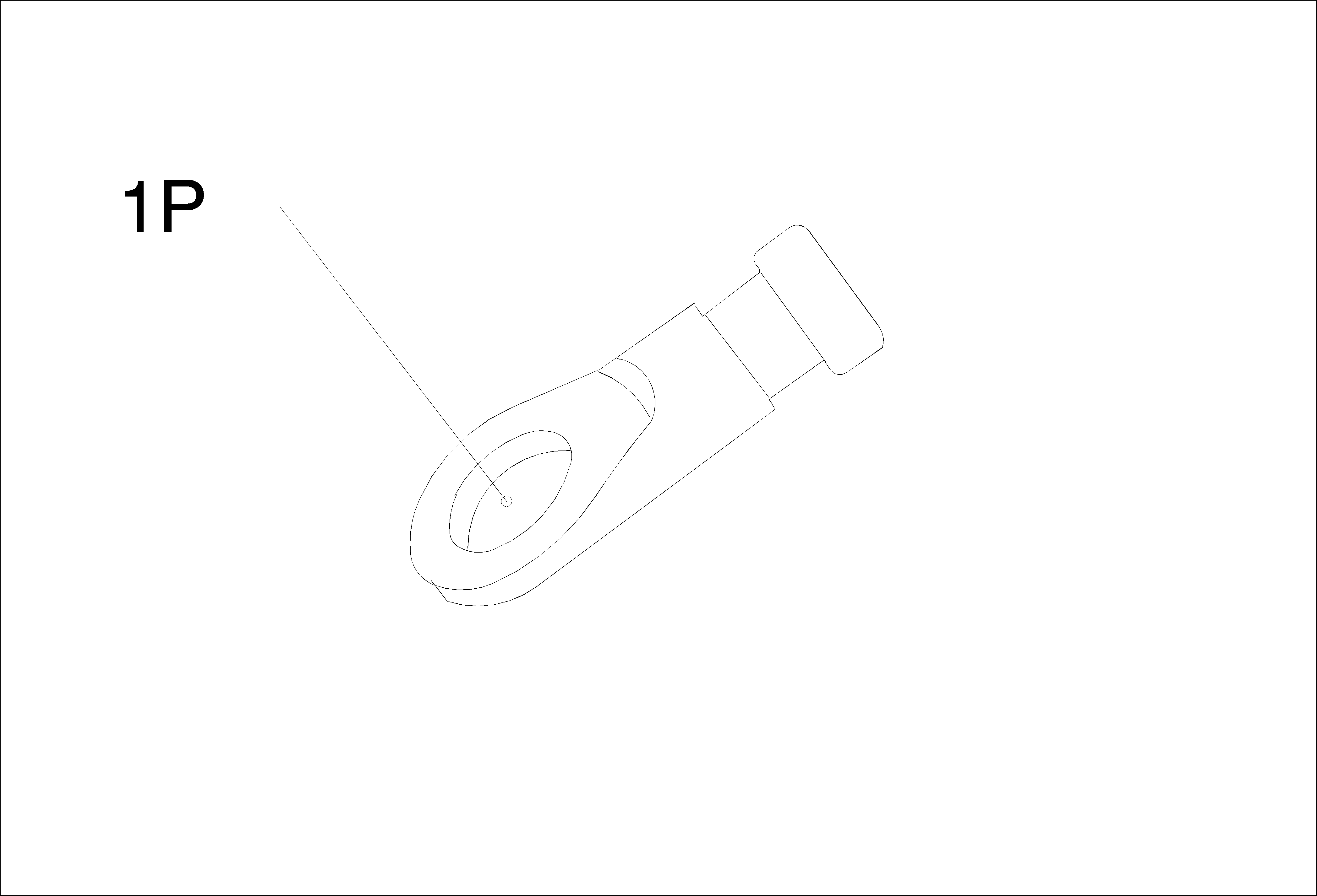
Connector Part Information
|
Terminal Part Information
|
Pin | Wire | Circuit | Function |
|---|---|---|---|
E13L Headlamp Assembly - Left (SAE)
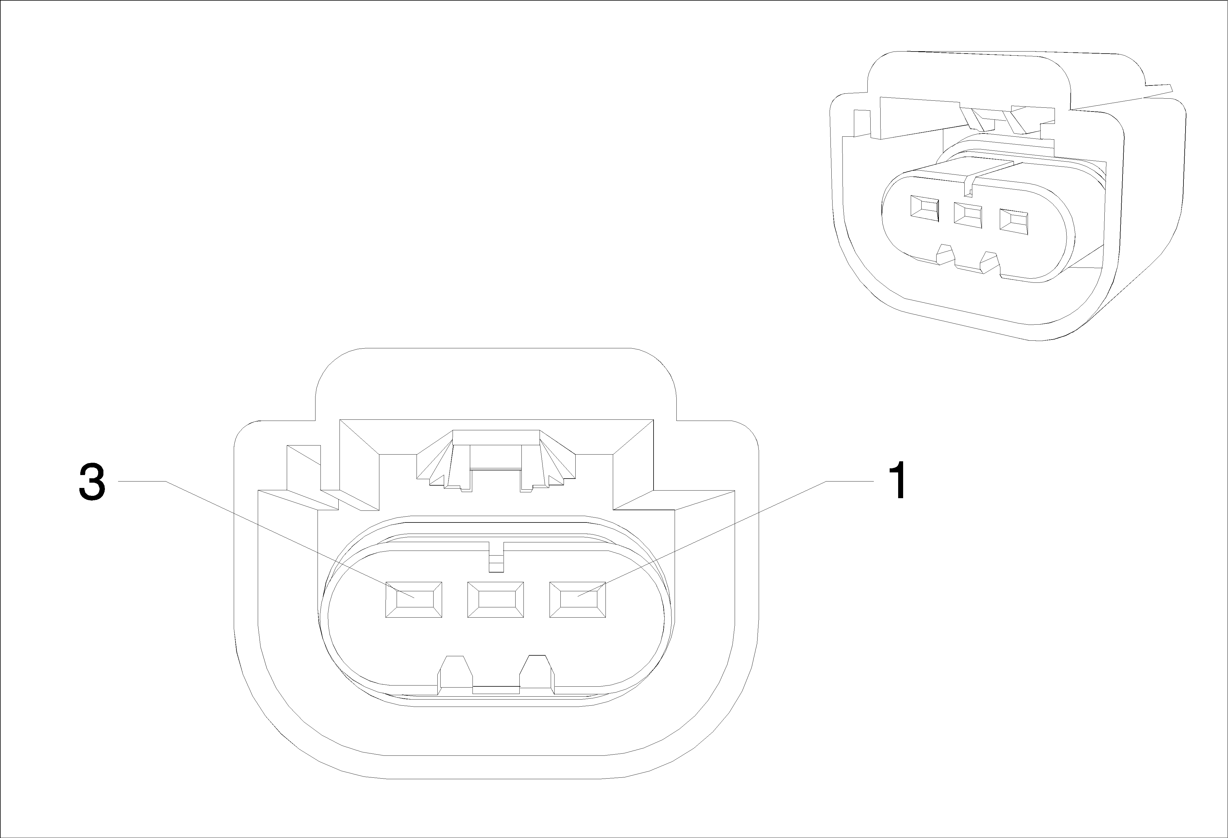
Connector Part Information
|
Terminal Part Information
|
Pin | Wire | Circuit | Function |
|---|---|---|---|
E13R Headlamp Assembly - Right (SAE)

Connector Part Information
|
Terminal Part Information
|
Pin | Wire | Circuit | Function |
|---|---|---|---|
E27 Instrument Panel Compartment Lamp

Connector Part Information
|
Terminal Part Information
|
Pin | Wire | Circuit | Function |
|---|---|---|---|
1 | 1 White-Brown | 6815 | Inadvertent Power Control |
2 | 0.5 Black | 50 | Ground |
E29LF Fog Lamp - Left Front (T96)
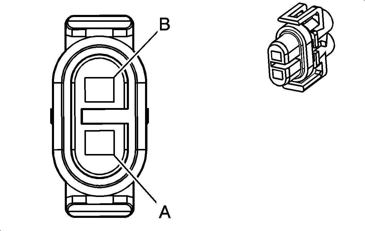
Connector Part Information
|
Terminal Part Information
|
Pin | Wire | Circuit | Function |
|---|---|---|---|
E29LR Fog Lamp - Left Rear

Connector Part Information
|
Terminal Part Information
|
Pin | Wire | Circuit | Function |
|---|---|---|---|
E29RF Fog Lamp - Right Front (T96)

Connector Part Information
|
Terminal Part Information
|
Pin | Wire | Circuit | Function |
|---|---|---|---|
E29RR Fog Lamp - Right Rear
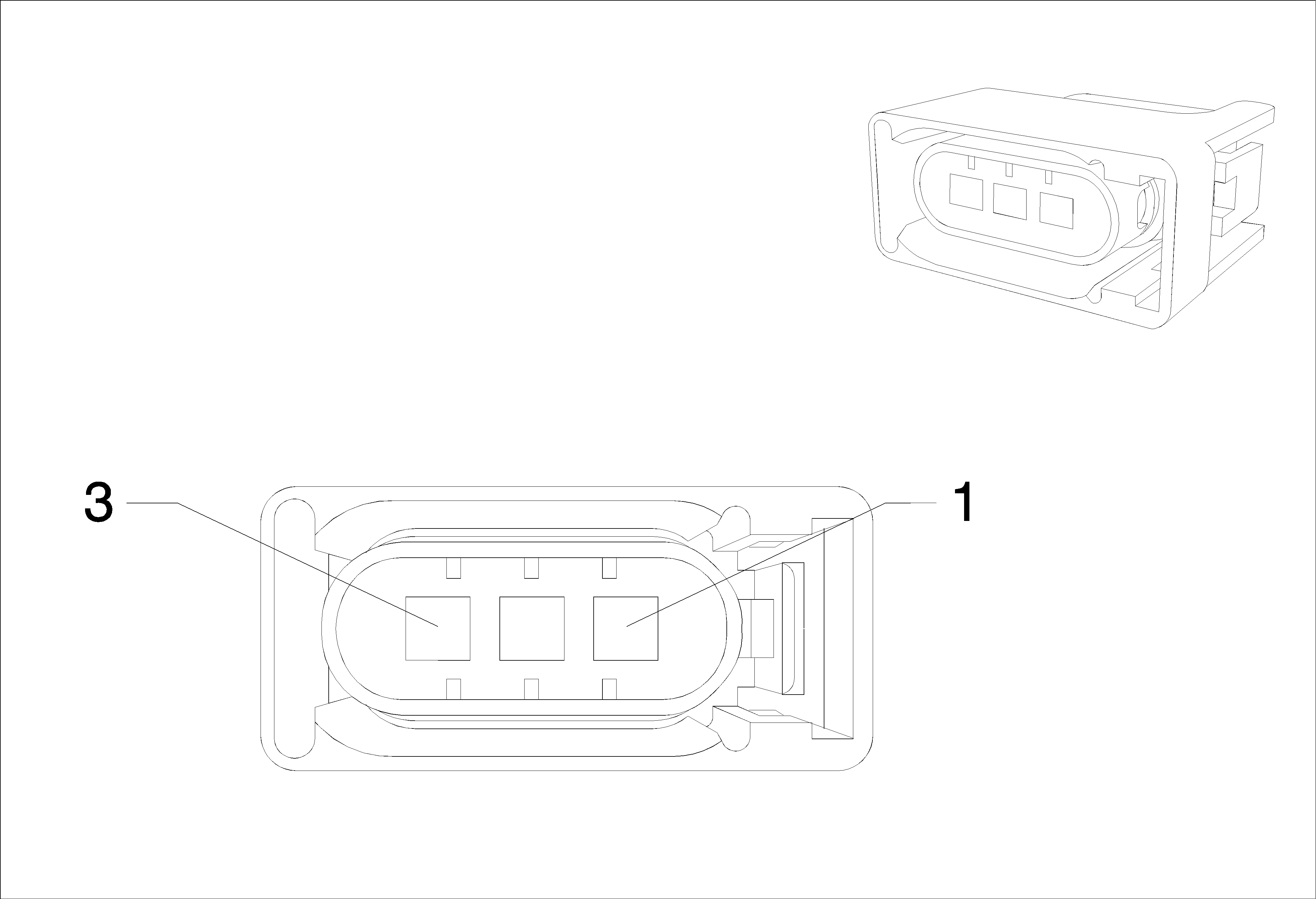
Connector Part Information
|
Terminal Part Information
|
Pin | Wire | Circuit | Function |
|---|---|---|---|
A | 0.75 Black | 50 | Ground |
E2LF Side Marker Lamp - Left Front (SAE)

Connector Part Information
|
Terminal Part Information
|
Pin | Wire | Circuit | Function |
|---|---|---|---|
E2RF Side Marker Lamp - Right Front (SAE)

Connector Part Information
|
Terminal Part Information
|
Pin | Wire | Circuit | Function |
|---|---|---|---|
E40 Electrical Auxiliary Heater X1

Connector Part Information
|
Terminal Part Information
|
Pin | Wire | Circuit | Function |
|---|---|---|---|
1 | 0.5 Violet | 3195 | Auxiliary Heater Control |
2 | 0.5 Violet-Green | 39 | Ignition Voltage |
0.5 Violet-Green | 239 | Ignition Voltage | |
4 | 0.5 Yellow-Green | 3196 | Auxiliary Heater Status Signal |
E40 (X2) Electrical Auxiliary Heater X2

Connector Part Information
|
Terminal Part Information
|
Pin | Wire | Circuit | Function |
|---|---|---|---|
E41 Engine Coolant Thermostat Heater (LDE/2H0)

Connector Part Information
|
Terminal Part Information
|
Pin | Wire | Circuit | Function |
|---|---|---|---|
E4LF Turn Signal Lamp - Left Front (ECE)

Connector Part Information
|
Terminal Part Information
|
Pin | Wire | Circuit | Function |
|---|---|---|---|
E4N Park/Turn Signal Lamp - Left (DOM)
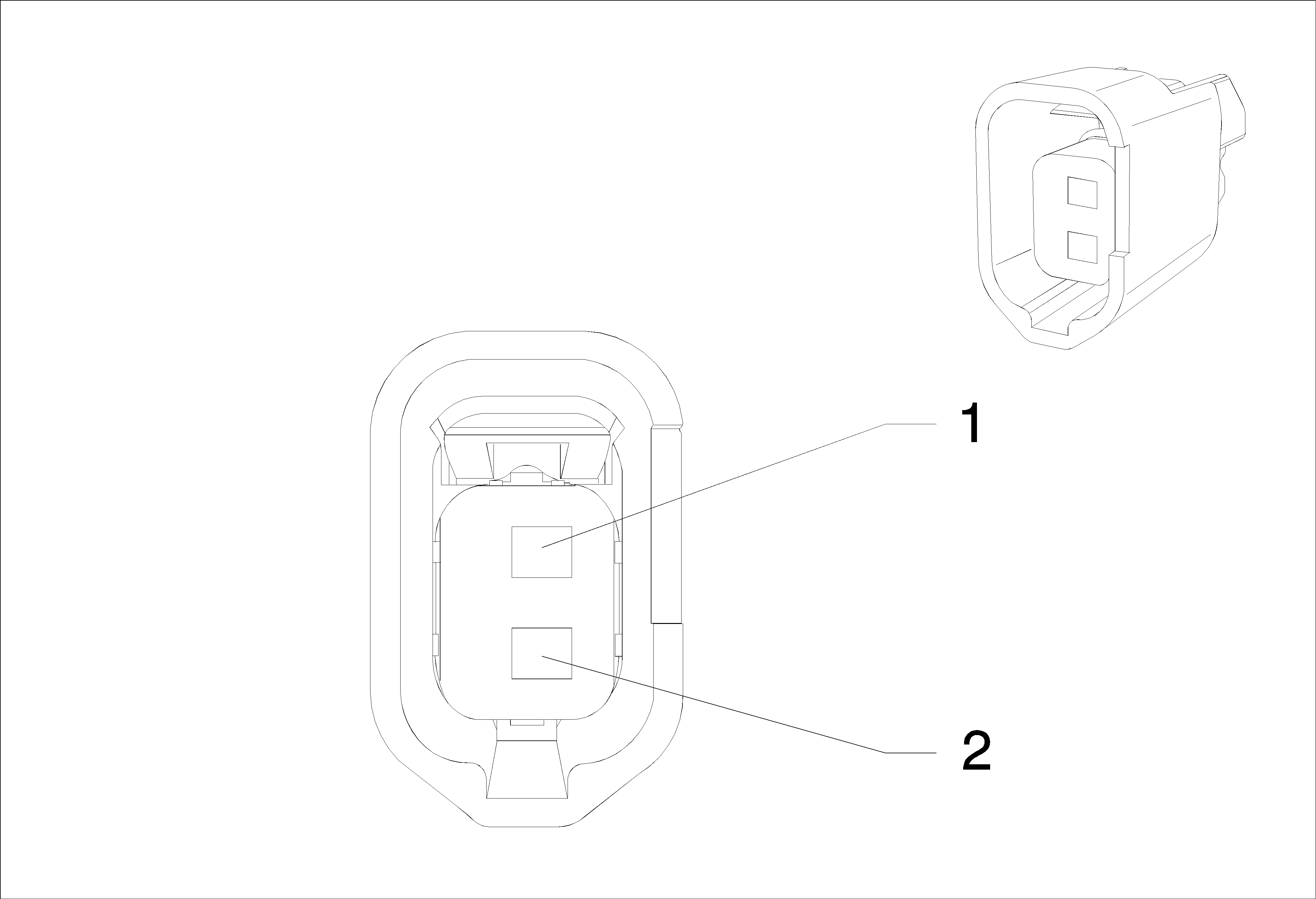
Connector Part Information
|
Terminal Part Information
|
Pin | Wire | Circuit | Function |
|---|---|---|---|
E4P Park/Turn Signal Lamp - Right (DOM)

Connector Part Information
|
Terminal Part Information
|
Pin | Wire | Circuit | Function |
|---|---|---|---|
E4RF Turn Signal Lamp - Right Front (ECE)

Connector Part Information
|
Terminal Part Information
|
Pin | Wire | Circuit | Function |
|---|---|---|---|
E6 Center High Mounted Stop Lamp
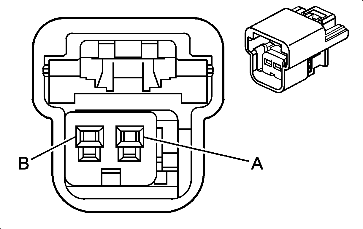
Connector Part Information
|
Terminal Part Information
|
Pin | Wire | Circuit | Function |
|---|---|---|---|
A | 0.5 Violet-White | 5065 | Stop Lamp Relay Coil Control |
B | 0.5 Black | 50 | Ground |
F105L Roof Rail Air Bag - Left
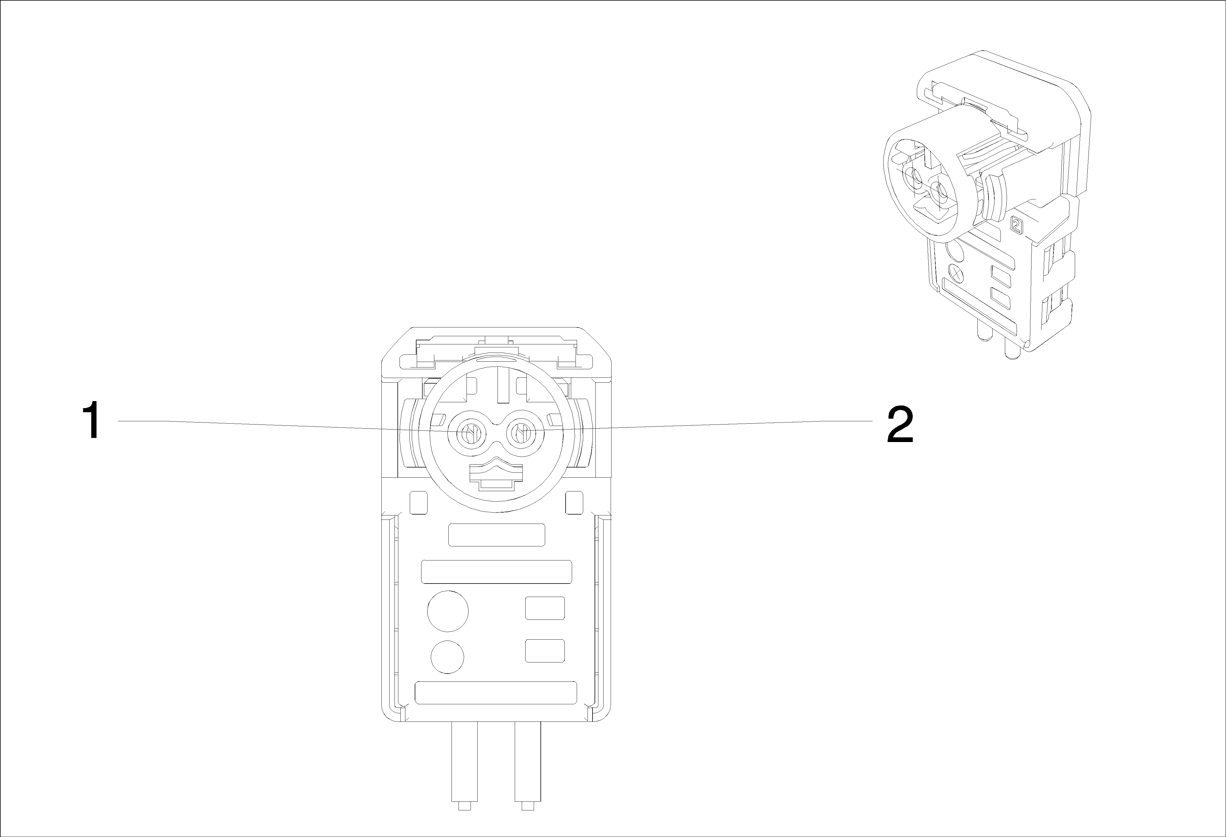
Connector Part Information
|
Terminal Part Information
|
Pin | Wire | Circuit | Function |
|---|---|---|---|
1 | 0.5 Orange-Green | 5019 | Left Front Head Curtain Module High Control |
2 | 0.5 Violet-Orange | 5020 | Left Front Head Curtain Module Low Control |
F105R Roof Rail Air Bag - Right

Connector Part Information
|
Terminal Part Information
|
Pin | Wire | Circuit | Function |
|---|---|---|---|
1 | 0.5 Orange-Gray | 5021 | Right Front Head Curtain Module High Control |
2 | 0.5 White-Orange | 5022 | Right Front Head Curtain Module Low Control |
F112D Seat Belt Pretensioner (Retractor) - Driver

Connector Part Information
|
Terminal Part Information
|
Pin | Wire | Circuit | Function |
|---|---|---|---|
1 | 0.5 Brown-Orange | 2118 | Driver Seat Belt Pretensioner High Control |
2 | 0.5 Orange-Yellow | 2119 | Driver Seat Belt Pretensioner Low Control |
F112P Seat Belt Pretensioner (Retractor) - Passenger

Connector Part Information
|
Terminal Part Information
|
Pin | Wire | Circuit | Function |
|---|---|---|---|
1 | 0.5 Orange-Gray | 2116 | Passenger Seat Belt Pretensioner High Control |
2 | 0.5 Blue-Orange | 2117 | Passenger Seat Belt Pretensioner Low Control |
G10 Cooling Fan Motor (-LLW)

Connector Part Information
|
Terminal Part Information
|
Pin | Wire | Circuit | Function |
|---|---|---|---|
1 | 4 Black | 50 | Ground |
4 Black | 50 | Ground (LXV LDE 2H0) | |
4 Black | 50 | Ground (LXT) | |
2 | 2.5 White-Blue | 409 | Cooling Fan Motor Control (1) |
2.5 White-Blue | 409 | Cooling Fan Motor Control (1) (LXV LDE 2H0) | |
2.5 White-Blue | 409 | Cooling Fan Motor Control (1) (LXT) | |
3 | 2.5 Gray | 532 | Cooling Fan Motor Control (2) (FI) |
2.5 Gray | 532 | Cooling Fan Motor Control (2) (LXV LDE 2H0) | |
2.5 Gray | 532 | Cooling Fan Motor Control (2) (LXT) | |
4 | 4 Yellow | 5358 | Cooling Fan Motor Control (3) (FI) |
4 Yellow | 5358 | Cooling Fan Motor Control (3) (LXV LDE 2H0) | |
4 Yellow | 5358 | Cooling Fan Motor Control (3) (LXT) |
G101 Engine Compartment, Front Left

Connector Part Information
|
Terminal Part Information
|
Pin | Wire | Circuit | Function |
|---|---|---|---|
G103 Engine Compartment, Front Left

Connector Part Information
|
Terminal Part Information
|
Pin | Wire | Circuit | Function |
|---|---|---|---|
G104 Engine Compartment, Front Right

Connector Part Information
|
Terminal Part Information
|
Pin | Wire | Circuit | Function |
|---|---|---|---|
G13 (X1) Generator X1 (LDE/2H0)

Connector Part Information
|
Terminal Part Information
|
Pin | Wire | Circuit | Function |
|---|---|---|---|
G13 (X2) Generator X2 (LXT)

Connector Part Information
|
Terminal Part Information
|
Pin | Wire | Circuit | Function |
|---|---|---|---|
G13 Generator (LLW)

Connector Part Information
|
Terminal Part Information
|
Pin | Wire | Circuit | Function |
|---|---|---|---|
G201 Cross Member, Instrument Panel, Left

Connector Part Information
|
Terminal Part Information
|
Pin | Wire | Circuit | Function |
|---|---|---|---|
G202 Cross Member, Instrument Panel, Behind Radio (Left-Hand Drive)

Connector Part Information
|
Terminal Part Information
|
Pin | Wire | Circuit | Function |
|---|---|---|---|
G202 Cross Member, Instrument Panel, Bbehind Rradio (Right-Hand Drive)

Connector Part Information
|
Terminal Part Information
|
Pin | Wire | Circuit | Function |
|---|---|---|---|
G203 Cross Member, Instrument Panel, Behind Radio

Connector Part Information
|
Terminal Part Information
|
Pin | Wire | Circuit | Function |
|---|---|---|---|
G204 Cross Member, Instrument Panel, Right (Left-Hand Drive)

Connector Part Information
|
Terminal Part Information
|
Pin | Wire | Circuit | Function |
|---|---|---|---|
G204 Cross Member, Instrument Panel, Right (Right-Hand Drive)

Connector Part Information
|
Terminal Part Information
|
Pin | Wire | Circuit | Function |
|---|---|---|---|
G24 Windshield Washer Pump
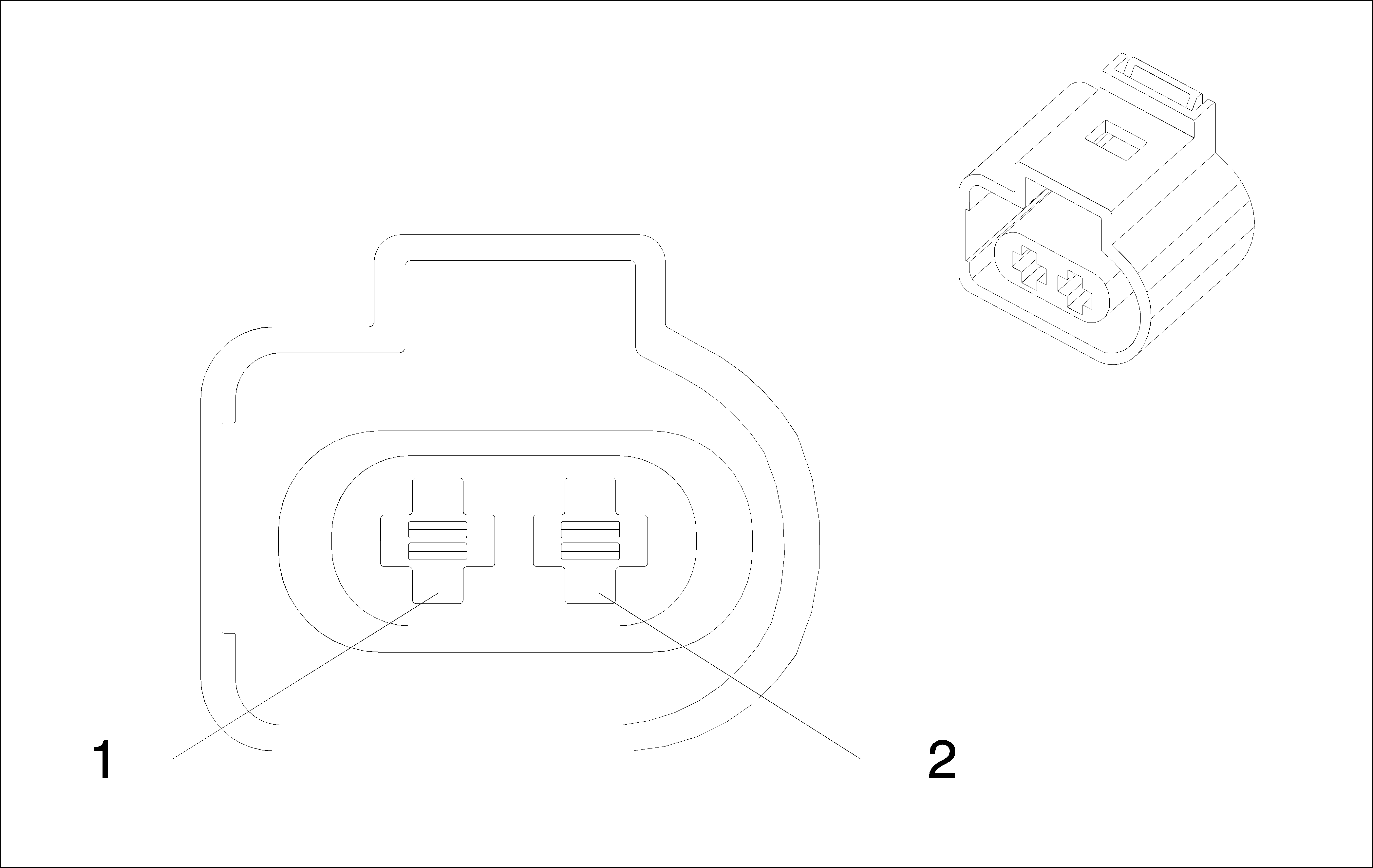
Connector Part Information
|
Terminal Part Information
|
Pin | Wire | Circuit | Function |
|---|---|---|---|
1 | 1 Gray-Violet | 228 | Windshield Washer Pump Control |
2 | 0.5 Black | 50 | Ground |
1 Black | 50 | Ground |
G305 A - Pillar, Left

Connector Part Information
|
Terminal Part Information
|
Pin | Wire | Circuit | Function |
|---|---|---|---|
G307 Tunnel

Connector Part Information
|
Terminal Part Information
|
Pin | Wire | Circuit | Function |
|---|---|---|---|
G308 A - Pillar, Right

Connector Part Information
|
Terminal Part Information
|
Pin | Wire | Circuit | Function |
|---|---|---|---|
G309 Panel Rear, Left

Connector Part Information
|
Terminal Part Information
|
Pin | Wire | Circuit | Function |
|---|---|---|---|
G400 Panel Rear, Right

Connector Part Information
|
Terminal Part Information
|
Pin | Wire | Circuit | Function |
|---|---|---|---|
G401 Panel Rear, Left

Connector Part Information
|
Terminal Part Information
|
Pin | Wire | Circuit | Function |
|---|---|---|---|
G402 Panel Rear, Right

Connector Part Information
|
Terminal Part Information
|
Pin | Wire | Circuit | Function |
|---|---|---|---|
K20 Engine Control Module X1 (LXT)
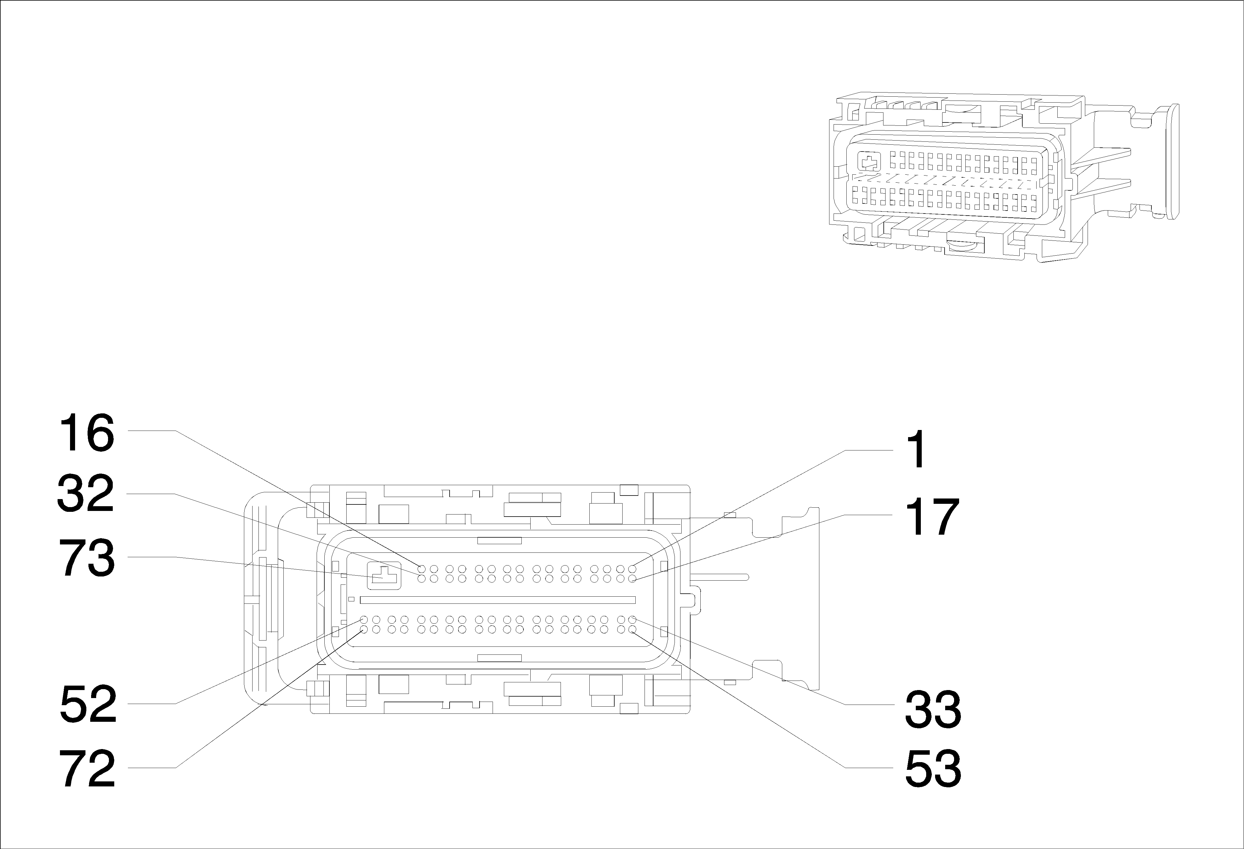
Connector Part Information
|
Terminal Part Information
|
Pin | Wire | Circuit | Function |
|---|---|---|---|
1 | 0.75 Yellow-Violet | 406 | Ignition Control Timing Control (2) |
2 | 0.5 White-Black | 3111 | Heated Oxygen Sensor Low Signal Bank 1 Sensor (1) |
3 | 0.5 Black-Brown | 2752 | Throttle Position Sensor Low Reference (LXT -SAE) |
4 | 0.5 Brown-Red | 2701 | Throttle Position Sensor 5 Volt Reference (LXT -SAE) |
5 | 0.5 Gray-Red | 6109 | Clutch Apply Sensor Voltage Reference |
6 | 0.5 Gray-Red | 2704 | Manifold Absolute Pressure Sensor 5 Volt Reference |
9 | 0.5 Brown-Violet | 472 | Intake Air Temperature Sensor Signal |
10 | 0.5 Violet-Gray | 3110 | Heated Oxygen Sensor High Signal Bank 1 Sensor (1) |
12 | 0.5 Violet-Gray | 496 | Knock Sensor Signal (1) |
13 | 0.5 Gray | 23 | Generator Field Duty Cycle Signal |
14 | 0.5 Gray-White | 3113 | Heated Oxygen Sensor Heater Low Control Bank 1 Sensor (1) |
15 | 0.5 White | 1456 | Exhaust Gas Recirculation Valve Position Signal |
17 | 0.75 White | 423 | Ignition Control Timing Control (1) |
18 | 0.5 Blue-Red | 2702 | Exhaust Gas Recirculation 5 Volt Reference (2) |
19 | 0.5 Black-Violet | 2760 | Intake Air Temperature Sensor Low Reference |
20 | 0.5 Green | 573 | Crankshaft Sensor Signal (1) |
21 | 0.5 White-Black | 1799 | Crankshaft Position Sensor High Resolution Signal |
22 | 0.5 Blue-White | 5375 | Exhaust Gas Recirculation Position Sensor Signal |
24 | 0.5 Black-Brown | 2761 | Coolant Temperature Sensor Low Reference |
26 | 0.5 Brown-Green | 485 | Throttle Position Sensor Signal (1) (LXT -SAE) |
27 | 0.5 Green-White | 432 | Manifold Absolute Pressure Sensor Signal |
28 | 0.5 White-Gray | 1876 | Knock Sensor Signal (2) |
29 | 0.75 Blue | 410 | Engine Coolant Temperature Sensor Signal |
30 | 0.5 Brown | 25 | Charge Indicator Control |
34 | 0.5 Black-Green | 469 | Manifold Absolute Pressure Sensor Low Reference |
35 | 0.5 Black-Gray | 6110 | Clutch Apply Sensor Low Reference (LXT LXT OR LLW) |
0.5 Black-Gray | 6110 | Clutch Apply Sensor Low Reference (LXT/LLW) | |
0.5 Brown | 445 | Oil Pressure Gauge Signal (LLW LXT) | |
0.5 Brown-White | 6110 | Clutch Apply Sensor Low Reference (LXT LDE OR LXV OR 2H0) | |
37 | 0.5 Violet-Black | 5746 | Exhaust Gas Recirculation Valve Motor Low Signal |
38 | 0.5 Yellow | 6111 | Clutch Apply Sensor Signal |
39 | 0.5 Brown-Blue | 486 | Throttle Position Sensor Signal (2) (LXT -SAE) |
40 | 0.5 Brown | 445 | Oil Pressure Gauge Signal (LXT LDE OR LXV OR 2H0) |
0.5 Brown | 445 | Oil Pressure Gauge Signal (LLW LXT) | |
0.5 Brown | 445 | Oil Pressure Gauge Signal (LXT LXT) | |
45 | 0.5 Violet-White | 7060 | Fuel Injector ECM/PCM/VCM Control (LXT -SAE) |
46 | 0.5 Green-Black | 7061 | Fuel Injector ECM/PCM/VCM Control (LXT -SAE) |
56 | 0.5 Yellow-Violet | 633 | Camshaft Position Sensor Signal |
57 | 0.5 Green-Blue | 428 | EVAP Canister Purge Solenoid Control |
59 | 0.5 Brown-White | 5763 | Exhaust Gas Recirculation Valve Sensor Signal |
61 | 0.5 White | 560 | Throttle Relaxer Motor Control (LXT -SAE) |
63 | 0.5 Yellow-White | 1745 | Fuel Injector Control (2) (LXT -SAE) |
64 | 0.5 Brown-Violet | 1746 | Fuel Injector Control (3) (LXT -SAE) |
65 | 0.5 Brown-Violet | 1744 | Fuel Injector Control (1) (LXT -SAE) |
66 | 0.5 Brown-Yellow | 844 | Fuel Injector Control (4) (LXT -SAE) |
67 | 0.5 Gray-Black | 561 | Throttle Relaxer Motor Low Reference (LXT -SAE) |
K33 (X2) HVAC Control Module X2

Connector Part Information
|
Terminal Part Information
|
Pin | Wire | Circuit | Function |
|---|---|---|---|
K36 Inflatable Restraint Sensing and Diagnostic Module X2

Connector Part Information
|
Terminal Part Information
|
Pin | Wire | Circuit | Function |
|---|---|---|---|
13 | 0.5 Orange-Blue | 2137 | Left Front Side Impact Module High Control |
14 | 0.5 Yellow-Orange | 2138 | Left Front Side Impact Module Low Control |
15 | 0.5 Green-Orange | 2136 | Right Front Side Impact Module Low Control |
16 | 0.5 Orange-Yellow | 2135 | Right Front Side Impact Module High Control |
17 | 0.5 Orange-Green | 5019 | Left Front Head Curtain Module High Control |
18 | 0.5 Violet-Orange | 5020 | Left Front Head Curtain Module Low Control |
19 | 0.5 Orange-Green | 2132 | Left Front Side Impact Sensing Module Signal |
20 | 0.5 Black-Orange | 6628 | Left Front Side Impact Sensing Module Low Reference |
21 | 0.5 Black-Orange | 6629 | Right Front Side Impact Sensing Module Low Reference |
22 | 0.5 Brown-Orange | 2134 | Right Front Side Impact Sensing Module Signal |
23 | 0.5 Orange-Yellow | 354 | Left Front Discriminating Sensor Signal |
24 | 0.5 Black-Orange | 5045 | Left Front Discriminating Sensor Low Reference |
25 | 0.5 Black-Orange | 5600 | Right Front Discriminating Sensor Low Reference |
26 | 0.5 Orange-Green | 1409 | Right Front Discriminating Sensor Signal |
27 | 0.5 Orange-Blue | 6620 | Left Middle Side Impact Sensing Module Signal |
28 | 0.5 Black-Orange | 6621 | Left Middle Side Impact Sensing Module Low Reference |
29 | 0.5 Black-Orange | 6625 | Right Middle Side Impact Sensing Module Low Reference |
30 | 0.5 Orange-Violet | 6624 | Right Middle Side Impact Sensing Module Signal |
37 | 0.5 Brown-Orange | 2118 | Driver Seat Belt Pretensioner High Control |
38 | 0.5 Orange-Yellow | 2119 | Driver Seat Belt Pretensioner Low Control |
39 | 0.5 Blue-Orange | 2117 | Passenger Seat Belt Pretensioner Low Control |
40 | 0.5 Orange-Gray | 2116 | Passenger Seat Belt Pretensioner High Control |
41 | 0.5 Orange-Brown | 238 | Driver Seat Belt Switch Signal |
43 | 0.5 Black-Orange | 1363 | Driver Seat Belt Switch Low Reference |
44 | 0.5 Black-Orange | 1361 | Passenger Seat Belt Switch Low Reference |
45 | 0.5 Orange-Violet | 1362 | Passenger Seat Belt Switch Signal |
47 | 0.5 Orange-Brown | 7571 | Passenger Seat Belt Reminder Signal |
53 | 0.5 Orange-Gray | 5021 | Right Front Head Curtain Module High Control |
54 | 0.5 White-Orange | 5022 | Right Front Head Curtain Module Low Control |
K36 Inflatable Restraint Sensing and Diagnostic Module X2
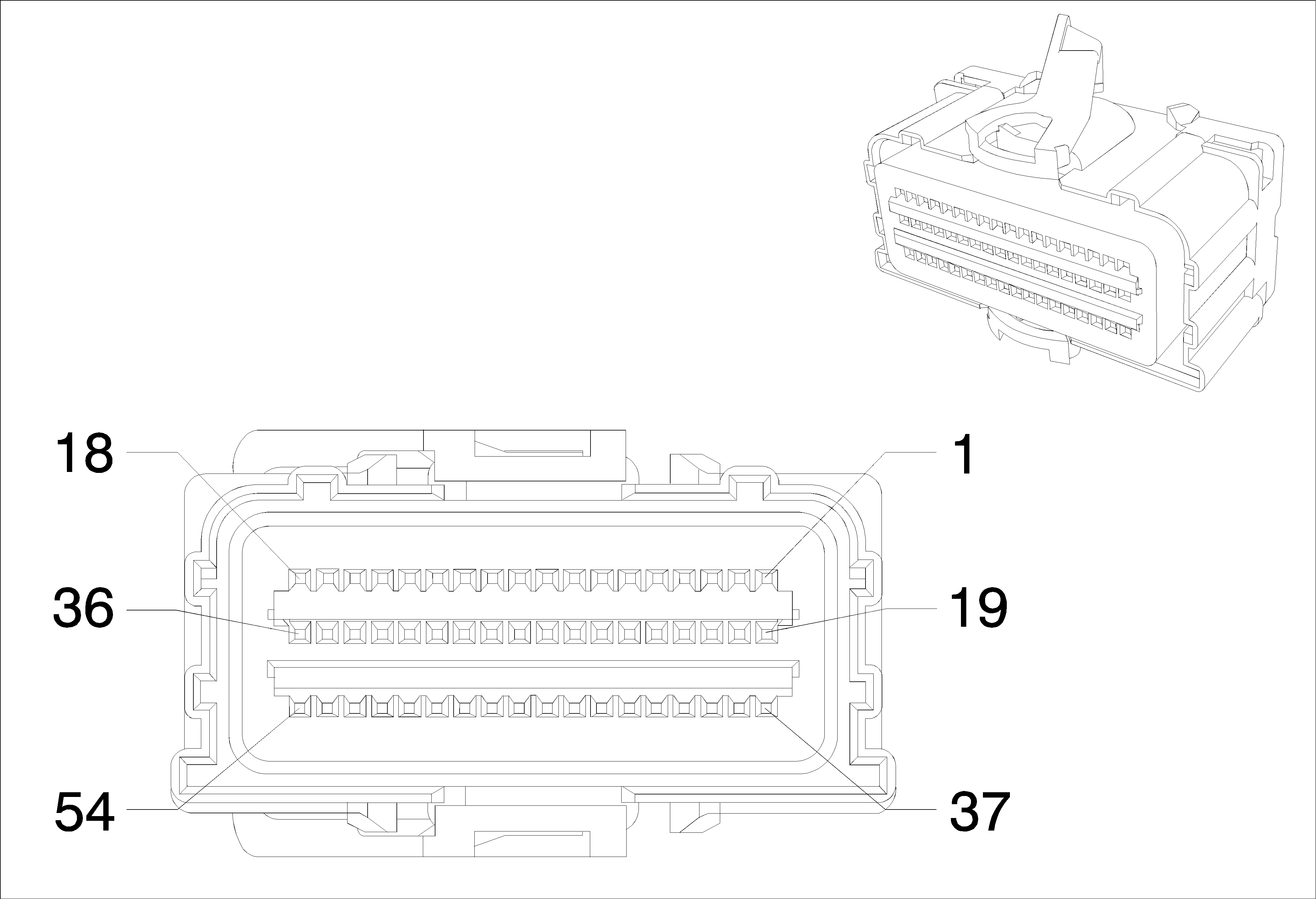
Connector Part Information
|
Terminal Part Information
|
Pin | Wire | Circuit | Function |
|---|---|---|---|
13 | 0.5 Orange-Blue | 2137 | Left Front Side Impact Module High Control |
14 | 0.5 Yellow-Orange | 2138 | Left Front Side Impact Module Low Control |
15 | 0.5 Green-Orange | 2136 | Right Front Side Impact Module Low Control |
16 | 0.5 Orange-Yellow | 2135 | Right Front Side Impact Module High Control |
17 | 0.5 Orange-Green | 5019 | Left Front Head Curtain Module High Control |
18 | 0.5 Violet-Orange | 5020 | Left Front Head Curtain Module Low Control |
19 | 0.5 Orange-Green | 2132 | Left Front Side Impact Sensing Module Signal |
20 | 0.5 Black-Orange | 6628 | Left Front Side Impact Sensing Module Low Reference |
21 | 0.5 Black-Orange | 6629 | Right Front Side Impact Sensing Module Low Reference |
22 | 0.5 Brown-Orange | 2134 | Right Front Side Impact Sensing Module Signal |
23 | 0.5 Orange-Yellow | 354 | Left Front Discriminating Sensor Signal |
24 | 0.5 Black-Orange | 5045 | Left Front Discriminating Sensor Low Reference |
25 | 0.5 Black-Orange | 5600 | Right Front Discriminating Sensor Low Reference |
26 | 0.5 Orange-Green | 1409 | Right Front Discriminating Sensor Signal |
27 | 0.5 Orange-Blue | 6620 | Left Middle Side Impact Sensing Module Signal |
28 | 0.5 Black-Orange | 6621 | Left Middle Side Impact Sensing Module Low Reference |
29 | 0.5 Black-Orange | 6625 | Right Middle Side Impact Sensing Module Low Reference |
30 | 0.5 Orange-Violet | 6624 | Right Middle Side Impact Sensing Module Signal |
37 | 0.5 Brown-Orange | 2118 | Driver Seat Belt Pretensioner High Control |
38 | 0.5 Orange-Yellow | 2119 | Driver Seat Belt Pretensioner Low Control |
39 | 0.5 Blue-Orange | 2117 | Passenger Seat Belt Pretensioner Low Control |
40 | 0.5 Orange-Gray | 2116 | Passenger Seat Belt Pretensioner High Control |
41 | 0.5 Orange-Brown | 238 | Driver Seat Belt Switch Signal |
43 | 0.5 Black-Orange | 1363 | Driver Seat Belt Switch Low Reference |
44 | 0.5 Black-Orange | 1361 | Passenger Seat Belt Switch Low Reference |
45 | 0.5 Orange-Violet | 1362 | Passenger Seat Belt Switch Signal |
47 | 0.5 Orange-Brown | 7571 | Passenger Seat Belt Reminder Signal |
53 | 0.5 Orange-Gray | 5021 | Right Front Head Curtain Module High Control |
54 | 0.5 White-Orange | 5022 | Right Front Head Curtain Module Low Control |
K38 Ultrasonic Intrusion Sensor Module

Connector Part Information
|
Terminal Part Information
|
Pin | Wire | Circuit | Function |
|---|---|---|---|
K41 (X1) Parking Assist Control Module X1

Connector Part Information
|
Terminal Part Information
|
Pin | Wire | Circuit | Function |
|---|---|---|---|
K41 Parking Assist Control Module X2

Connector Part Information
|
Terminal Part Information
|
Pin | Wire color | Circuit | Function |
|---|---|---|---|
1 | 0.5 Yellow-Violet | 2378 | Right Rear Corner Object Sensor Signal |
2 | 0.5 Yellow-White | 2377 | Right Rear Middle Object Sensor Signal |
3 | 0.5 Yellow-Blue | 2376 | Left Rear Middle Object Sensor Signal |
4 | 0.5 Brown-White | 2374 | Object Sensor Control |
5 | 0.5 Yellow | 2375 | Left Rear Corner Object Sensor Signal |
8 | 0.5 Black-Gray | 2379 | Object Sensor Low Reference |
K60 Steering Column Lock Control Module

Connector Part Information
|
Terminal Part Information
|
Pin | Wire | Circuit | Function |
|---|---|---|---|
K61 Sunroof Control Module

Connector Part Information
|
Terminal Part Information
|
Pin | Wire | Circuit | Function |
|---|---|---|---|
K77 (X2) Remote Control Door Lock Receiver X2

Connector Part Information
|
Terminal Part Information
|
Pin | Wire | Circuit | Function |
|---|---|---|---|
K77 (X3) Remote Control Door Lock Receiver X3

Connector Part Information
|
Terminal Part Information
|
Pin | Wire | Circuit | Function |
|---|---|---|---|
K77 (X4) Remote Control Door Lock Receiver X4

Connector Part Information
|
Terminal Part Information
|
Pin | Wire | Circuit | Function |
|---|---|---|---|
K84 Remote Function Receiver Module

Connector Part Information
|
Terminal Part Information
|
Pin | Wire | Circuit | Function |
|---|---|---|---|
1 | 0.5 Gray | 3273 | Remote Function Actuator Return |
2 | 0.5 Blue-White | 3275 | Remote Function Actuator Receive Signal |
3 | 0.5 Yellow-Green | 3274 | Remote Function Actuator Transmit Signal |
4 | 0.5 Gray-White | 3272 | Remote Function Actuator Supply Voltage |
M27 Fuel Door Unlatch Actuator

Connector Part Information
|
Terminal Part Information
|
Pin | Wire | Circuit | Function |
|---|---|---|---|
1 | 0.75 Gray | 295 | Door Lock Actuator Lock Control ( AF8-SAE) |
0.75 Brown-Yellow | 294 | Door Lock Actuator Unlock Control ( -AF8) | |
2 | 0.75 Brown-Yellow | 294 | Door Lock Actuator Unlock Control ( AF8-SAE) |
0.75 Gray | 295 | Door Lock Actuator Lock Control ( -AF8) |
M72 Variable Power Steering Solenoid Valve

Connector Part Information
|
Terminal Part Information
|
Pin | Wire | Circuit | Function |
|---|---|---|---|
1 | 0.5 Brown-Green | 1295 | Variable Effort Steering Solenoid Control |
2 | 0.5 Black-Yellow | 6641 | Variable Effort Steering Solenoid Low Reference |
M74D Window Motor - Driver (AXG)

Connector Part Information
|
Terminal Part Information
|
Pin | Wire | Circuit | Function |
|---|---|---|---|
M75 Windshield Wiper Motor
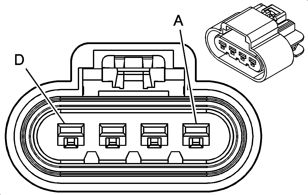
Connector Part Information
|
Terminal Part Information
|
Pin | Wire | Circuit | Function |
|---|---|---|---|
M92 Key Capture Solenoid (w/o ATH+AT)

Connector Part Information
|
Terminal Part Information
|
Pin | Wire | Circuit | Function |
|---|---|---|---|
P14 Passenger Air Bag Disable Indicator
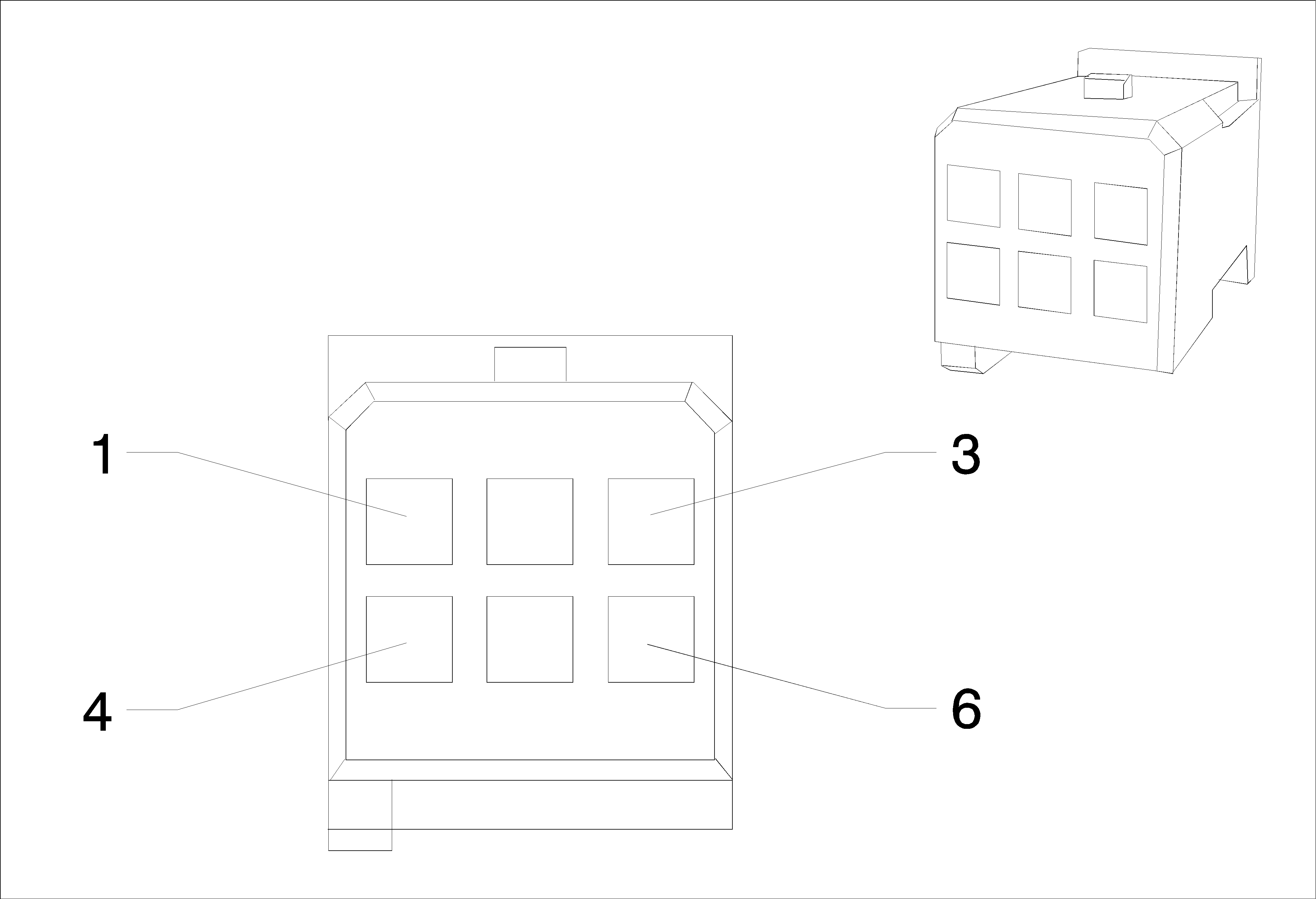
Connector Part Information
|
Terminal Part Information
|
Pin | Wire | Circuit | Function |
|---|---|---|---|
1 | 0.5 Yellow | 6817 | LED Backlight Dimming Control |
2 | 0.35 Blue | 2307 | Passenger Air Bag On Indicator Control |
3 | 0.5 Black | 50 | Ground |
4 | 0.5 Black | 50 | Ground |
5 | 0.35 Green | 2308 | Passenger Air Bag Off Indicator Control |
6 | 0.35 Violet-White | 5234 | Passenger Seat Belt Indicator |
P17 Radio/HVAC Display
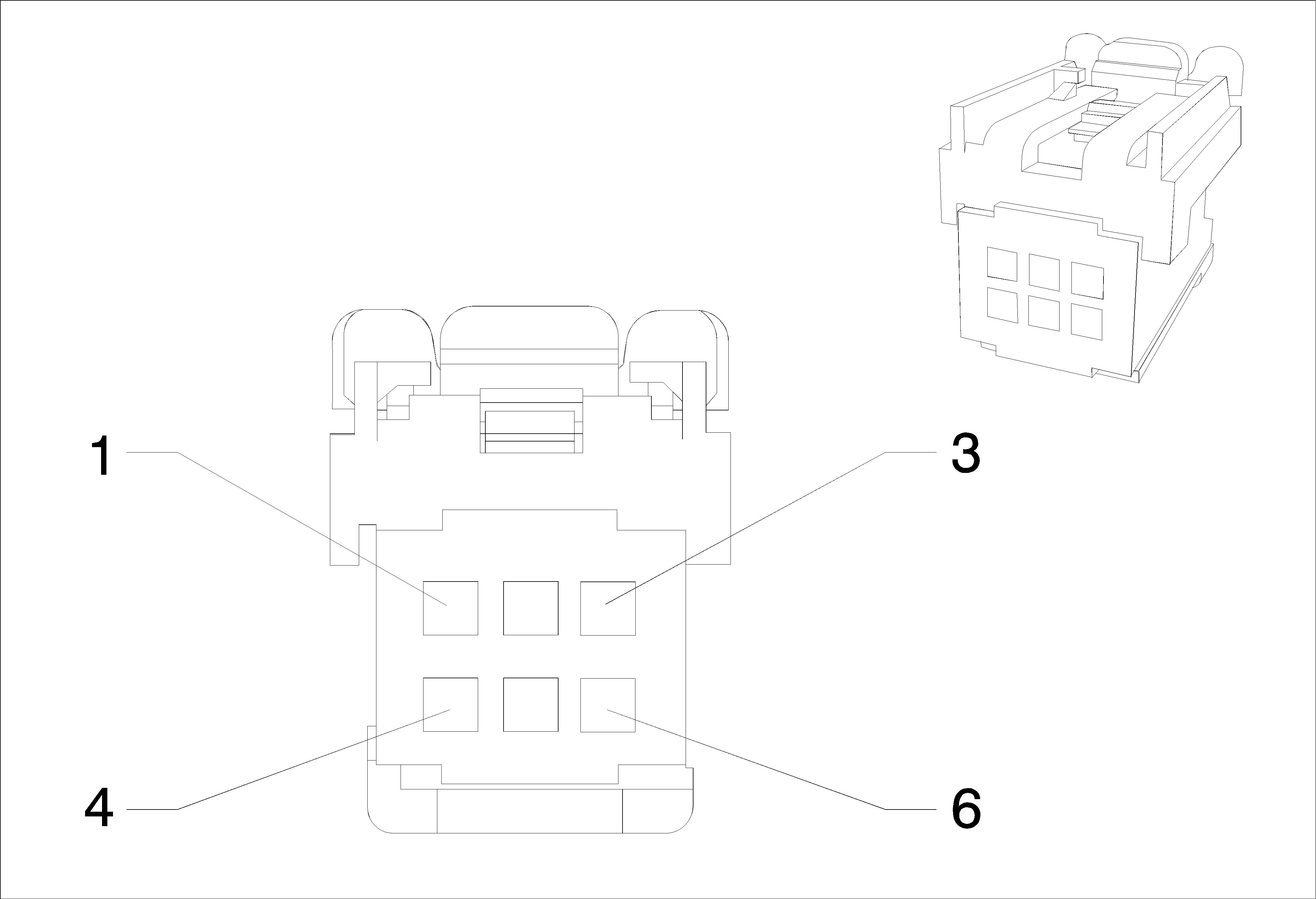
Connector Part Information
|
Terminal Part Information
|
Pin | Wire | Circuit | Function |
|---|---|---|---|
1 | 0.5 Green-Yellow | 7531 | Linear Interconnect Network Bus 9 |
2 | 0.75 Black | 50 | Ground |
3 | 0.75 Red-Yellow | 40 | Battery Positive Voltage |
0.75 Red-Yellow | 240 | Battery Positive Voltage |
P19A Speaker - Center Console

Connector Part Information
|
Terminal Part Information
|
Pin | Wire | Circuit | Function |
|---|---|---|---|
P19H Speaker - Left Front Tweeter

Connector Part Information
|
Terminal Part Information
|
Pin | Wire | Circuit | Function |
|---|---|---|---|
1 | 0.75 Brown-Blue | 118 | Left Front Speaker Signal (-) (1) (LHD UQG) |
0.75 Brown-Blue | 118 | Left Front Speaker Signal (-) (1) (RHD UQG) | |
0.75 Brown-Blue | 118 | Left Front Speaker Signal (-) (1) (RHD UQG) | |
0.75 Blue | 201 | Left Front Speaker (+) (1) (LHD UQG) | |
2 | 0.75 Brown-Blue | 118 | Left Front Speaker Signal (-) (1) (LHD UQG) |
0.75 Blue | 201 | Left Front Speaker (+) (1) (RHD UQG) | |
0.75 Blue | 201 | Left Front Speaker (+) (1) (RHD UQG) | |
0.75 Blue | 201 | Left Front Speaker (+) (1) (LHD UQG) |
P19V Speaker - Right Front Tweeter

Connector Part Information
|
Terminal Part Information
|
Pin | Wire | Circuit | Function |
|---|---|---|---|
1 | 0.75 Yellow | 200 | Right Front Speaker (+) (1) (LHD UQG) |
0.75 Yellow-Black | 117 | Right Front Speaker Signal (-) (1) (LHD UQG) | |
0.75 Yellow-Black | 117 | Right Front Speaker Signal (-) (1) (RHD UQG) | |
0.75 Yellow-Black | 117 | Right Front Speaker Signal (-) (1) (RHD UQG) | |
2 | 0.75 Yellow-Black | 117 | Right Front Speaker Signal (-) (1) (LHD UQG) |
0.75 Yellow | 200 | Right Front Speaker (+) (1) (LHD UQG) | |
0.75 Yellow | 200 | Right Front Speaker (+) (1) (RHD UQG) | |
0.75 Yellow | 200 | Right Front Speaker (+) (1) (RHD UQG) |
P2 Automatic Transmission Shift Lever Position Indicator

Connector Part Information
|
Terminal Part Information
|
Pin | Wire | Circuit | Function |
|---|---|---|---|
P25 Power Sounder
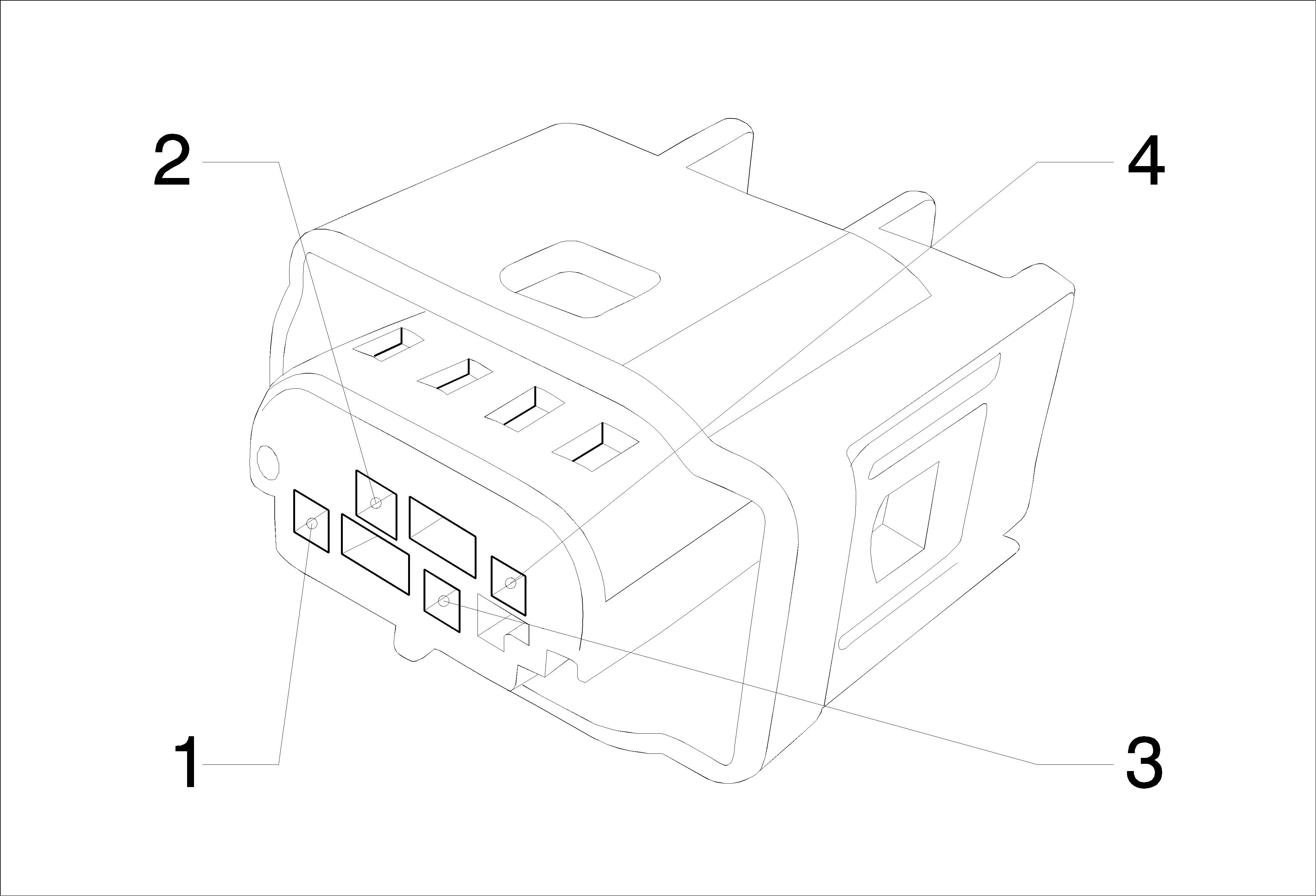
Connector Part Information
|
Terminal Part Information
|
Pin | Wire | Circuit | Function |
|---|---|---|---|
P6 (X1) Clock X1

Connector Part Information
|
Terminal Part Information
|
Pin | Wire | Circuit | Function |
|---|---|---|---|
P9 Driver Information Center Display

Connector Part Information
|
Terminal Part Information
|
Pin | Wire | Circuit | Function |
|---|---|---|---|
Q12 Evaporative Emission (EVAP) Purge Solenoid Valve (LXT)

Connector Part Information
|
Terminal Part Information
|
Pin | Wire | Circuit | Function |
|---|---|---|---|
Q12 Evaporative Emission (EVAP) Purge Solenoid Valve (LXT)

Connector Part Information
|
Terminal Part Information
|
Pin | Wire | Circuit | Function |
|---|---|---|---|
Q14 Exhaust Gas Recirculation (EGR) Valve (LLW)
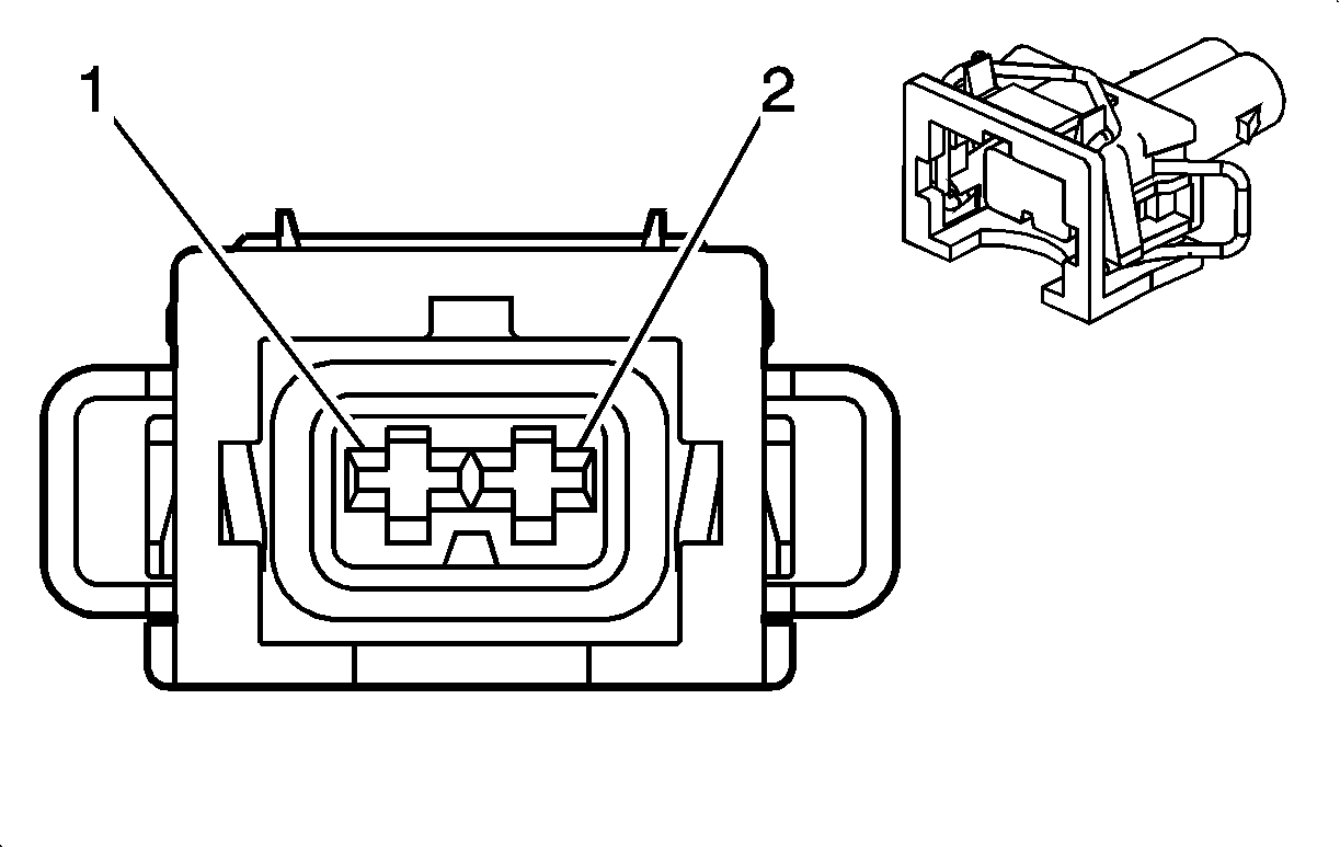
Connector Part Information
|
Terminal Part Information
|
Pin | Wire | Circuit | Function |
|---|---|---|---|
Q17A Fuel Injector 1 (LLW)

Connector Part Information
|
Terminal Part Information
|
Pin | Wire | Circuit | Function |
|---|---|---|---|
1 | 1.5 Blue-White | 5421 | Fuel Injector Control (1) (LLW -SAE) |
2 | 1.5 Brown-Violet | 1744 | Fuel Injector Control (1) (LLW -SAE) |
Q17B Fuel Injector 2 (LLW)

Connector Part Information
|
Terminal Part Information
|
Pin | Wire | Circuit | Function |
|---|---|---|---|
1 | 1.5 Blue-Yellow | 5422 | Fuel Injector Control (2) (LLW -SAE) |
2 | 1.5 Yellow-White | 1745 | Fuel Injector Control (2) (LLW -SAE) |
Q17C Fuel Injector 3 (LLW)

Connector Part Information
|
Terminal Part Information
|
Pin | Wire | Circuit | Function |
|---|---|---|---|
1 | 1.5 Blue-Green | 5423 | Fuel Injector Control (3) (LLW -SAE) |
2 | 1.5 Brown-Violet | 1746 | Fuel Injector Control (3) (LLW -SAE) |
Q17D Fuel Injector 4 (LLW)

Connector Part Information
|
Terminal Part Information
|
Pin | Wire | Circuit | Function |
|---|---|---|---|
1 | 1.5 Blue-Gray | 5425 | Fuel Injector Control (4) (LLW -SAE) |
2 | 1.5 Brown-Yellow | 844 | Fuel Injector Control (4) (LLW -SAE) |
Q18 Fuel Pressure Regulator (LLW)

Connector Part Information
|
Terminal Part Information
|
Pin | Wire | Circuit | Function |
|---|---|---|---|
Q2 A/C Compressor Clutch (LLW)

Connector Part Information
|
Terminal Part Information
|
Pin | Wire | Circuit | Function |
|---|---|---|---|
Q2 A/C Compressor Clutch (LXT)

Connector Part Information
|
Terminal Part Information
|
Pin | Wire | Circuit | Function |
|---|---|---|---|
Q22 Intake Manifold Tuning Solenoid Valve (LXT)

Connector Part Information
|
Terminal Part Information
|
Pin | Wire | Circuit | Function |
|---|---|---|---|
Q38 Throttle Body (LDE/2H0)

Connector Part Information
|
Terminal Part Information
|
Pin | Wire | Circuit | Function |
|---|---|---|---|
Q38 Throttle Body (LLW)

Connector Part Information
|
Terminal Part Information
|
Pin | Wire | Circuit | Function |
|---|---|---|---|
Q38 Throttle Body (LXT)

Connector Part Information
|
Terminal Part Information
|
Pin | Wire | Circuit | Function |
|---|---|---|---|
A | 0.5 White | 560 | Throttle Relaxer Motor Control (LXT -SAE) |
B | 0.5 Gray-Black | 561 | Throttle Relaxer Motor Low Reference (LXT -SAE) |
C | 0.5 Black-Brown | 2752 | Throttle Position Sensor Low Reference (LXT -SAE) |
D | 0.5 Brown-Green | 485 | Throttle Position Sensor Signal (1) (LXT -SAE) |
E | 0.5 Brown-Red | 2701 | Throttle Position Sensor 5 Volt Reference (LXT -SAE) |
F | 0.5 Brown-Blue | 486 | Throttle Position Sensor Signal (2) (LXT -SAE) |
Q6E Camshaft Position Actuator Solenoid Valve - Exhaust (LDE/2H0)

Connector Part Information
|
Terminal Part Information
|
Pin | Wire | Circuit | Function |
|---|---|---|---|
Q6F Camshaft Position Actuator Solenoid Valve - Intake (LDE/2H0)

Connector Part Information
|
Terminal Part Information
|
Pin | Wire | Circuit | Function |
|---|---|---|---|
S13D Door Lock Switch - Driver
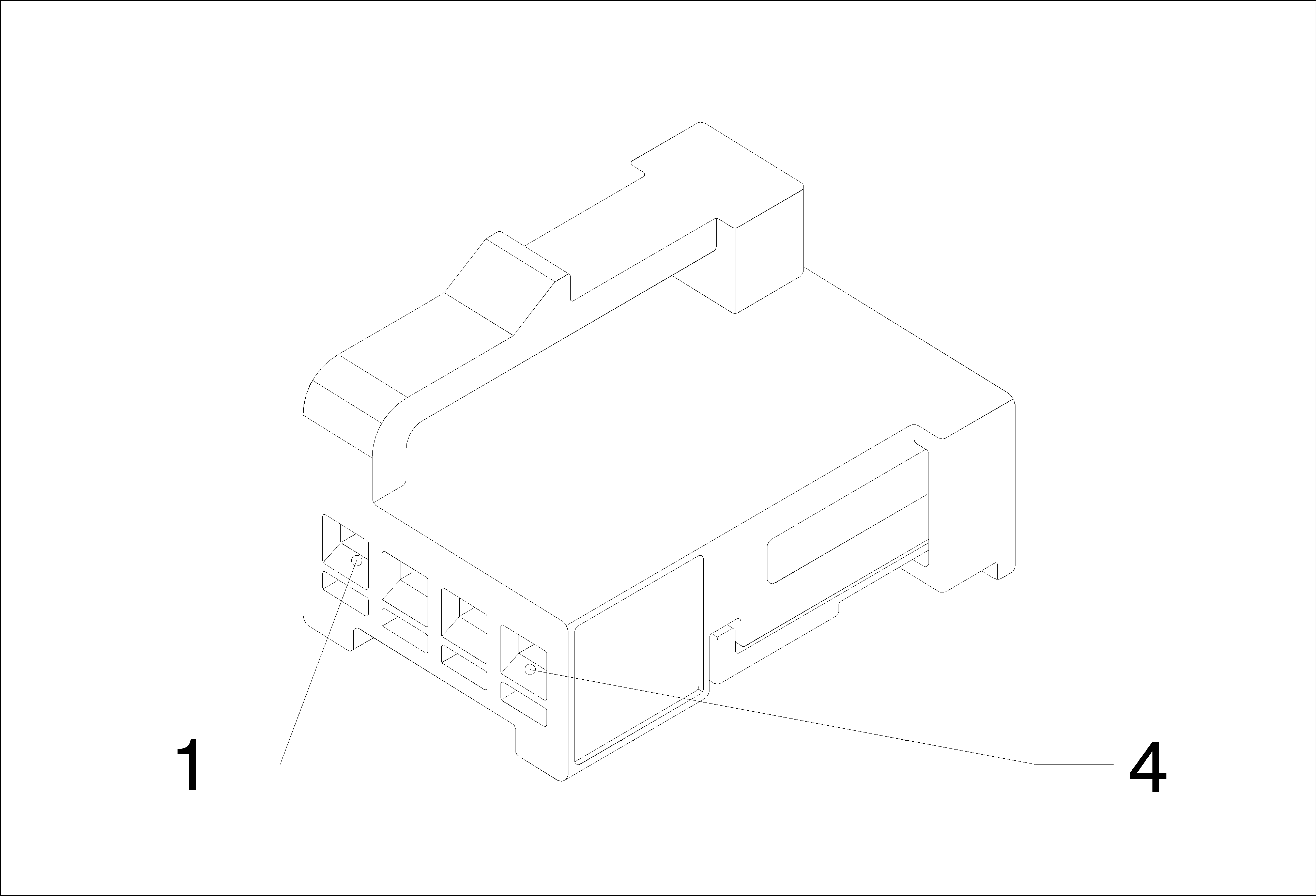
Connector Part Information
|
Terminal Part Information
|
Pin | Wire | Circuit | Function |
|---|---|---|---|
1 | 0.5 Black | 50 | Ground |
0.75 Black | 50 | Ground | |
2 | 0.5 Yellow | 6817 | LED Backlight Dimming Control |
3 | 0.5 Brown-White | 781 | Driver Door Lock Switch Unlock Signal |
4 | 0.5 Brown-Yellow | 780 | Driver Door Lock Switch Lock Signal |
S26 Hazard Lamps Switch
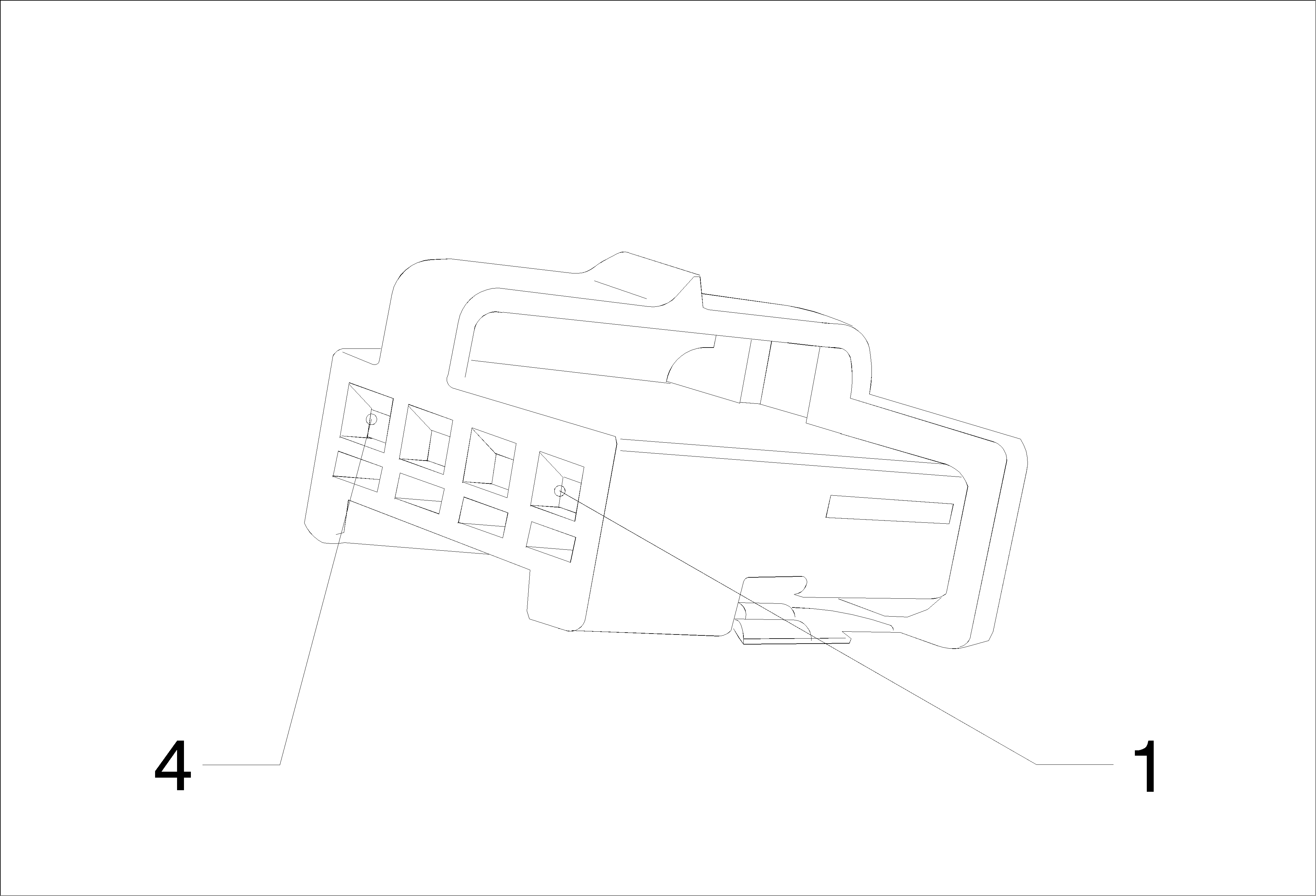
Connector Part Information
|
Terminal Part Information
|
Pin | Wire | Circuit | Function |
|---|---|---|---|
1 | 0.35 Green-White | 111 | Hazard Switch Signal |
2 | 0.35 Blue-Violet | 1717 | Hazard Switch Turn Flasher Control |
3 | 0.5 Black | 50 | Ground |
S3 Automatic Transmission Shift Lever

Connector Part Information
|
Terminal Part Information
|
Pin | Wire | Circuit | Function |
|---|---|---|---|
S30 Headlamp Switch

Connector Part Information
|
Terminal Part Information
|
Pin | Wire | Circuit | Function |
|---|---|---|---|
1 | 0.5 Yellow | 7556 | Lighting Control Switch Reference |
3 | 0.35 Green-Gray | 13 | Headlamp Switch Park Lamp Signal |
4 | 0.35 White-Violet | 103 | Headlamp Switch On Signal |
5 | 0.35 Green-Brown | 306 | Headlamp Switch Headlamps Off Signal Control |
6 | 0.5 Black | 50 | Ground |
7 | 0.5 Yellow | 6817 | LED Backlight Dimming Control |
9 | - - | - | - |
0.5 Brown-Yellow | 239 | Ignition Voltage | |
10 | 0.5 Brown-Yellow | 189 | Headlamp Leveling Motor Control |
12 | 0.5 White-Brown | 7555 | Lighting Control Switch Signal |
S43 Ultrasonic Intrusion Sensor Disable Switch

Connector Part Information
|
Terminal Part Information
|
Pin | Wire | Circuit | Function |
|---|---|---|---|
S52 Mirror Switch

Connector Part Information
|
Terminal Part Information
|
Pin | Wire | Circuit | Function |
|---|---|---|---|
S79D Window Switch - Driver (AEC)

Connector Part Information
|
Terminal Part Information
|
Pin | Wire | Circuit | Function |
|---|---|---|---|
S79LR Window Switch - Left Rear

Connector Part Information
|
Terminal Part Information
|
Pin | Wire | Circuit | Function |
|---|---|---|---|
S79P Window Switch - Passenger

Connector Part Information
|
Terminal Part Information
|
Pin | Wire | Circuit | Function |
|---|---|---|---|
S79RR Window Switch - Right Rear

Connector Part Information
|
Terminal Part Information
|
Pin | Wire | Circuit | Function |
|---|---|---|---|
S88 Sunroof Ventilation Switch

Connector Part Information
|
Terminal Part Information
|
Pin | Wire | Circuit | Function |
|---|---|---|---|
1 | 0.5 Black-Brown | 128 | Sunroof Switch Low Reference |
2 | 0.5 Yellow | 6817 | LED Backlight Dimming Control |
3 | 0.5 Black | 50 | Ground |
4 | 0.5 White-Green | 3031 | Sunroof Vent Switch Signal |
T10E Keyless Entry Antenna - Rear Compartment

Connector Part Information
|
Terminal Part Information
|
Pin | Wire | Circuit | Function |
|---|---|---|---|
1 | 0.5 White-Green | 3556 | Passive Start Interior Antenna 3 Signal Hi |
2 | 0.5 Green | 3557 | Passive Start Interior Antenna 3 Signal Lo |
T3 Audio Amplifier X2

Connector Part Information
|
Terminal Part Information
|
Pin | Wire | Circuit | Function |
|---|---|---|---|
1 | 0.75 Yellow-White | 1860 | Front Center Speaker (+) (UQG) |
2 | 0.75 Blue | 201 | Left Front Speaker (+) (1) (LHD UQG) |
0.75 Blue | 201 | Left Front Speaker (+) (1) (RHD UQG) | |
3 | 0.75 Green | 199 | Left Rear Speaker (+) (LHD UQG) |
0.75 Green | 199 | Left Rear Speaker (+) (RHD UQG) | |
4 | 1 Blue-Gray | 346 | Left/Rear Subwoofer Speaker (+) (UQG) |
6 | 0.75 Yellow | 200 | Right Front Speaker (+) (1) (LHD UQG) |
0.75 Yellow | 200 | Right Front Speaker (+) (1) (RHD UQG) | |
7 | 0.75 White | 46 | Right Rear Speaker (+) (LHD UQG) |
0.75 White | 46 | Right Rear Speaker (+) (RHD UQG) | |
8 | 1 Green-Violet | 1795 | Right Subwoofer Speaker (+) (UQG) |
9 | 0.75 Blue-Yellow | 1960 | Front Center Speaker (-) (UQG) |
10 | 0.75 Brown-Blue | 118 | Left Front Speaker Signal (-) (1) (LHD UQG) |
0.75 Brown-Blue | 118 | Left Front Speaker Signal (-) (1) (RHD UQG) | |
11 | 0.75 Green-Black | 116 | Left Rear Speaker Signal (-) (LHD UQG) |
0.75 Green-Black | 116 | Left Rear Speaker Signal (-) (RHD UQG) | |
12 | 1 Green-Black | 1794 | Left/Rear Subwoofer Speaker (-) (UQG) |
14 | 0.75 Yellow-Black | 117 | Right Front Speaker Signal (-) (1) (LHD UQG) |
0.75 Yellow-Black | 117 | Right Front Speaker Signal (-) (1) (RHD UQG) | |
15 | 0.75 Blue-Black | 115 | Right Rear Speaker Signal (-) (LHD UQG) |
0.75 Blue-Black | 115 | Right Rear Speaker Signal (-) (RHD UQG) | |
16 | 1 Gray-Black | 315 | Right Subwoofer Speaker (-) (UQG) |
T3 Audio Amplifier X3
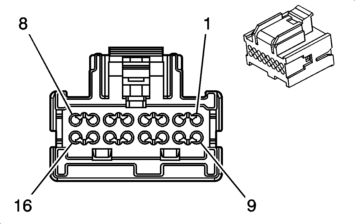
Connector Part Information
|
Terminal Part Information
|
Pin | Wire | Circuit | Function |
|---|---|---|---|
1 | 0.35 Blue | 511 | Left Front Low Level Audio Signal |
2 | 0.35 Yellow | 512 | Right Front Low Level Audio Signal |
3 | 0.35 Green-Black | 599 | Left Rear Low Level Audio Signal |
4 | 0.35 Brown-White | 546 | Right Rear Low Level Audio Signal |
9 | 0.35 Brown-Blue | 1947 | Left Front Low Level Audio (-) |
10 | 0.35 Blue-Brown | 1546 | Front Low Level Audio (-) |
11 | 0.35 Brown-Violet | 1999 | Left Rear Low Level Audio (-) |
12 | 0.35 Blue-Black | 1946 | Right Rear Low Level Audio (-) |
T8 Ignition Coil (LXT)

Connector Part Information
|
Terminal Part Information
|
Pin | Wire | Circuit | Function |
|---|---|---|---|
