Special Tools
EN 6015 Plug
For equivalent regional tools, refer to Special Tools.
Removal Procedure
- Open the hood.
- Disconnect the battery. Refer to Battery Negative Cable Disconnection and Connection.
- Drain the fuel tank. Refer to Fuel Tank Draining.
- Remove the right rear tire and wheel assembly. Refer to Tire and Wheel Removal and Installation.
- Raise the vehicle by its half height. Refer to Lifting and Jacking the Vehicle.
- Install the rear wheel housing liner panel. Refer to Rear Wheelhouse Panel Liner Replacement.
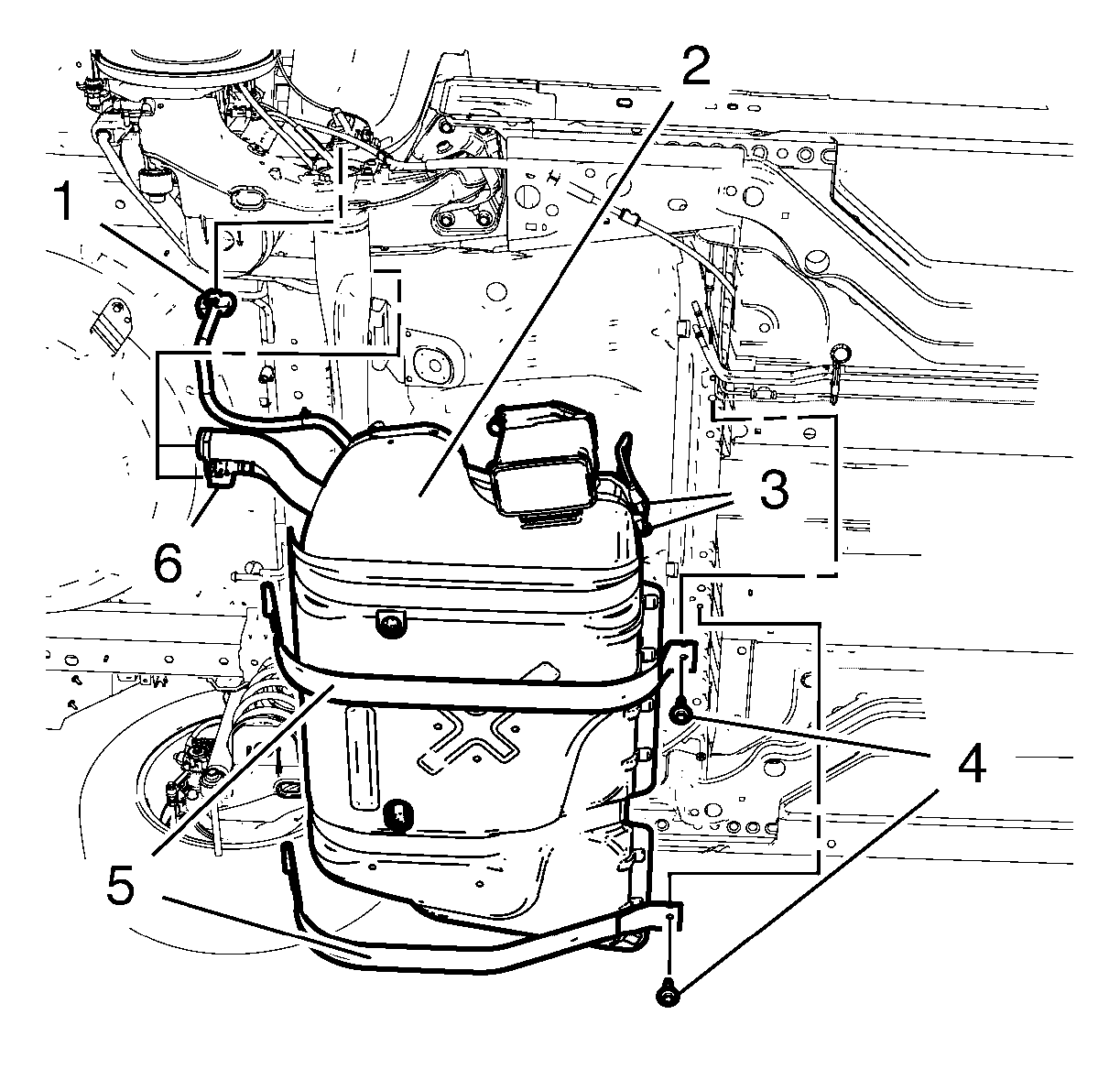
- Disconnect the to fuel tank harness inline connector (1).
- Raise the vehicle by its half height.
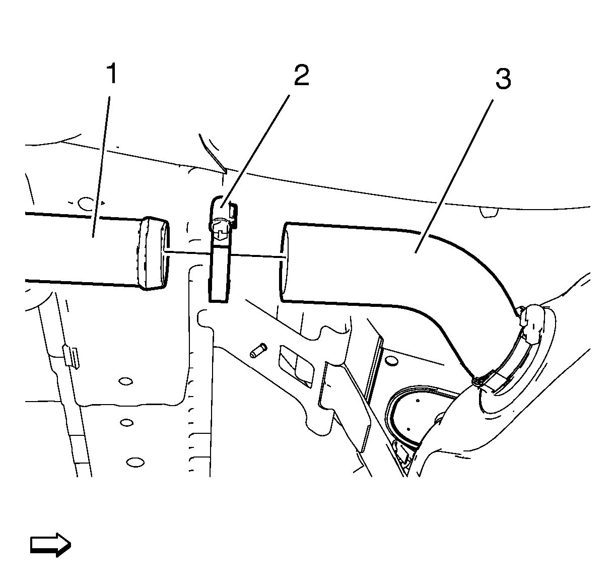
- Remove the clamp (2).
- Remove the fuel tank filler hose (3) from the fuel tank filler pipe (1).
- Disconnect the fuel tank filler vent pipe connector (6).
- Install the EN 6015 plug into the fuel tank vent pipe.
- Disconnect the 2 fuel tank vent pipe connector (3).
- Install the EN 6015 plug into the 2 fuel tank vent pipes.
- Place a suitable adjustable jack under the fuel tank.
- Remove the 2 fuel tank strap bolts (4).
- Remove the 2 fuel tank straps (5).
- Remove fuel tank.
Warning: Unless directed otherwise, the ignition and start switch must be in the OFF or LOCK position, and all electrical loads must be OFF before servicing any electrical component. Disconnect the negative battery cable to prevent an electrical spark should a tool or equipment come in contact with an exposed electrical terminal. Failure to follow these precautions may result in personal injury and/or damage to the vehicle or its components.


Warning: Do not breathe the air through the EVAP component tubes or hoses. The fuel vapors inside the EVAP components may cause personal injury.

Warning: To help avoid personal injury, always use jack stands when you are working on or under any vehicle that is supported only by a jack.
Caution: When you are jacking or lifting a vehicle at the frame side rails or other prescribed lift points, be certain that the lift pads do not contact the catalytic converter, the brake pipes or the fuel lines. If such contact occurs, vehicle damage or unsatisfactory vehicle performance may result.
Note: Two mechanics required.
Note: Retract jack.
Installation Procedure
- Install fuel tank.
- Install the 2 fuel tank straps (5).
- Install the 2 fuel tank strap bolts (4).
- Remove the EN 6015 plug from the 2 fuel tank vent pipes.
- Connect the 2 fuel tank vent pipe connector (3).
- Remove the EN 6015 plug from the fuel tank vent pipe.
- Connect the fuel tank filler vent pipe connector (6).
- Install the fuel tank filler hose (3) to the fuel tank filler pipe (1).
- Install the clamp (2).
- Lower the vehicle by its half height.
- Connect the to fuel tank harness inline connector (1).
- Install the rear wheel housing liner panel. Refer to Rear Wheelhouse Panel Liner Replacement.
- Lower the vehicle by its half height.
- Install the right rear tire and wheel assembly. Refer to Tire and Wheel Removal and Installation.
- Connect the battery. Refer to Battery Negative Cable Disconnection and Connection.
- Close the hood.

Note: Two mechanics required.
Note: Extend jack.


