SERVICE MANUAL UPDATE-SEC. 6E3 CHART A-5 CODES 12,13 & 14

Model and Year: 1990 S CAR WITH 1.6L GSI (VIN CODE 5) ENGINE
This bulletin serves to revise Chart A-5, Code 12 and/or 13, and Code 14 Facing Page and Chart in Section 6E3-A "Driveability And Emissions" in the 1990 Geo Prizm 1.6L GSI (VIN 5) "S" Carline (PORT) Service Manual.
The title block on Pages 6E3-A-1, 6E3-A-26, and 6E3-A-27 are incorrectly labeled. The malfunction Code 12 and 13 is incorrect. Code 12 and 13 should read: Code 12 and/or 13. The attached pages reflect the correct labeling of the malfunction codes and the table of contents page at the beginning of Section 6E3-A.
Revised pages are listed below:
Page 6E3-A-1-Table of Contents Page 6E3-A-16-Chart A-5 facing page Page 6E3-A-17 -Chart A-5 chart Page 6E3-A-26 -Code 12 and/or 13 facing page Page 6E3-A-27 -Code 12 and/or 13 chart Page 6E3-A-28 -Code 14 facing page Page 6E3-A-29 -Code 14 chart
SECTION A 1.6L (VIN 5) "S" CARLINE (PORT)
DIAGNOSTIC CIRCUIT CHECK
The "Diagnostic Circuit Check" verifies that the engine control system is functioning correctly. Special considerations to observe while performing the "Diagnostic Circuit Check" are:
Blocking Drive Wheels
The vehicle drive wheels should always be blocked while checking the system.
Cold Oxygen Sensor
The system oxygen sensor may cool off after only a short period of operation at idle. This will cause the system to enter "Open Loop" operation. run the engine at part throttle until "Closed Loop" operation is restored.
BASIC PROCEDURE
If the basic information on using the diagnostic procedures contained in this section has not been reviewed, refer to the introduction of this section.
SECTION A ENGINE COMPONENTS/WIRING DIAGRAMS/DIAGNOSTIC CHARTS
Engine Component Locations...................... Page A-2 ECM Wiring Diagram (i of 4)..................... Page A-3 ECM Connector Terminal End View ................ Page A-7 Diagnostic Code Table........................... Page A-8 Diagnostic Circuit Check........................ Page A-9 No "Check Engine" Light - Chart A-1............. Page A-10 "Check Engine" Light Won't Flash "ON"........... Page A-12 Steady - Chart A-2 Engine Cranks But Will Not Run - Chart A-3.......Page A-14 Engine Cranks But Wil I Not Run (Fuel System.... Page A-16 Electrical Test) - Chart A-5 Fuel System Pressure Test - Chart A-7........... Page A-18 (1 of 3) Cold Start injector Valve - Chart A-9............Page A-24 Code 12 and/or 13 No Rpm Signal (No Signal...... Page A-26 for 2 Seconds) Code 14 Ignition Signal Circuit (No Signal)..... Page A-28 Code 21 Oxygen (02) Sensor Circuit (Heated)..... Page A-30 (Open/Shorted Circuit) Code 22 Coolant Temperature Sensor (CTS) Circuit.Page A-32 (Open or Shorted Circuit) Code 24 Manifold Air Temperature (MAT) Sensor....Page A-34 Circuit (Low Temperature indicated) Code 25 Oxygen (02) Sensor Circuit.............. Page A-36 (Lean Exhaust Indicated) Code 26 Oxygen (02) Sensor Circuit.............. Page A-38 (Rich Exhaust Indicated) Code 27 Sub Oxygen (02) Sensor Circuit.......... Page A-40 (Open/Shorted Circuit) (California Only) Code 31 Mass Air Flow (MAF) Sensor...............Page A-42 (Short Circuit) Code 41 Throttle Position Sensor (TPS).......... Page A-44 (Open or Short) Code 42 Vehicle Speed Sensor (VSS) Circuit...... Page A-46 Code 43 No Crank Signal (No Signal From........ Page A-48 Starter) Code 51 No A/C Signal............................Page A-50 Code 52 Knock Sensor Signal (Open or Short)..... Page A-52 Code 53 Knock Control Signal (Faulty ECM)........Page A-55 Code 71 EGR Gas Temperature Sensor Circuit.......Page A-56 (California Only)
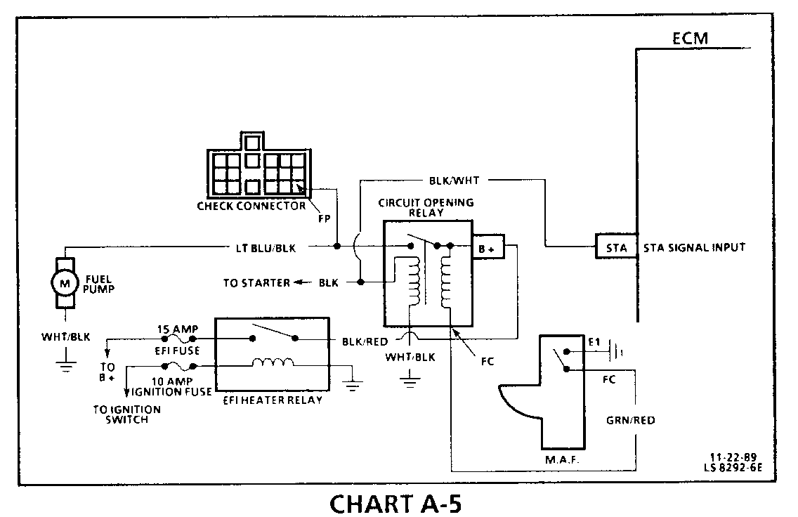
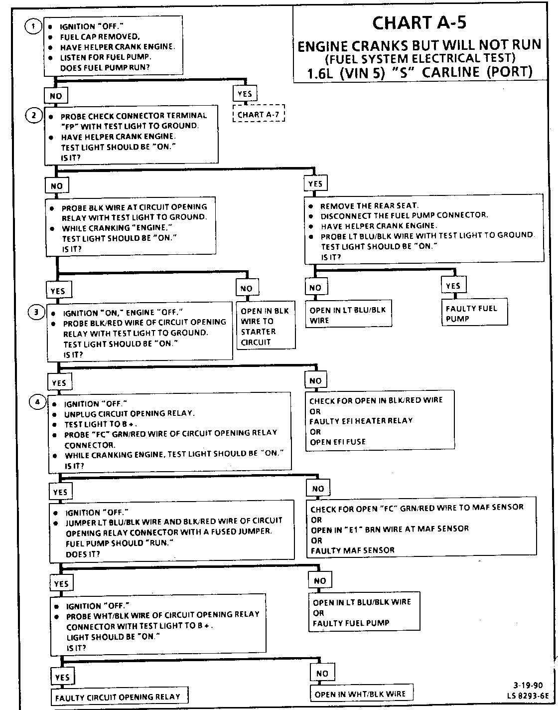
CHART A-5 ENGINE CRANKS BUT WILL NOT RUN (FUEL SYSTEM ELECTRICAL TEST) 1.6L (VIN 5) "S" CARLINE (PORT)
Circuit Description:
When the engine is cranked the signal from starter will turn "ON" the circuit opening relay to operate the fuel pump. Once the engine has started, the starter signal is removed from circuit opening relay and the fuel control switch in MAF sensor continues to run fuel pump. If the fuel control switch in the MAF sensor is nonfunctional, the engine will start but will not stay running.
Test Description: Numbers below refer to circled numbers on the diagnostic chart.
1. Fuel pump should run when ignition is cranked.
2. Test for B+ from circuit opening relay to fuel pump.
3. Checks for B + signal to circuit opening relay.
4. Checks for proper MAF fuel pump switch.
Diagnostic Aids:
Visual inspection of wiring and connectors should be made if an intermittent problem exists.
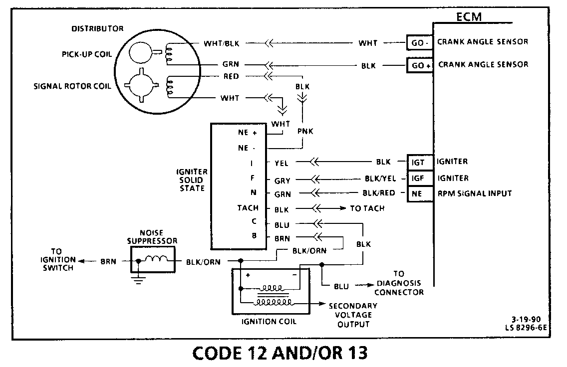
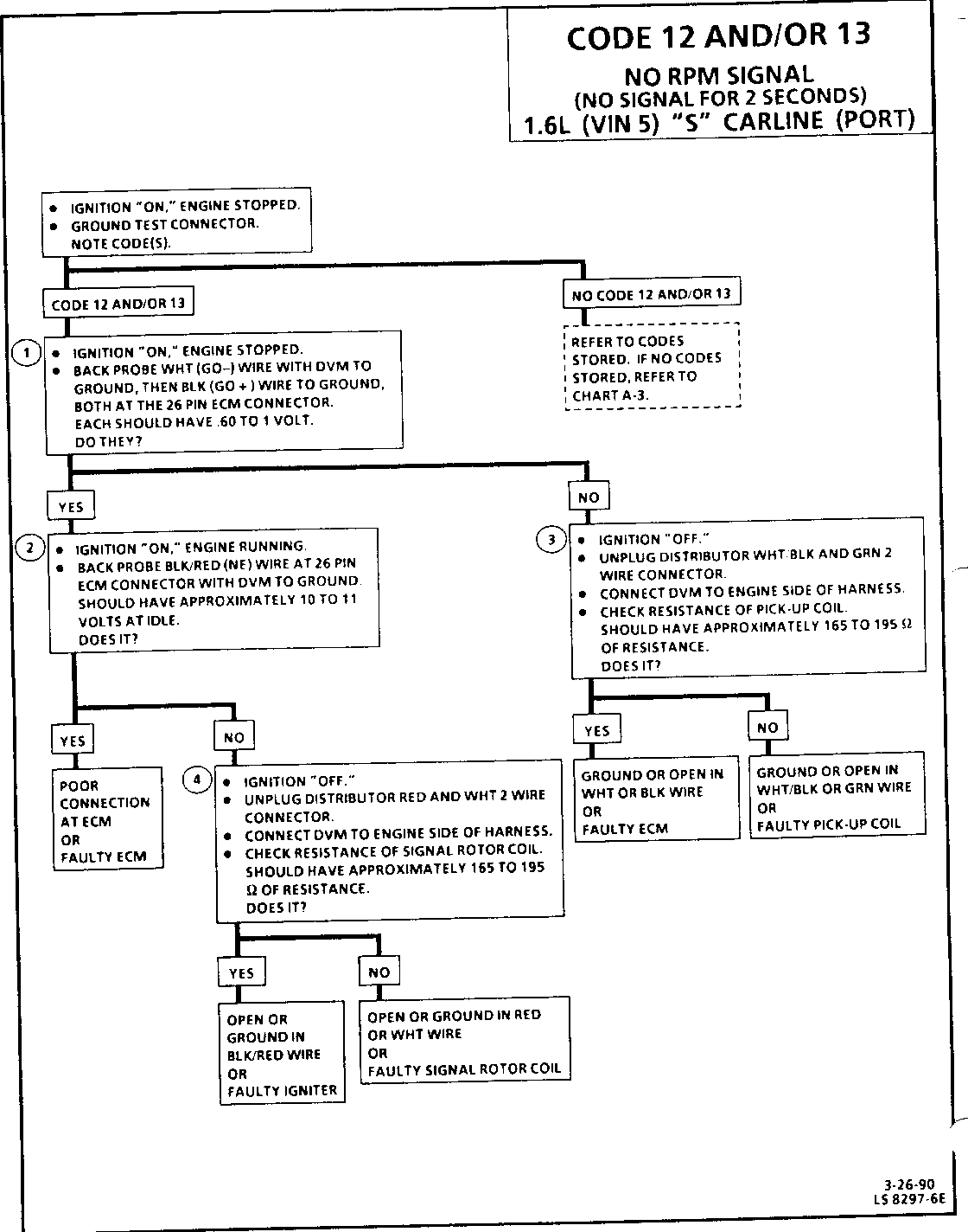
CODE 12 AND/OR 13 NO RPM SIGNAL (NO SIGNAL FOR 2 SECONDS) 1.6L (VIN 5) "S" CARLINE (PORT)
Circuit Description:
The ECM supplies a voltage signal to the pick up coil. As the stator inside the distributor passes the pick up coil the voltage signal is pulled low. This low voltage (signal) is then used to sequence the fuel injector. If this signal is not present for 2 seconds, Code 12 and/or 13 will set.
Test Description: Numbers below refer to circled numbers on the diagnostic chart.
1. Voltage is supplied by the ECM to the pick up coil.
2. Determines if rpm signal is present at the ECM.
3. Checks for proper resistance of the pick up coil.
4. Checks for proper resistance of the signal rotor coil.
Diagnostic Aids:
An intermittent may be caused by a poor connection, rubbed through wire insulation or a wire broken inside the insulation. Inspect ECM harness connectors for backed out terminals, "NE", "GO +", "GO-", "1GT", 1GF", improper mating, broken locks, improperly formed or damaged terminals, poor terminal to wire connection and damaged harness.
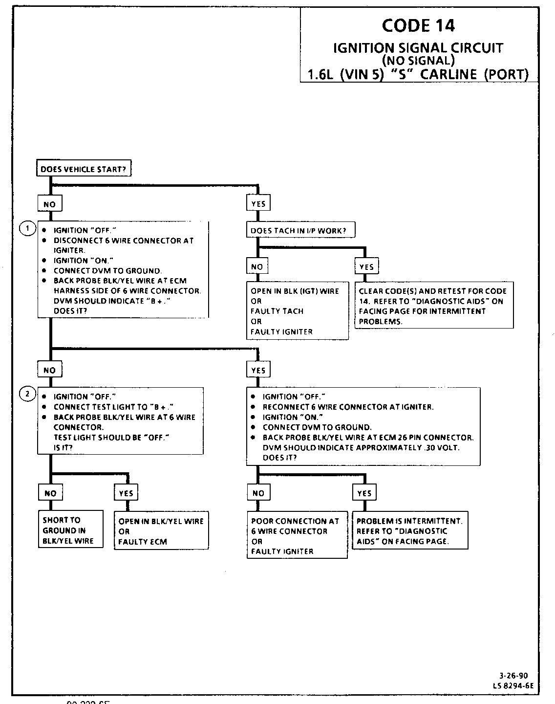
IGNITION SIGNAL CIRCUIT (NO SIGNAL) 1.6L (VIN 5) "'S" CARLINE (PORT)
Circuit Description:
The ECM sends a voltage signal to the igniter on terminal "1GF" of ECM. If this signal is not present four times during cranking, the Code 14 will set. The igniter uses this signal to pulse the injector.
Test Description: Numbers below refer to circled numbers on the diagnostic chart.
1. Verifies B+ signal from ECM.
2. Checks for a short to ground in BLK/YEL wire.
Diagnostic Aids:
An intermittent may be caused by a poor connection rubbed through wire insulation or a wire broken inside the insulation. Inspect ECM and igniter harness connectors for backed out terminals, improper mating, broken locks, improperly formed or damaged terminals, poor terminal to wire connection and damaged harness. Inspect tachometer in I/P for proper operation. If inoperative, check for poor connection, or open or ground in BLK (1GT) wire.

General Motors bulletins are intended for use by professional technicians, not a "do-it-yourselfer". They are written to inform those technicians of conditions that may occur on some vehicles, or to provide information that could assist in the proper service of a vehicle. Properly trained technicians have the equipment, tools, safety instructions and know-how to do a job properly and safely. If a condition is described, do not assume that the bulletin applies to your vehicle, or that your vehicle will have that condition. See a General Motors dealer servicing your brand of General Motors vehicle for information on whether your vehicle may benefit from the information.
