SERVICE MANUAL UPDATE SEC. 6E2 REVISED COMPONENT LOCATION

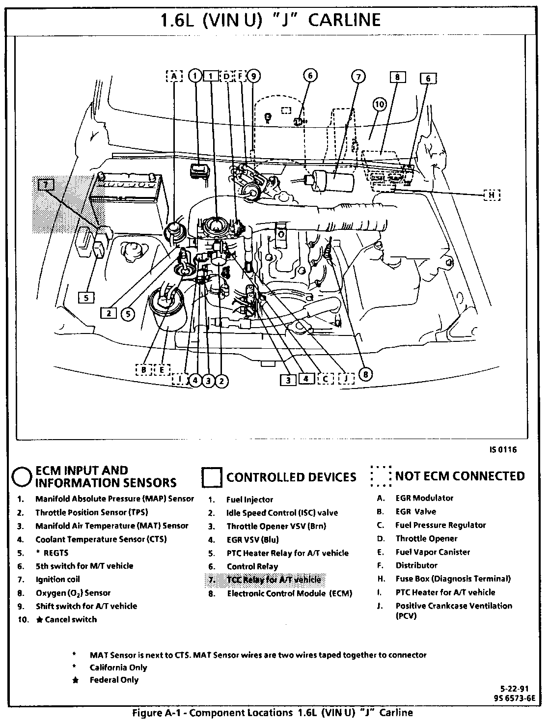
SUBJECT: SERVICE MANUAL UPDATE - SECTION 6E2 - DRIVEABILITY AND EMISSIONS REVISED COMPONENT LOCATION TCC DIAGNOSIS
VEHICLES AFFECTED: 1989-90 "J1" 1.6L (U)
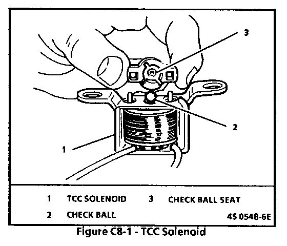
This bulletin has been revised to include the 1989 model year and to include revised pages 6E2-C8-1 and 6E2-C8-4, TCC Diagnosis.
This bulletin serves to revise the 1989 and 1990 Tracker 1.6L (VIN U) "J1" Carline Service Manuals, Section 6E2 "Driveability And Emissions."
The following pages were incorrect:
Page 6E2-A-2, Component Location
Page 6E2-C8-1, TCC Diagnosis
Page 6E2-C8-4, TCC Diagnosis
SECTION C8 TORQUE CONVERTER CLUTCH (TCC) SYSTEM ------------------------------------ CONTENTS -------- GENERAL DESCRIPTION C8-1 DIAGNOSIS C8-1 PURPOSE C8-1 ON-VEHICLE SERVICE C8-1 OPERATION C8-1 PARTS INFORMATION C8-1 CIRCUIT DESCRIPTION C8-1
GENERAL DESCRIPTION
PURPOSE
The Torque Converter Clutch (TCC) system is designed to eliminate power loss by the converter (slippage) to increasing fuel economy. By locking h converter clutch, a more effective coupling to flywheel is achieved. The converter clutch operated by an ECM controlled solenoid.
OPERATION
Engagement of the TCC is accomplished by a solenoid operated valve within the transmission. The solenoid is activated when an internal switch in the ECM is grounded. Although the ECM may command the TCC "ON," the converter clutch will not apply until internal transmission fluid pressure requirements are met. See AUTOMATIC TRANSMISSION (SECTION 7A).
Before the ECM activates the TCC solenoid, several inputs must be monitored.
o Coolant Temperature - The engine coolant temperature must be above a certain value before the TCC can be applied.
o Throttle Position Sensor (TPS) - After the TCC is applied, during low engine load condition, the ECM uses the information from the TPS to release the clutch when the car is accelerating or decelerating at a certain rate.
CIRCUIT DESCRIPTION
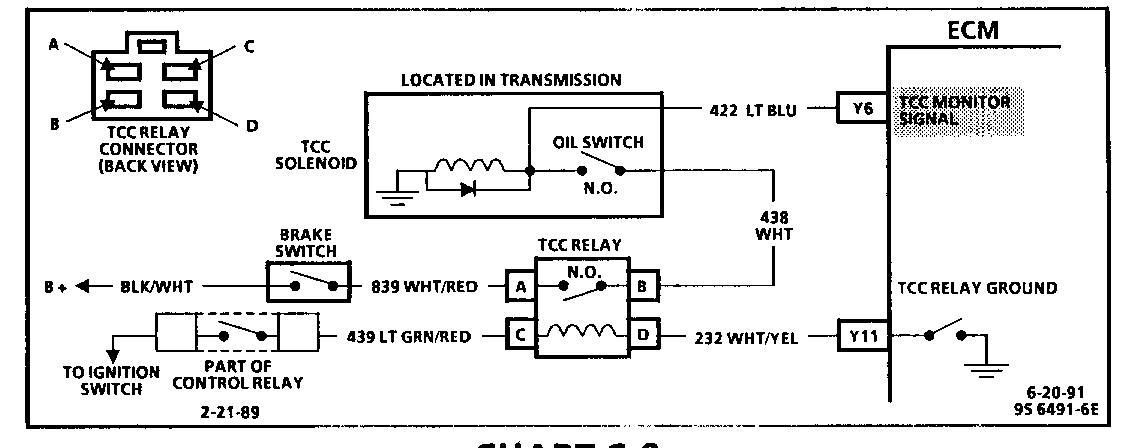
The 12 volt power supply for the solenoid in the transmission is provided through a normally closed switch located on the brake pedal linkage. When the brake pedal is depressed (switch open) the power supply to the TCC solenoid is interrupted and the TCC is disengaged regardless of any other conditions. A 3rd gear switch (closed in 3rd gear) is placed in series between the brake switch and the TCC solenoid. This switch will prevent TCC engagement until the transmission is in 3rd gear.
When the brake pedal is not depressed (switch closed) and the transmission is in 3rd gear (3rd gear switch closed), battery voltage will be fed to the TCC solenoid. If the ECM has determined that conditions are correct, the circuit from the TCC solenoid will be completed to ground through the ECM and the TCC solenoid will be activated.
DIAGNOSIS
The diagnosis of the TCC system is covered in CHART C-8A.
If the ECM doesn't switch the TCC "ON" during driving, but the TCC will turn "ON" when the "test" terminal is grounded with ignition "ON" and engine "OFF," sensors such as coolant, speed, and throttle position should be checked.
ON-VEHICLE SERVICE
See AUTOMATIC TRANSMISSION (SECTION 7A) for TCC solenoid service information.
PARTS INFORMATION
PART NAME GROUP Solenoid, TCC 4.122
CHART C-8 TORQUE CONVERTER CLUTCH (TCC) LOCK-UP RELAY SYSTEM CHECK 1.6L (VIN U) "J" CARLINE (TBI) ------------------------------
Circuit Description:
Based on signals from the TPS (throttle opening), the ignition coil, and CTS the ECM will provide the ground for the Torque Converter Clutch (TCC) circuit. The TCC (lock up) solenoid, under control of the brake pedal switch, automatic transmission oil pressure switch, and the TCC relay, opens and closes the automatic transmission oil passage to lock and unlock the torque converter clutch. For further description of operation of TCC, see Section "7A".
Test Description: most of the tests in this chart are checking for opens or shorts to ground or voltage. Shorts to voltage are unlikely and the most common problems are loose connectors and dirty terminal contacts.
1. This test attempts to eliminate the ECM TCC ground at Y11. If the light is turned on then the ECM is grounding the circuit properly. If not then the ECM is at fault and the ECM should be replaced after doing the ECM circuit resistance check in Section "C1".
Diagnostic Aids: TCC will operate only under the following conditions:
1. Throttle valve opening is greater than 7 degrees and less than 62 degrees.
2. Coolant temperature is greater than 60C (140F).
3. Brake pedal released (brake pedal switch "ON").
4. Automatic transmission oil pressure is normal (oil pressure switch "ON").


General Motors bulletins are intended for use by professional technicians, not a "do-it-yourselfer". They are written to inform those technicians of conditions that may occur on some vehicles, or to provide information that could assist in the proper service of a vehicle. Properly trained technicians have the equipment, tools, safety instructions and know-how to do a job properly and safely. If a condition is described, do not assume that the bulletin applies to your vehicle, or that your vehicle will have that condition. See a General Motors dealer servicing your brand of General Motors vehicle for information on whether your vehicle may benefit from the information.
