Removal Procedure
- Disable the SIR system. Refer to SIR Disabling and Enabling .
- Disconnect the negative battery cable. Refer to Battery Negative Cable Disconnection and Connection .
- Remove the engine assembly. Refer to Engine Replacement for the 3.6L Engine or Engine Replacement for the 6.0L Engine.
- Remove the ABS unit. Refer to Brake Pressure Modulator Valve Assembly Replacement .
- Remove the brake master cylinder. Refer to Master Cylinder Replacement .
- Remove the vacuum brake booster. Refer to Power Vacuum Brake Booster Replacement .
- Remove the engine control module. Refer to Engine Control Module Replacement for the 3.6L Engine or Engine Control Module Replacement for the 6.0L Engine.
- Remove the underhood electrical centre. Refer to Underhood Electrical Center or Junction Block Replacement .
- Remove the negative battery cable from the engine bay. Refer to Battery Negative Cable Replacement .
- Remove the positive battery cable from the engine bay. Refer to Battery Positive Cable Replacement .
- Raise and support the vehicle. Refer to Lifting and Jacking the Vehicle .
- Remove the air inlet grille. Refer to Air Inlet Grille Panel Replacement .
- Remove the front wheelhouse liner. Refer to Front Wheelhouse Liner Replacement .
- Remove the coolant reservoir. Refer to Coolant Recovery Reservoir Replacement .
- Remove the front bumper fascia. Refer to Front Bumper Fascia Replacement .
- Remove the front end module. Refer to Front End Panel Module Carrier Assembly Replacement .
- Remove the front fender assembly. Refer to Front Fender Replacement .
- Remove the front wheel hub assembly. Refer to Front Wheel Bearing and Hub Replacement .
- Remove the front strut assembly. Refer to Strut Assembly Replacement .
- Remove the cargo liner. Refer to Cargo Box Liner Replacement .
- Remove the rear wheelhouse liner. Refer to Rear Wheelhouse Panel Liner Replacement .
- Remove the rear frame assembly. Refer to Rear Frame Replacement .
- Remove the filler tube. Refer to Filler Tube Replacement .
- Remove the fuel filler door. Refer to Fuel Tank Filler Door Replacement .
- Remove the fuel filler door release actuator. Refer to Fuel Tank Filler Door Lock Actuator Replacement .
- Remove the fuel lines. Refer to Fuel Hose/Pipes Replacement - Chassis for the 3.6L Engine or Fuel Hose/Pipes Replacement - Chassis for the 6.0L Engine.
- Remove the fuel tank. Refer to Fuel Tank Replacement .
- Remove the brake lines. Refer to Brake Pipe Replacement .
- Remove the rear bumper fascia. Refer to Rear Bumper Fascia Replacement .
- Remove the plenum chamber. Refer to Air Inlet Assembly Replacement .
- Remove the front doors. Refer to Front Side Door Replacement .
- Remove the front seats. Refer to Front Seat Replacement - Bucket .
- Remove the front seat belts. Refer to Front Seat Belt Replacement .
- Remove the instrument panel carrier. Refer to Instrument Panel Carrier Replacement .
- Remove the HVAC module assembly. Refer to HVAC Module Assembly Replacement .
- Remove the headliner. Refer to Headlining Trim Panel Replacement .
- Remove the remote function actuator. Refer to Remote Control Door Lock Receiver and Theft Deterrent Module Replacement .
- Remove the positive battery cable from the vehicle. Refer to Battery Positive Cable Replacement .
- Remove the roof outer panel. Refer to Roof Outer Replacement .
- Remove the roof weld joint reveal moulding. Refer to Roof Weld Joint Reveal Molding Replacement .
- Remove the rocker panel moulding. Refer to Rocker Panel Molding Replacement .
- Remove the windshield pillar garnish moulding. Refer to Windshield Pillar Garnish Molding Replacement .
- Remove the rear header trim. Refer to Roof Rear Header Panel Replacement .
- Remove the body side roof drip moulding. Refer to Body Side Roof Drip Molding Replacement .
- Remove the body lock pillar trim. Refer to Body Lock Pillar Applique Replacement .
- Remove the endgate. Refer to Endgate Replacement .
- Note the location and remove the sealers and anti-corrosion materials from the repair area, as necessary. Refer to Anti-Corrosion Treatment and Repair .
- Remove the body side panel to upper dash panel body sealer (1).
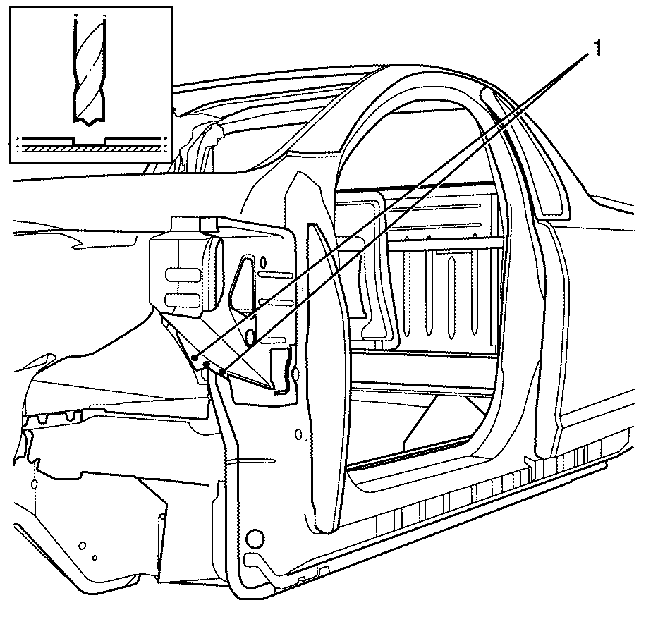
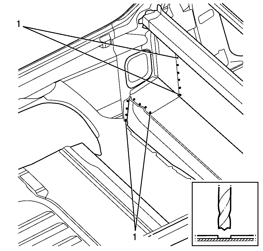
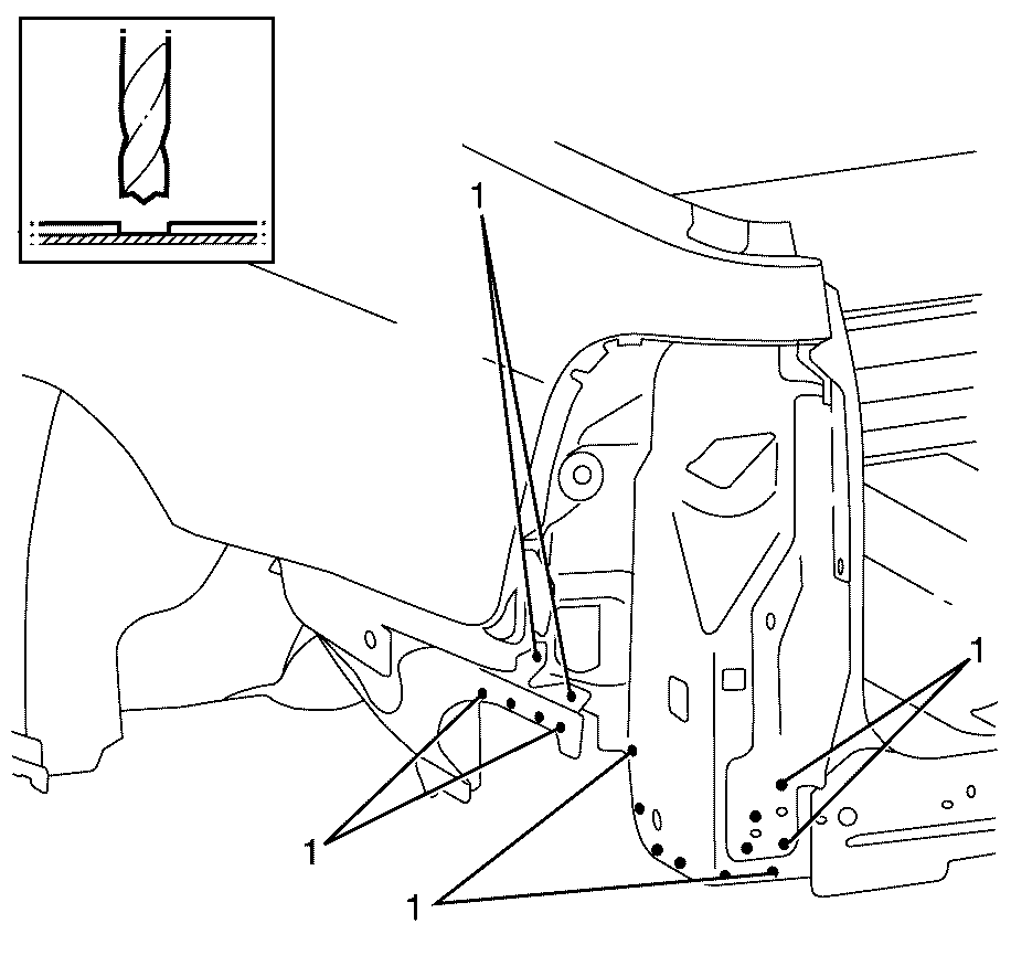
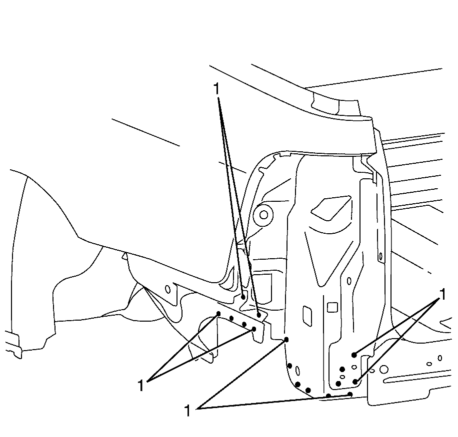
- Locate, mark and drill out the factory welds attaching the upper wheelhouse brace to the front wheelhouse assembly (1).
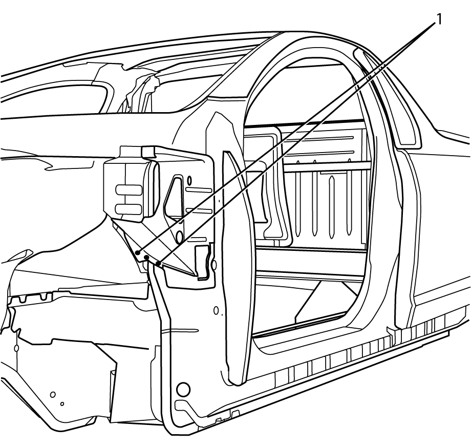
- Locate, mark and drill out the factory welds attaching the upper wheelhouse brace to the front hinge pillar (1).
- Locate, mark and remove the factory seam welds attaching the body side panel assembly to the front hinge pillar (1).
- Remove the upper wheelhouse brace from the front wheelhouse assembly.
- Locate, mark and drill out the factory welds attaching the upper wheelhouse brace to the front hinge pillar (1).
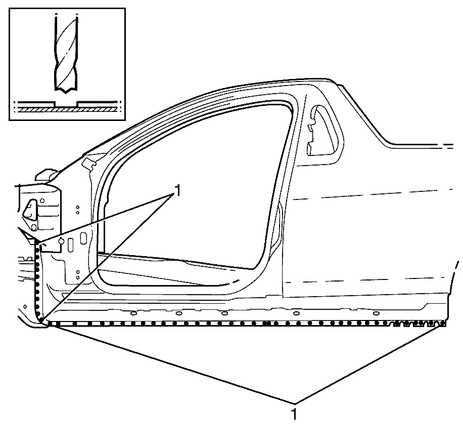
- Locate, mark and drill out the factory welds attaching the body side panel assembly to the front hinge pillar (1).
- Locate, mark and drill out the factory welds attaching the body side panel assembly to the vehicle (1).
- Locate, mark and remove the factory welds attaching the body side panel assembly to the vehicle (1).
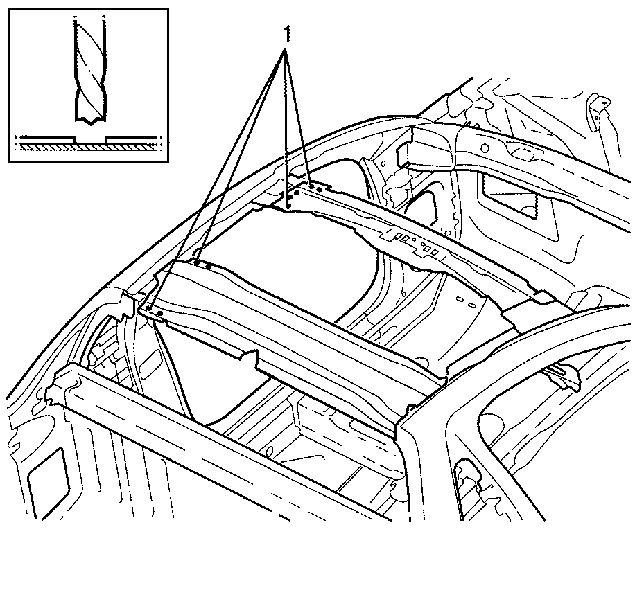
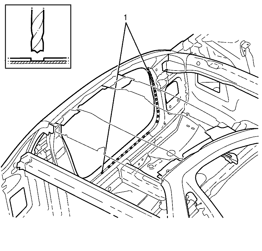
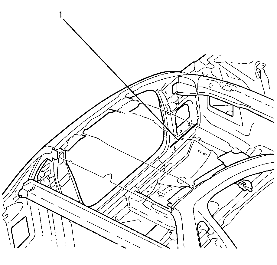
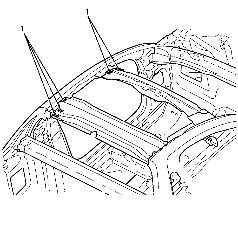
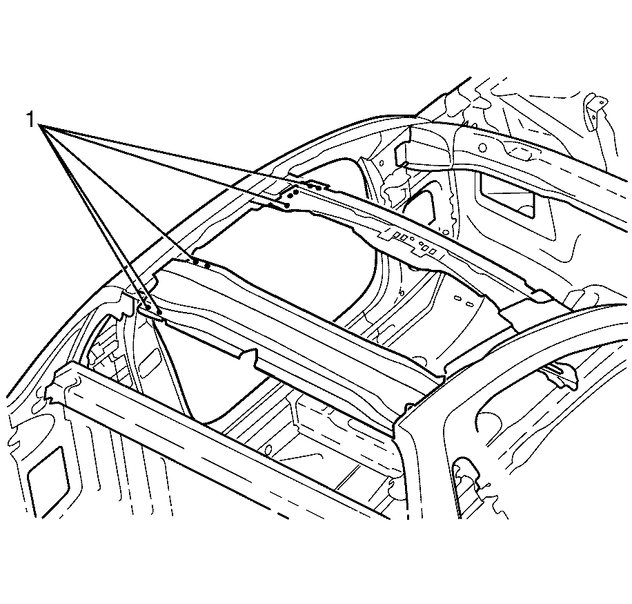
- Locate, mark and drill out the factory welds attaching the body side panel assembly to both roof header panels (1).
- Remove the rear window panel drain tube (1) from the rear window panel reinforcement.
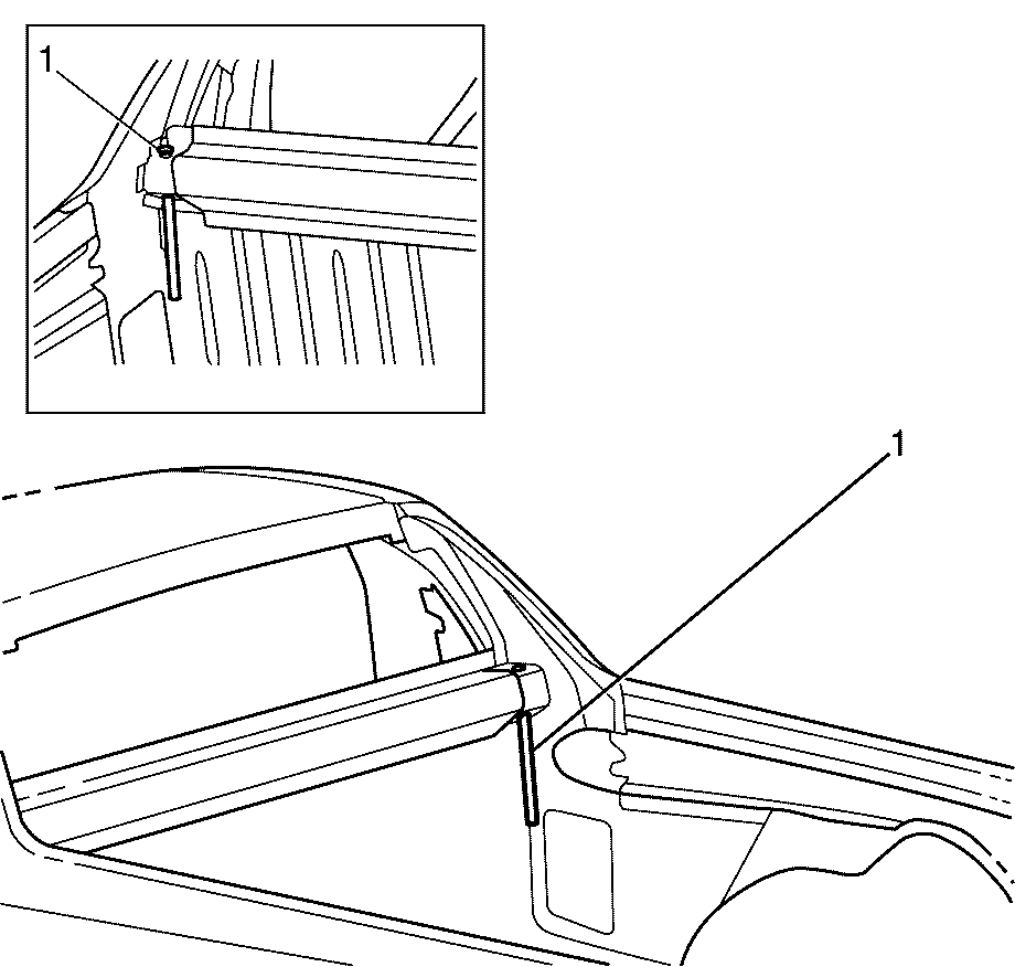
- Remove the rear body side panel support brace (1) from the body side.
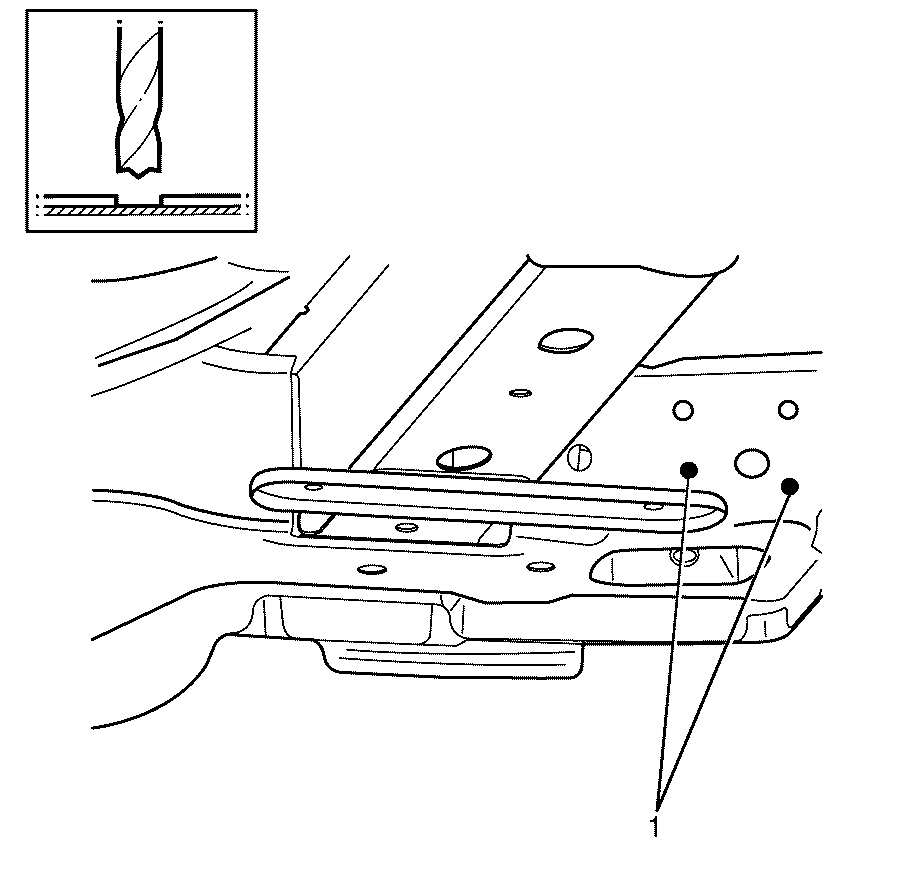
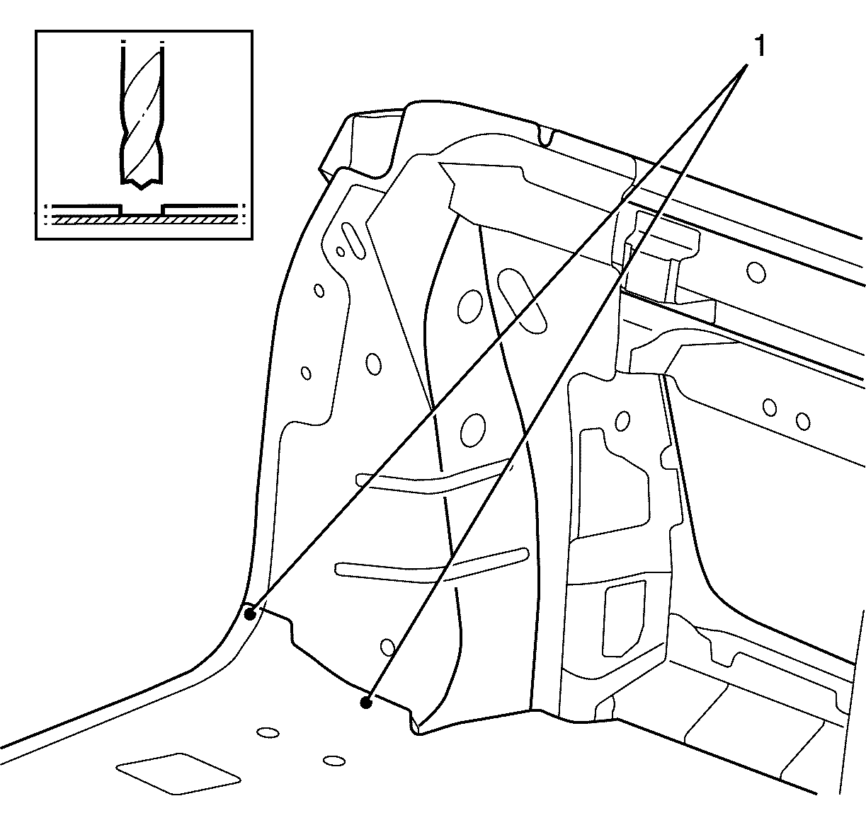
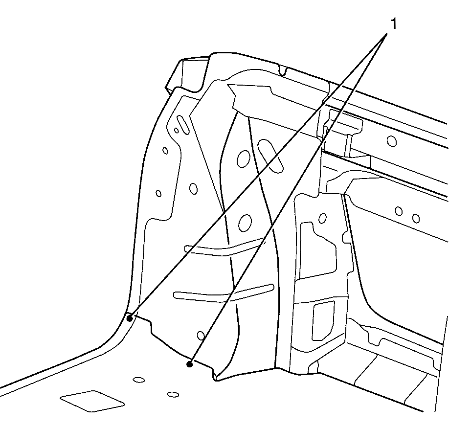
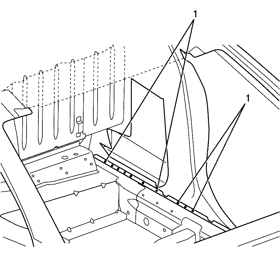
- Locate, mark and drill out the factory welds attaching the body side panel assembly to the seat back panel assembly and the underbody assembly (1).
- Locate, mark and remove the structural adhesive (1) attaching the body side panel assembly to the inner guard assembly.
- Locate, mark and drill out the factory welds attaching the body side panel assembly to the vehicle (1).
- Locate, mark and drill out the factory welds attaching the body side panel assembly to the vehicle (1).
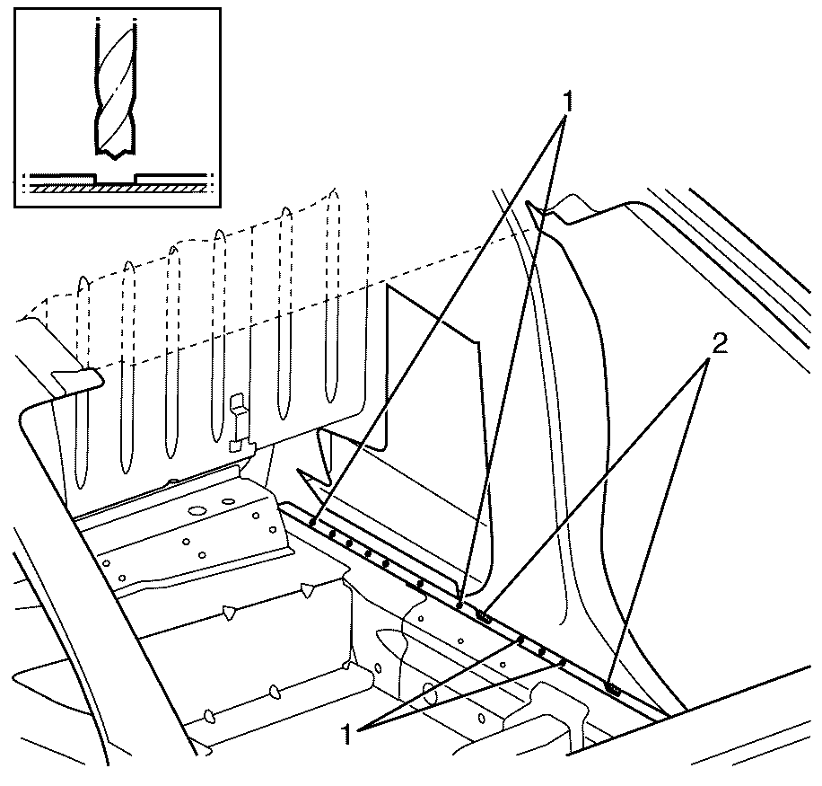
- Locate, mark and drill out the factory welds attaching the body side panel assembly to the body side (1). Locate, mark and remove the factory welds attaching the body side panel assembly to the body side (2).
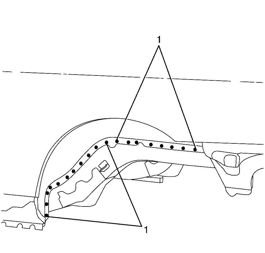
- Locate, mark and drill out the factory welds attaching the body side panel assembly to the inner rear wheelhouse (1).
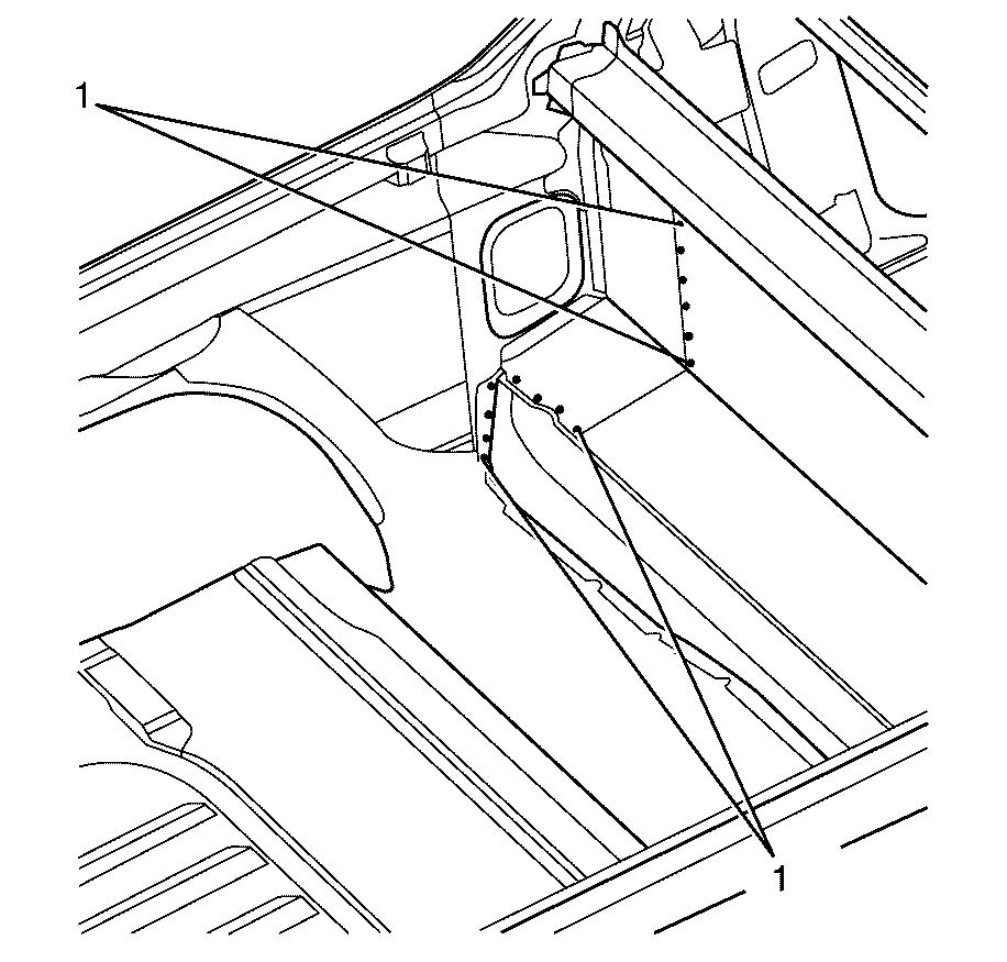
- Locate, mark and drill out the factory welds attaching the body side panel assembly to the rear end panel (1).
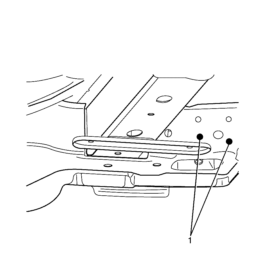
- Locate, mark and drill out the factory welds attaching the body side panel assembly to the rear crossmember (1).
- Locate, mark and drill out the factory welds attaching the body side panel assembly to the rear floor panel (1).
- Remove the body side panel from the vehicle.
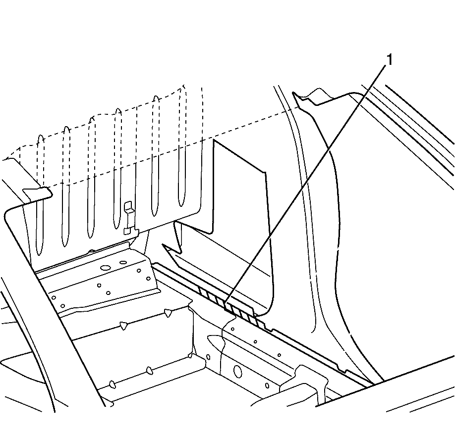
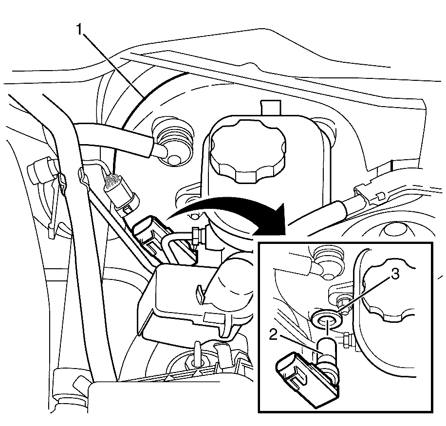
- Remove the sealer (1) from the front plenum panel.
- Remove the seam sealer (2) from the body side.
Caution: Refer to Approved Equipment for Collision Repair Caution in the Preface section.
Caution: Refer to Safety Glasses Caution in the Preface section.
Caution: Refer to Foam Sound Deadeners Caution in the Preface section.
Caution: Refer to Battery Disconnect Caution in the Preface section.







Important: Clean all adhesive mating surfaces in accordance with the adhesive manufacturer's specifications.
Installation Procedure
- Drill 8 mm (5/16 in) plug weld holes as necessary in the locations noted when disassembling.
- Clean and prepare the mating surfaces of both parts of the body side panel assembly.
- Install the un-expanded noise baffle (1) to the body side panel assembly.
- Apply an approved structural adhesive to the top edge of the inner hinge pillar (1).
- Apply an approved structural adhesive to the body side (1).
- Apply an approved structural adhesive to the seat back panel assembly and the underbody assembly (1).
- Apply the primary sealer along the lower hinge pillar (1).
- Apply an approved structural adhesive to the inner wheelhouse (1).
- Align the body side panel assembly centre pillar to the indented flange on the inner rocker panel (1).
- Align the body side panel hinge pillar (1) to the inner lower hinge pillar (2).
- Weld the body side panel assembly to the front hinge pillar (1).
- Seam weld the inner lower hinge pillar to inner upper hinge pillar (1) 60 mm (2.36 in) using a metal inert gas (MIG) welder.
- Apply an approved structural adhesive to the bottom edge of roof header panels (1).
- Weld the body side panel assembly to both roof header panels (1).
- Weld the body side panel assembly to the front hinge pillar (1).
- Weld the body side panel assembly to the rear floor panel (1).
- Weld the body side panel assembly to the rear crossmember (1).
- Weld the body side panel assembly to the rear end panel (1).
- Weld the body side panel assembly to the inner rear wheelhouse (1).
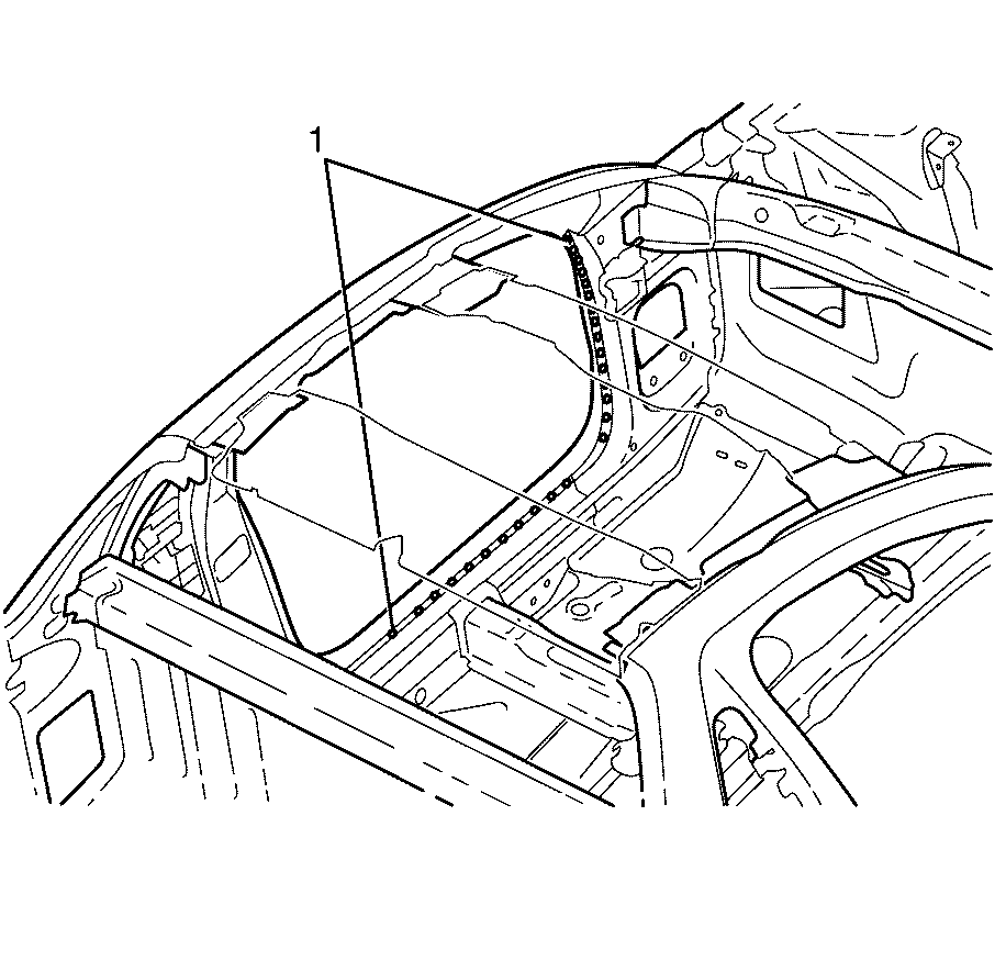
- Puddle weld the body side panel assembly to the body side (1).
- Weld the body side panel assembly to the body side (1).
- Weld the body side panel assembly to the body side (1).
- Weld the body side panel assembly to the body side (1).
- Weld the body side panel assembly to the seat back panel assembly and the underbody assembly (1).
- Weld the body side panel assembly to the seat back panel assembly and the underbody assembly (1).
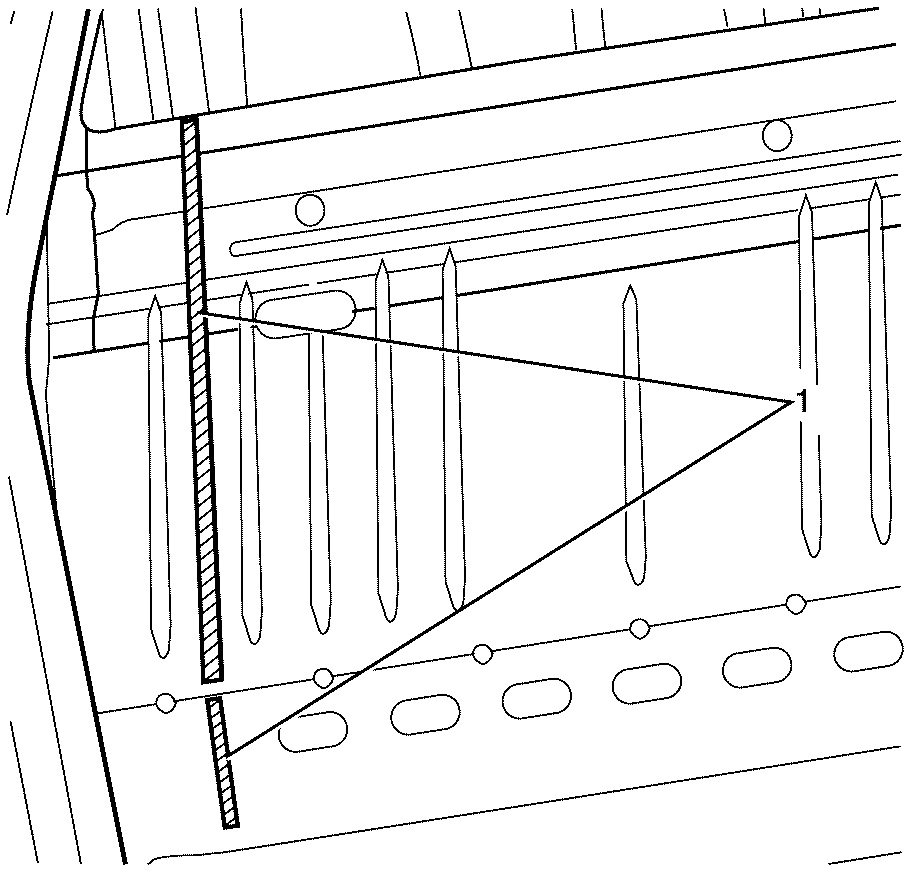
- Apply the primary sealer along the rear edge of the upper wheelhouse brace (1) .
- Weld the upper wheelhouse brace to the front hinge pillar (1).
- Weld the upper wheelhouse brace to the front hinge pillar (1).
- Weld the upper wheelhouse brace to the front wheelhouse assembly (1).
- Apply the secondary sealer (1) to the front plenum panel.
- Apply the secondary sealer (2) to the lower hinge pillar.
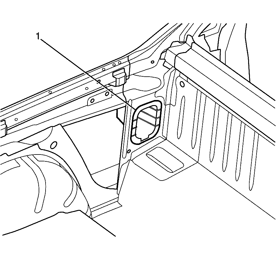
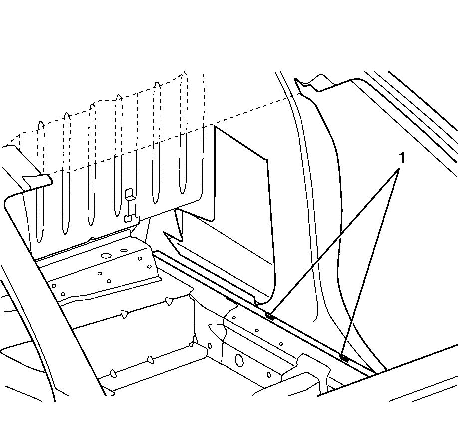
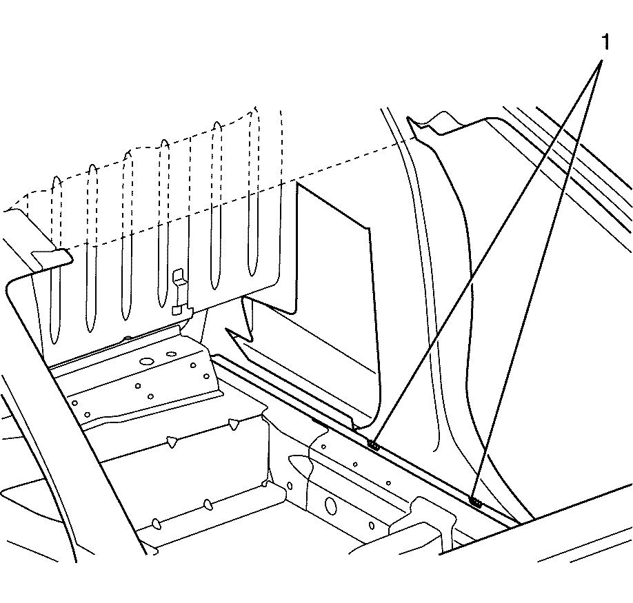
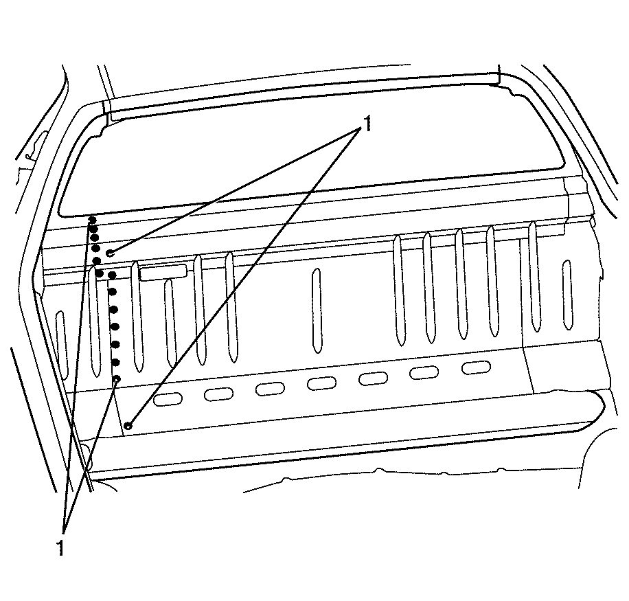
- Apply an approved expanding foam sealer through the two access holes (1) in the rear wheelhouse assembly.
- Install the rear window panel drain tube (1) to the rear window panel reinforcement.
- Install the rear body side panel support brace (1) to the body side.
- Paint the repaired area. Refer to Basecoat/Clearcoat Paint Systems .
- Install the endgate. Refer to Endgate Replacement .
- Install the body lock pillar trim. Refer to Body Lock Pillar Applique Replacement .
- Install the body side roof drip moulding. Refer to Body Side Roof Drip Molding Replacement .
- Install the rear header trim. Refer to Roof Rear Header Panel Replacement .
- Install the windshield pillar garnish moulding. Refer to Windshield Pillar Garnish Molding Replacement .
- Install the rocker panel moulding. Refer to Rocker Panel Molding Replacement .
- Install the roof weld joint reveal moulding. Refer to Roof Weld Joint Reveal Molding Replacement .
- Install the roof outer panel. Refer to Roof Outer Replacement .
- Install the positive cable to the vehicle. Refer to Battery Positive Cable Replacement .
- Install the remote function actuator. Refer to Remote Control Door Lock Receiver and Theft Deterrent Module Replacement .
- Install the headliner. Refer to Headlining Trim Panel Replacement .
- Install the HVAC. Refer to HVAC Module Assembly Replacement .
- Install the instrument panel carrier. Refer to Instrument Panel Carrier Replacement .
- Install the front seat belts. Refer to Front Seat Belt Replacement .
- Install the front seats. Refer to Front Seat Replacement - Bucket .
- Install the front doors. Refer to Front Side Door Replacement .
- Install the plenum chamber. Refer to Air Inlet Assembly Replacement .
- Install the rear bumper fascia. Refer to Rear Bumper Fascia Replacement .
- Install the brake lines. Refer to Brake Pipe Replacement .
- Install the fuel tank. Refer to Fuel Tank Replacement for the 3.6L Engine or Fuel Filter Replacement for the 6.0L engine.
- Install the fuel lines. Refer to Fuel Hose/Pipes Replacement - Chassis for the 3.6L Engine or Fuel Hose/Pipes Replacement - Chassis for the 6.0L engine.
- Install the fuel filler door release actuator. Refer to Fuel Tank Filler Door Lock Actuator Replacement .
- Install the fuel filler door. Refer to Fuel Tank Filler Door Replacement .
- Install the filler tube. Refer to Filler Tube Replacement .
- Install the rear frame assembly. Refer to Rear Frame Replacement .
- Install the rear wheelhouse liner. Refer to Rear Wheelhouse Panel Liner Replacement .
- Install the cargo liner. Refer to Cargo Box Liner Replacement .
- Install the front strut assembly. Refer to Strut Assembly Replacement .
- Install the front wheel hub assembly. Refer to Front Wheel Bearing and Hub Replacement .
- Install the front fender assembly. Refer to Front Fender Replacement .
- Install the front end module. Refer to Front End Panel Module Carrier Assembly Replacement .
- Install the front bumper fascia. Refer to Front Bumper Fascia Replacement .
- Install the coolant reservoir. Refer to Coolant Recovery Reservoir Replacement .
- Install the front wheelhouse liner. Refer to Front Wheelhouse Liner Replacement .
- Install the air inlet grille. Refer to Air Inlet Grille Panel Replacement .
- Install the positive battery cable to the engine bay. Refer to Battery Positive Cable Replacement .
- Install the negative battery cable to the engine bay. Refer to Battery Negative Cable Replacement .
- Install the underhood electrical centre. Refer to Underhood Electrical Center or Junction Block Replacement .
- Install the engine control module. Refer to Engine Control Module Replacement for the 3.6L engine or Engine Control Module Replacement for the 6.0L engine.
- Install the vacuum brake booster. Refer to Power Vacuum Brake Booster Replacement .
- Install the brake master cylinder. Refer to Master Cylinder Replacement .
- Install the ABS unit. Refer to Brake Pressure Modulator Valve Assembly Replacement .
- Install the engine assembly. Refer to Engine Replacement for the 3.6L engine or Engine Replacement for the 6.0L engine.
- Connect the negative battery cable. Refer to Battery Negative Cable Disconnection and Connection .
- Enable the SIR system. Refer to SIR Disabling and Enabling .
- If re-programming is required. Refer to Control Module References .
Important: Spot welding is the preferred method for attaching panels and should be used whenever possible. A plug weld should only be performed where spot welding is not possible.
Important: If the location of the original plug weld holes cannot be determined, or if structural weld-thru adhesive is present, space the plug weld holes every 32 mm (1¼ in).
Important: Follow the adhesive manufacturer's instructions during the assembly process. Heat must be applied as per the manufacturer's specifications to cure the adhesives and to expand the sealing baffles.
Important: Secondary sealer must be applied to the perimeter of all flanges. Secondary sealer must be applied to all welds/joints that were originally covered by secondary sealer.









Important: All joints and welds must be checked for water leaks before the vehicle is fully reassembled.
