Strut Assembly Replacement HSV Except Clubsport
Tools Required
E7115 Angle Wrench.
Removal Procedure - Type B
- Raise and support the vehicle. Refer to Lifting and Jacking the Vehicle .
- Remove the front wheel. Refer to Tire and Wheel Removal and Installation .
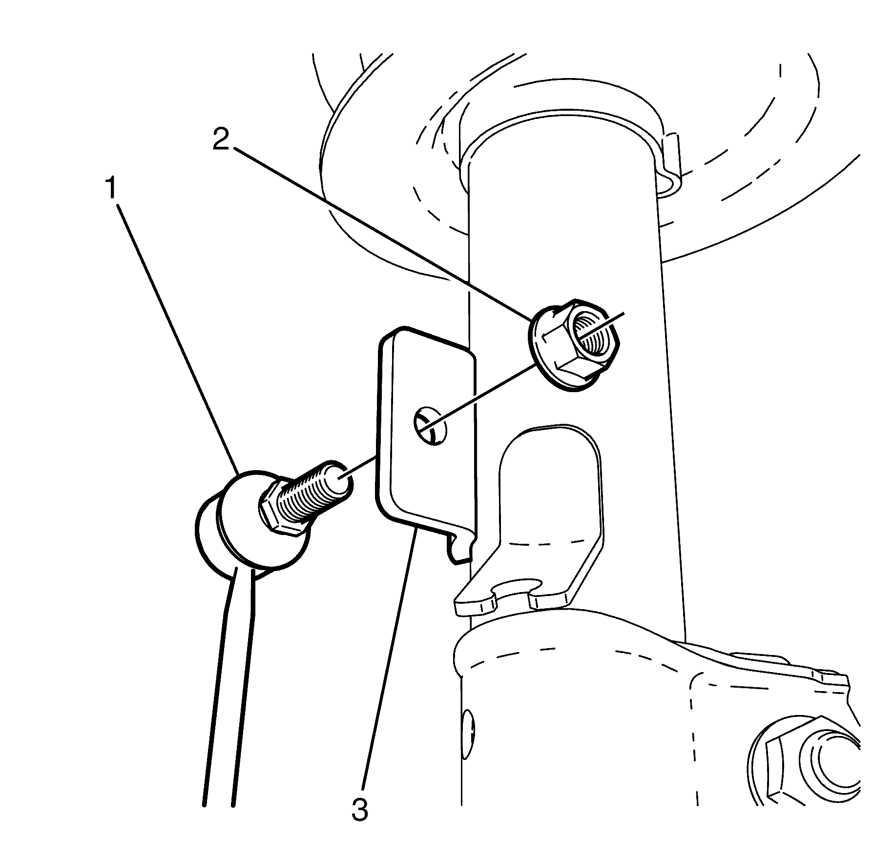
- Remove the stabiliser bar link to strut assembly bracket retaining nut (2).
- Disconnect the stabiliser bar link (1) from the strut assembly bracket (3).
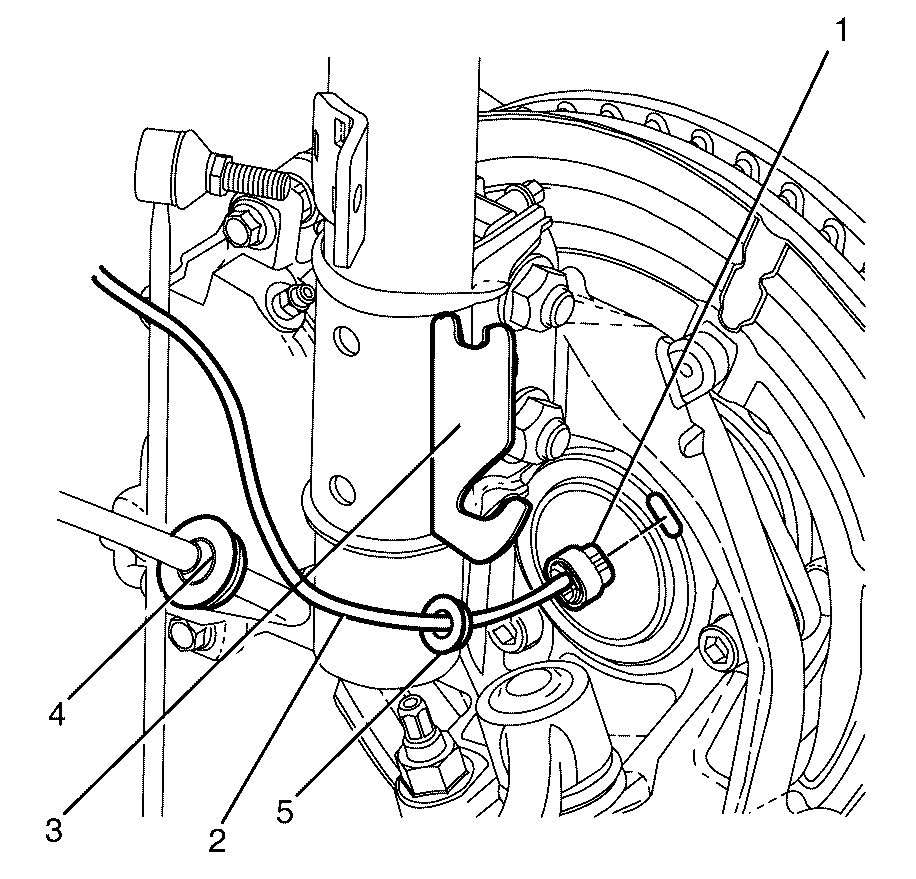
- Disconnect the wheel speed sensor electrical connector (1).
- Disconnect the wheel speed sensor harness connector (2) from the strut assembly bracket (3).
- Disconnect the brake hose (4) from the strut assembly bracket (3).
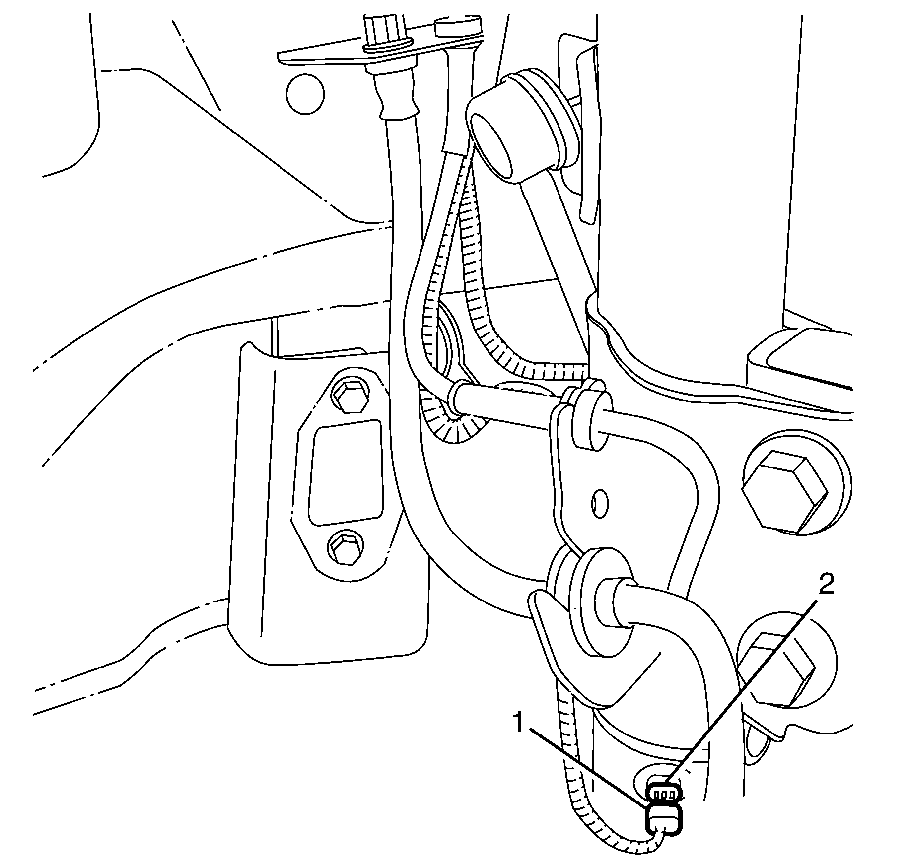
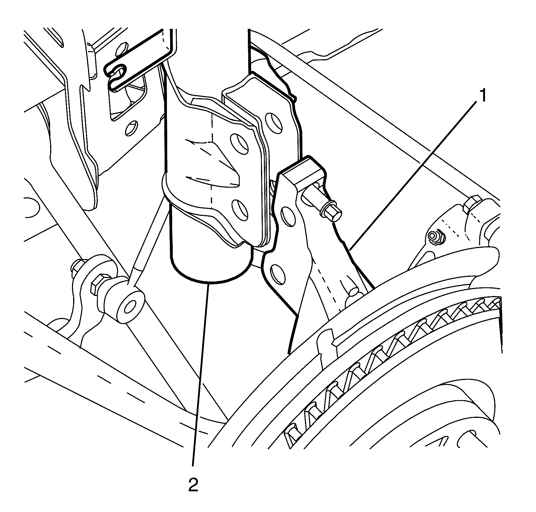
- Disconnect the ESC harness connector (1) from the strut assembly (2).
- Remove the steering knuckle to strut assembly retaining bolts (3), nuts (1) and washers (2).
- Disconnect the steering knuckle (1) from the strut assembly (2).
- Lower the vehicle.
- Remove the stud dust cover (1) from the strut assembly to body retaining nut (2).
- Remove the strut assembly to body retaining nut (2) while holding the strut piston shaft (4).
- Remove the strut assembly to body retaining plate (3).
- Remove the strut assembly from the vehicle.
- Inspect all parts for wear and damage, replace any damaged or worn components.
Caution: Refer to Safety Glasses Caution in the Preface section.
Caution: Refer to Vehicle Lifting Caution in the Preface section.
Important: Nuts with micro-encapsulated thread sealant must be discarded after removal.
Discard the nut.
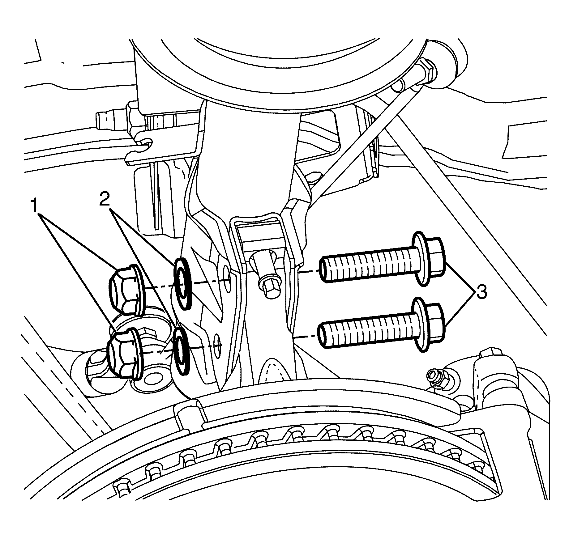
Important: The steering knuckle to strut assembly retaining bolts (3), nuts (1) and washers (2) are single use parts. They must be discarded after removal.
Discard the bolts, nuts and washers.
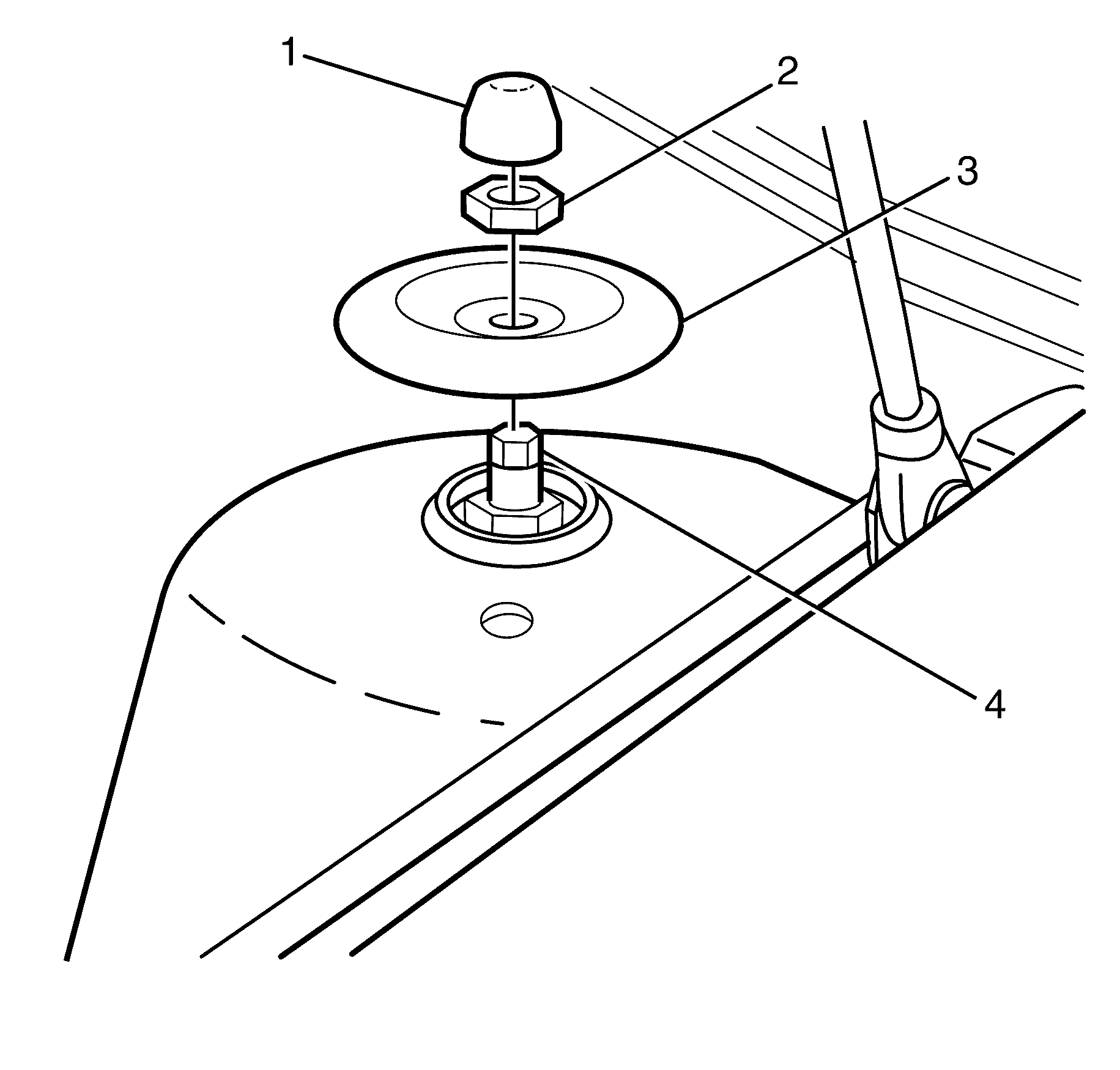
Important: The strut assembly (4) must be supported from underneath before the strut assembly to body retaining nut (2) is removed.
Discard the nut.
Installation Procedure - Type B
- Check the torque of the strut assembly retaining nut (1), correct if necessary.
- Install the strut assembly (3) to the vehicle (4).
- Install strut assembly to body retaining plate (1).
- Install the NEW strut assembly to body retaining nut (2) to the strut assembly (3).
- Raise the vehicle.
- Install the steering knuckle (1) to the strut assembly (2).
- Install the NEW steering knuckle to strut assembly retaining bolts (3), nuts (1) and washers (2).
- Lower the vehicle.
- Tighten the NEW strut assembly to body retaining nut (2).
- Install the stud dust cover (1) to the strut assembly to body retaining nut (2).
- Raise the vehicle.
- Install the brake hose (4) to the strut assembly bracket (3).
- Connect the wheel speed sensor harness connector (1).
- Connect the wheel speed sensor connector (2) to the strut assembly bracket (3).
- Connect the ESC harness connector (1) to the strut assembly (2).
- Connect the stabiliser bar link (1) to the strut assembly bracket (3).
- Install the stabiliser bar link to strut assembly bracket retaining nut (2).
- Install the front wheel. Refer to Tire and Wheel Removal and Installation
- Remove the safety stands.
- Lower the vehicle to the ground.
- Bounce the vehicle several times to settle the suspension.
- Check and adjust the wheel alignment. Refer to Wheel Alignment Measurement in Wheel Alignment.
- Tighten the strut assembly to steering knuckle retaining bolts (2) and nuts (1).
Notice: Refer to Fastener Notice in the Preface section.
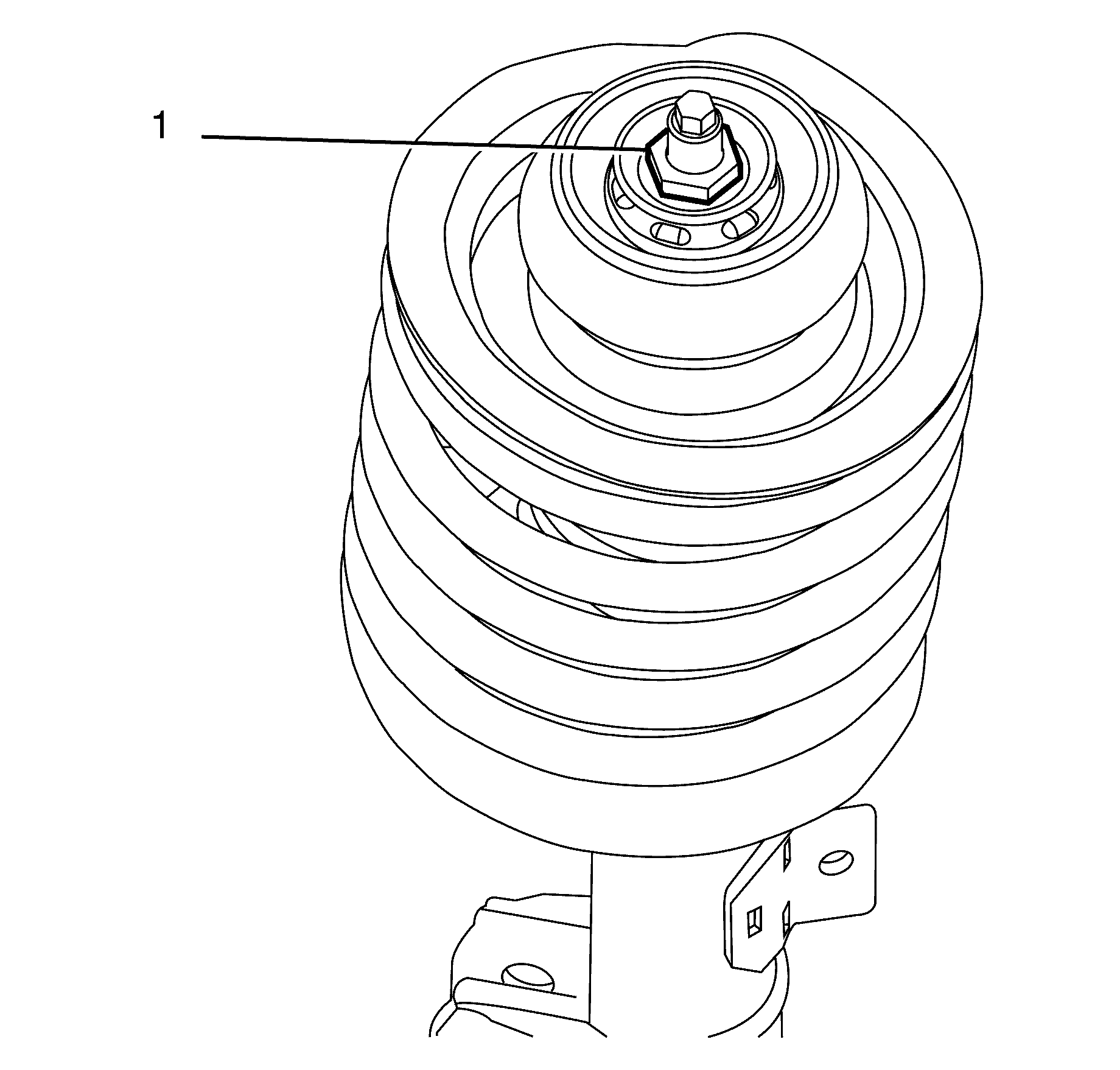
Important: The strut assembly retaining nut (1) must be checked for correct torque before installing the strut assembly into the vehicle. The strut assembly retaining nut torque must be 75 Nm (55 lb ft).
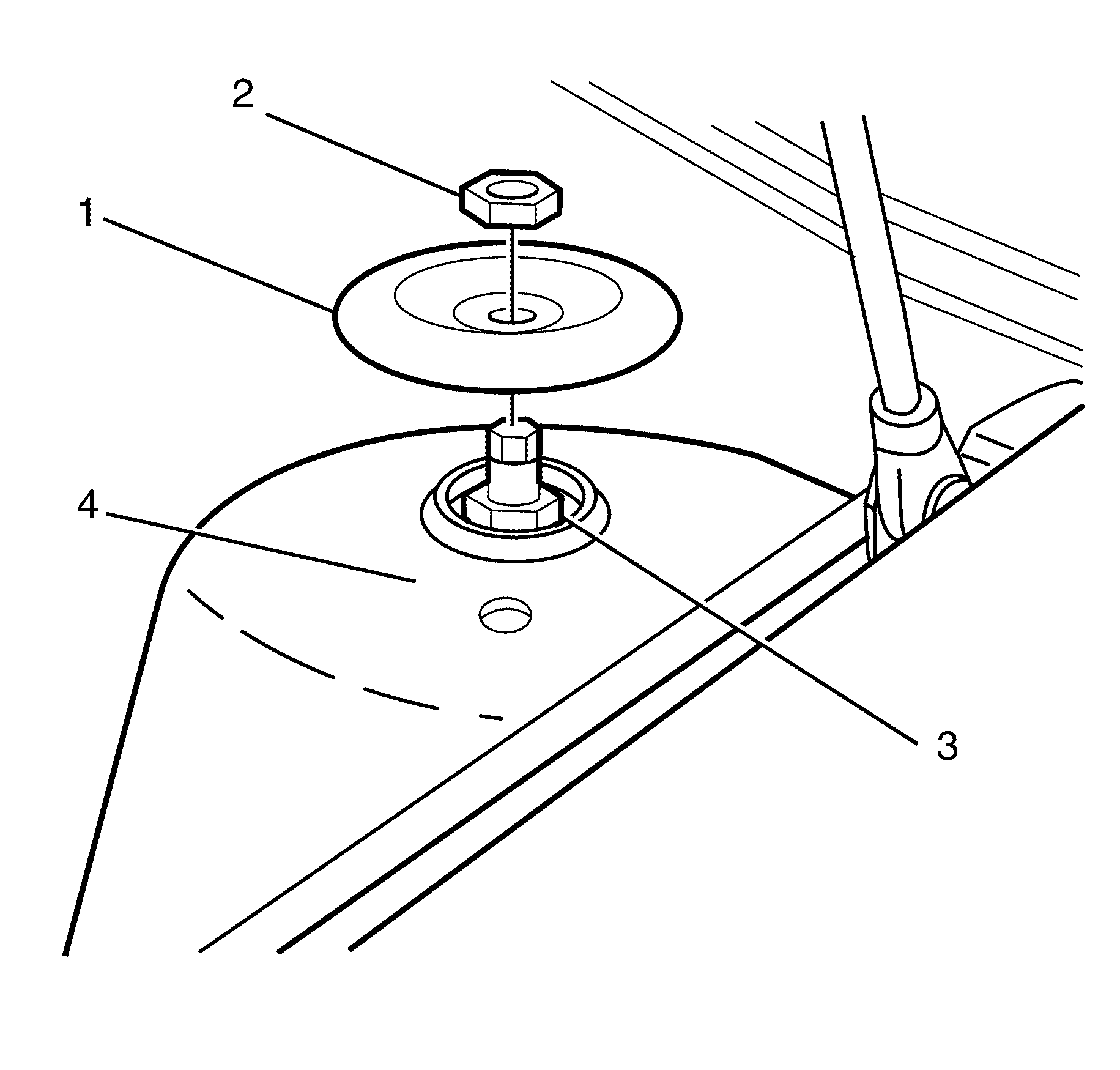
Important: The strut assembly to body retaining nut (2) must not be fully tightened at this stage.
Do not fully tighten at this stage.


Important: Pivot the hub and steering knuckle assembly sufficiently to line up the bolt holes in the steering knuckle and strut assembly.
Important: The strut assembly to steering knuckle retaining bolts (3) and nuts (1) must not be fully tightened at this stage.
Do not fully tighten at this stage.
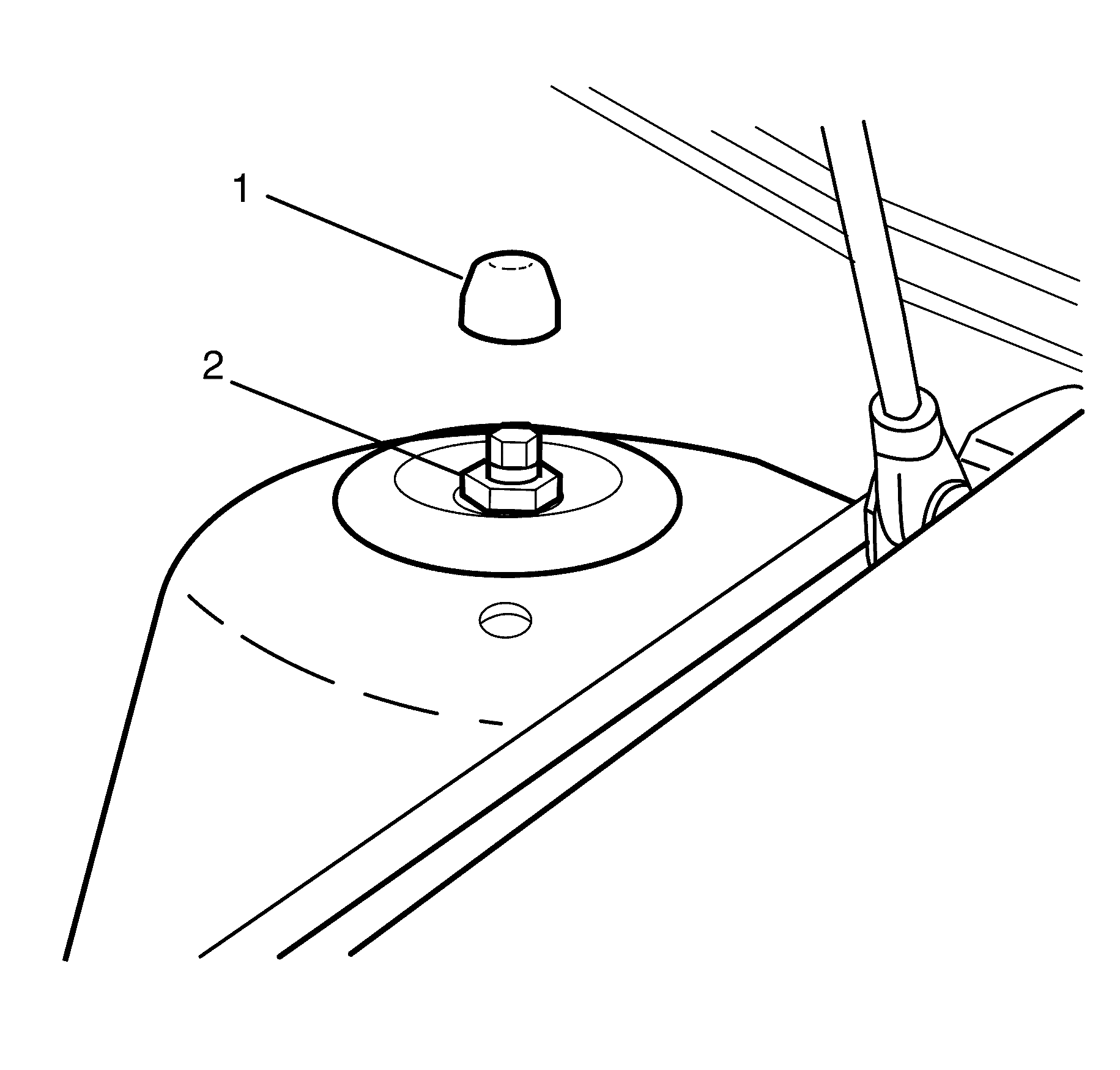
Tighten
Tighten the nut to 55 Nm (40 lb ft).


Tighten
Tighten the nut to 55 Nm (40 lb ft).
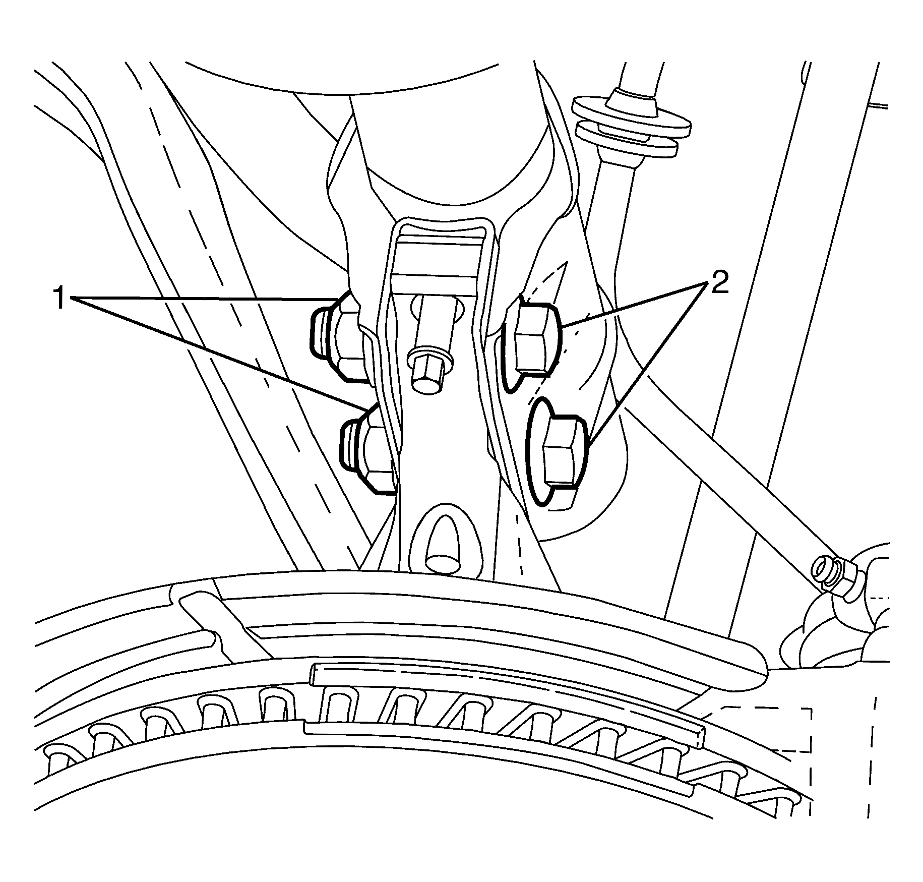
Tighten
Tighten the nuts a first pass to 85 Nm (63 lb ft).
Tighten
Tighten the nuts a second pass to 100 Nm
(74 lb ft).
Tighten
Tighten the nuts an additional 90 degrees.
