Engine Controls Connector End Views w/o CTF
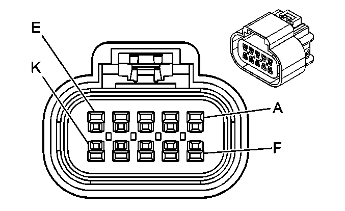
| Table 1: | Accelerator Pedal Position (APP) Sensor |
| Table 2: | Camshaft Position (CMP) Sensor |
| Table 3: | Crankshaft Position (CKP) Sensor |
| Table 4: | Engine Coolant Temperature (ECT) Sensor |
| Table 5: | Engine Oil Pressure (EOP) Sensor |
| Table 6: | ECM Relay |
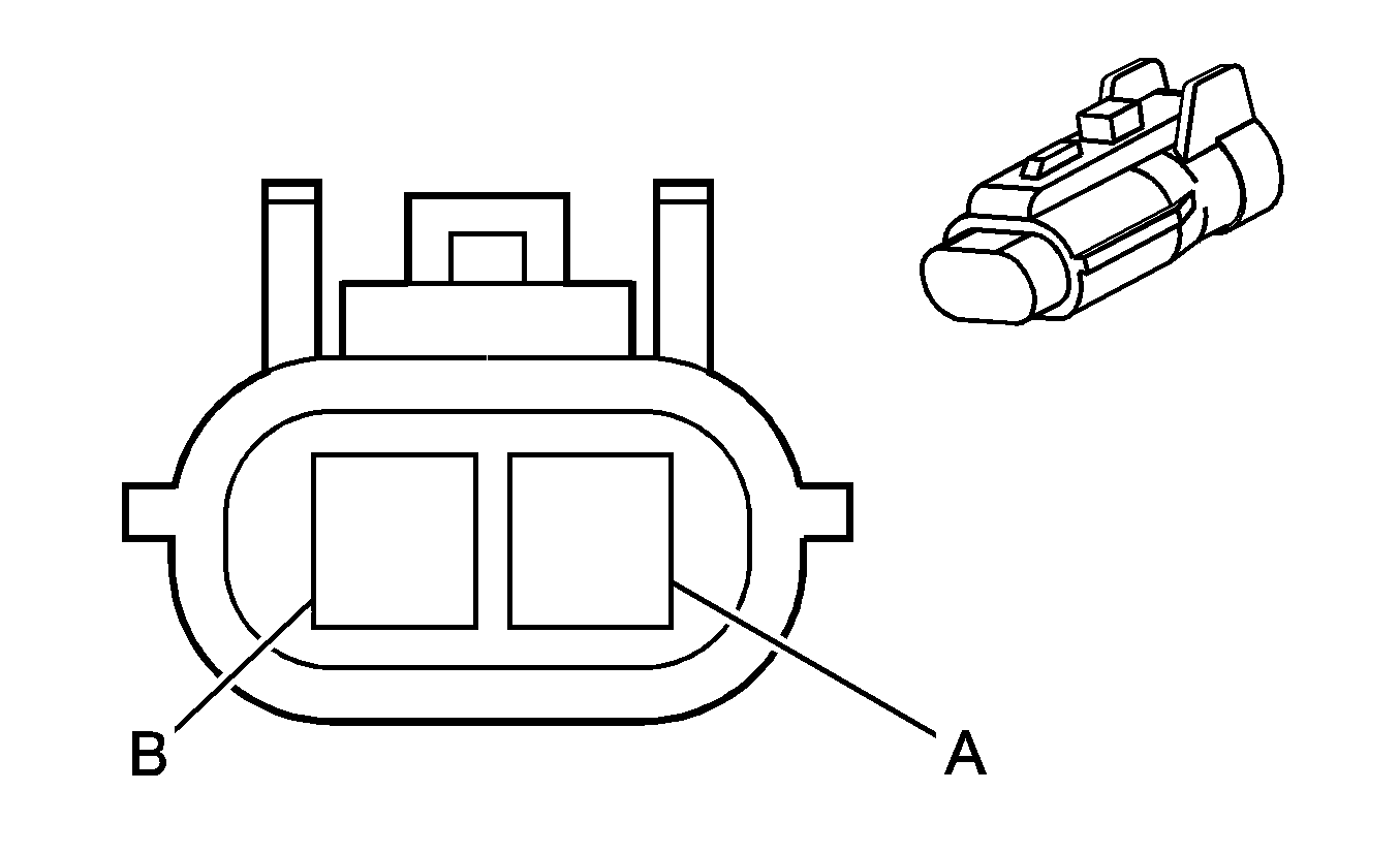
| Table 7: | Fuel Heater |
| Table 8: | Fuel Heater Relay |
| Table 9: | Fuel Rail Pressure (FRP) Sensor |
| Table 10: | Fuel Temperature Sensor |
| Table 11: | Glow Plug Relay C1 |
| Table 12: | Glow Plug Relay C2 |
| Table 13: | High Idle Switch (UF3) |
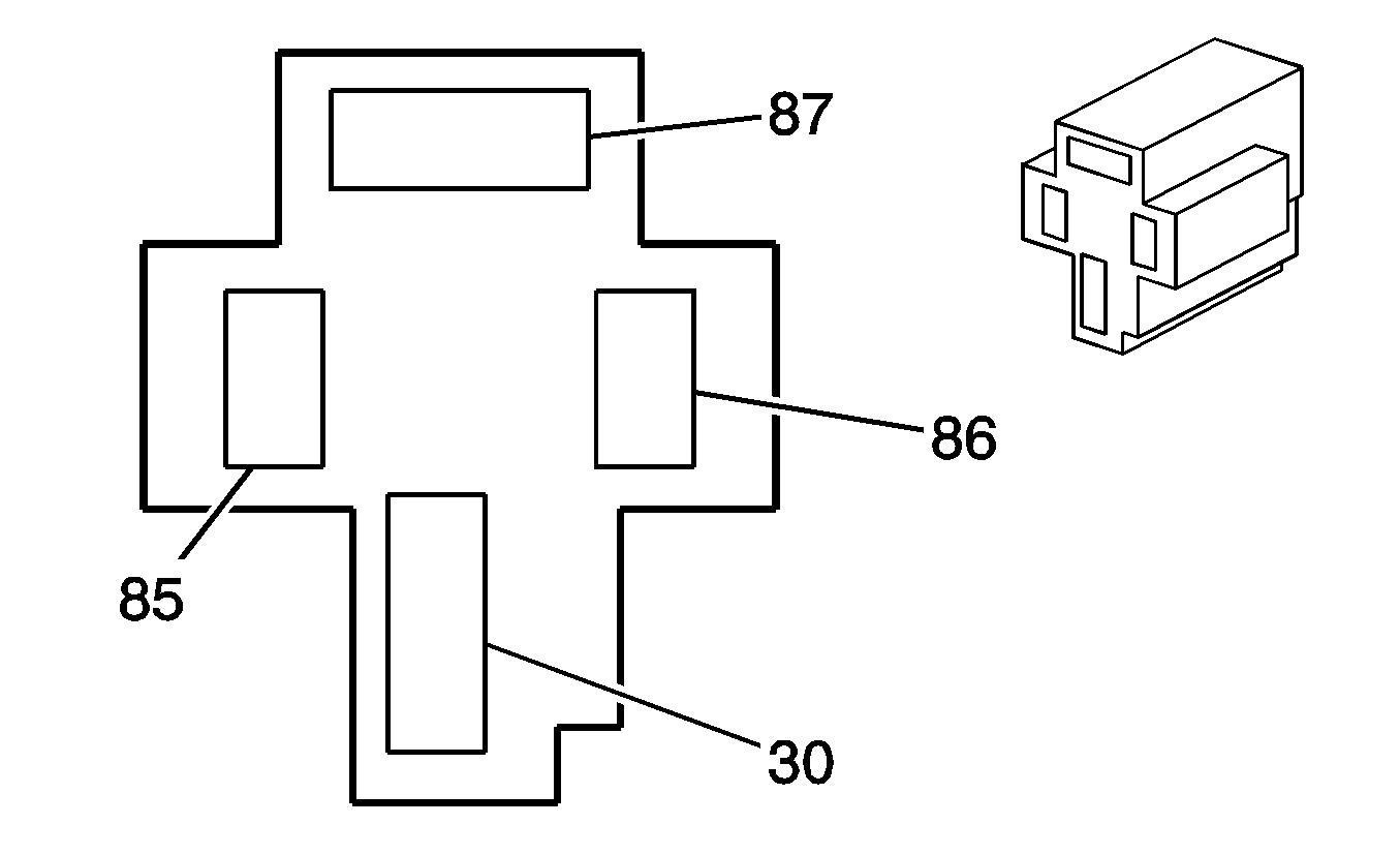
| Table 14: | Intake Air (IA) Heater Relay 1 |
| Table 15: | Intake Air (IA) Heater Relay 2 |
| Table 16: | Intake Air (IA) Heater Relay 3 |
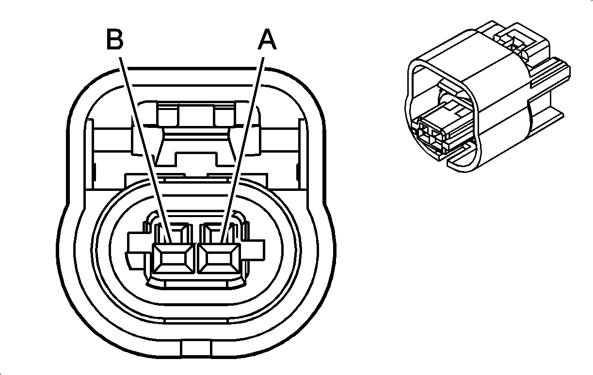
| Table 17: | Intake Air Temperature (IAT) Sensor |
| Table 18: | Manifold Absolute Pressure (MAP) Sensor |
| Table 19: | Pressure Control Valve 1 |
| Table 20: | Pressure Control Valve 2 |
| Table 21: | Pressure Control Valve Relay Diode |
| Table 22: | Pressure Control Valve Relay |
| |||||||
|---|---|---|---|---|---|---|---|
Connector Part Information |
| ||||||
Pin | Wire Color | Circuit No. | Function | ||||
A | D-GN | 262 | APP Sensor 3 Signal | ||||
B | YE/BK | 261 | 5-Volt Reference 3 | ||||
C | -- | -- | Not Used | ||||
D | WH/BK | 260 | 5-Volt Reference 1 | ||||
E | D-BU | 259 | APP Sensor 1 Signal | ||||
F | RD | 254 | Low Reference 3 | ||||
G | PU | 255 | Low Reference 2 | ||||
H | L-BU | 256 | APP Sensor 2 Signal | ||||
J | BK/WH | 257 | 5-Volt Reference 2 | ||||
K | TN | 258 | Low Reference 1 | ||||

| |||||||
|---|---|---|---|---|---|---|---|
Connector Part Information |
| ||||||
Pin | Wire Color | Circuit No. | Function | ||||
A | RD | 245 | CMP Sensor High | ||||
B | D-GN | 246 | CMP Sensor Low | ||||

| |||||||
|---|---|---|---|---|---|---|---|
Connector Part Information |
| ||||||
Pin | Wire Color | Circuit No. | Function | ||||
A | WH | 241 | CKP Sensor High | ||||
B | BK | 242 | CKP Sensor Low | ||||

| |||||||
|---|---|---|---|---|---|---|---|
Connector Part Information |
| ||||||
Pin | Wire Color | Circuit No. | Function | ||||
A | BK | 224 | Low Reference | ||||
B | -- | -- | Not Used | ||||
C | D-GN | 225 | Coolant Temperature Signal | ||||

| |||||||
|---|---|---|---|---|---|---|---|
Connector Part Information |
| ||||||
Pin | Wire Color | Circuit No | Function | ||||
1 | BK | 207 | Low Reference | ||||
2 | BN/WH | 206 | Oil Pressure Sensor Signal | ||||
3 | GN/RD | 205 | 5-Volt Reference | ||||

| |||||||
|---|---|---|---|---|---|---|---|
Connector Part Information |
| ||||||
Pin | Wire Color | Circuit No. | Function | ||||
30 | OG | 1 | Ignition 1 Voltage | ||||
85 | OG | 3 | Ignition 1 Voltage | ||||
86 | D-BU | 17 | ECM Voltage Supply | ||||
87 | RD/WH | 15 | Glow Plug Relay Coil Supply Voltage/Intake Air Heater Relay 3 Coil and Supply Voltage | ||||
87A | -- | -- | Not Used | ||||
| |||||||
|---|---|---|---|---|---|---|---|
Connector Part Information |
| ||||||
Pin | Wire Color | Circuit No. | Function | ||||
A | PK | 213 | Fuel Heater Supply Voltage | ||||
B | BK | 218 | Ground | ||||

| |||||||
|---|---|---|---|---|---|---|---|
Connector Part Information |
| ||||||
Pin | Wire Color | Circuit No. | Function | ||||
30 | OG | 9 | Battery Positive Voltage | ||||
85 | PK | 7 | Ignition 1 Voltage | ||||
86 | BK | 13 | Ground | ||||
87 | PK | 14 | Fuel Heater Supply Voltage | ||||
87A | -- | -- | Not Used | ||||

| |||||||
|---|---|---|---|---|---|---|---|
Connector Part Information |
| ||||||
Pin | Wire Color | Circuit No. | Function | ||||
1 | BK | 255 | Low Reference | ||||
2 | RD | 254 | FRP Sensor Signal | ||||
3 | WH | 253 | 5-Volt Reference | ||||

| |||||||
|---|---|---|---|---|---|---|---|
Connector Part Information |
| ||||||
Pin | Wire Color | Circuit No. | Function | ||||
A | BK | 228 | Low Reference | ||||
B | YE | 226 | Fuel Temperature Sensor Signal | ||||

| |||||||
|---|---|---|---|---|---|---|---|
Connector Part Information |
| ||||||
Pin | Wire Color | Circuit No. | Function | ||||
A | YE | 44 | Glow Plug Relay Control | ||||
B | RD/WH | 42 | ECM Voltage Supply | ||||

| |||||||
|---|---|---|---|---|---|---|---|
Connector Part Information |
| ||||||
Pin | Wire Color | Circuit No. | Function | ||||
A | RD | 45 | Battery Positive Voltage | ||||
B | RD/BK | 46 | Glow Plug Supply Voltage - Bank 1 | ||||

| |||||||
|---|---|---|---|---|---|---|---|
Connector Part Information |
| ||||||
Pin | Wire Color | Circuit No. | Function | ||||
1 | BK | 102 | Ground | ||||
2 | D-GN | 101 | High Idle Switch Signal | ||||
3 | PK | 103 | Ignition 1 Voltage | ||||
4 | RD | 104 | High Idle Indicator Control | ||||
5 | BK/RD | 106 | Illumination Dimming Control | ||||
6 | BK | 105 | Ground | ||||
| |||||||
|---|---|---|---|---|---|---|---|
Connector Part Information |
| ||||||
Pin | Wire Color | Circuit No. | Function | ||||
30 | BK/WH | 119 | Intake Air Heater Voltage | ||||
85 | BN | 125 | Intake Air Heater Relay Coil Supply Voltage | ||||
86 | BK | 127 | Ground | ||||
87 | RD | 116 | Battery Positive Voltage | ||||

| |||||||
|---|---|---|---|---|---|---|---|
Connector Part Information |
| ||||||
Pin | Wire Color | Circuit No. | Function | ||||
30 | BK/RD | 120 | Intake Air Heater Voltage | ||||
85 | BN | 126 | Intake Air Heater Relay Coil Supply Voltage | ||||
86 | BK | 128 | Ground | ||||
87 | RD | 118 | Battery Positive Voltage | ||||

| |||||||
|---|---|---|---|---|---|---|---|
Connector Part Information |
| ||||||
Pin | Wire Color | Circuit No. | Function | ||||
30 | RD/WH | 31 | Intake Air Heater Relay Supply Voltage | ||||
85 | OG | 32 | Intake Air Heater Relay Coil Supply Voltage | ||||
86 | D-BU | 17 | Intake Air Heater Relay Control | ||||
87 | RD/WH | 15 | Intake Air Heater Supply Voltage | ||||
87A | -- | -- | Not Used | ||||
| |||||||
|---|---|---|---|---|---|---|---|
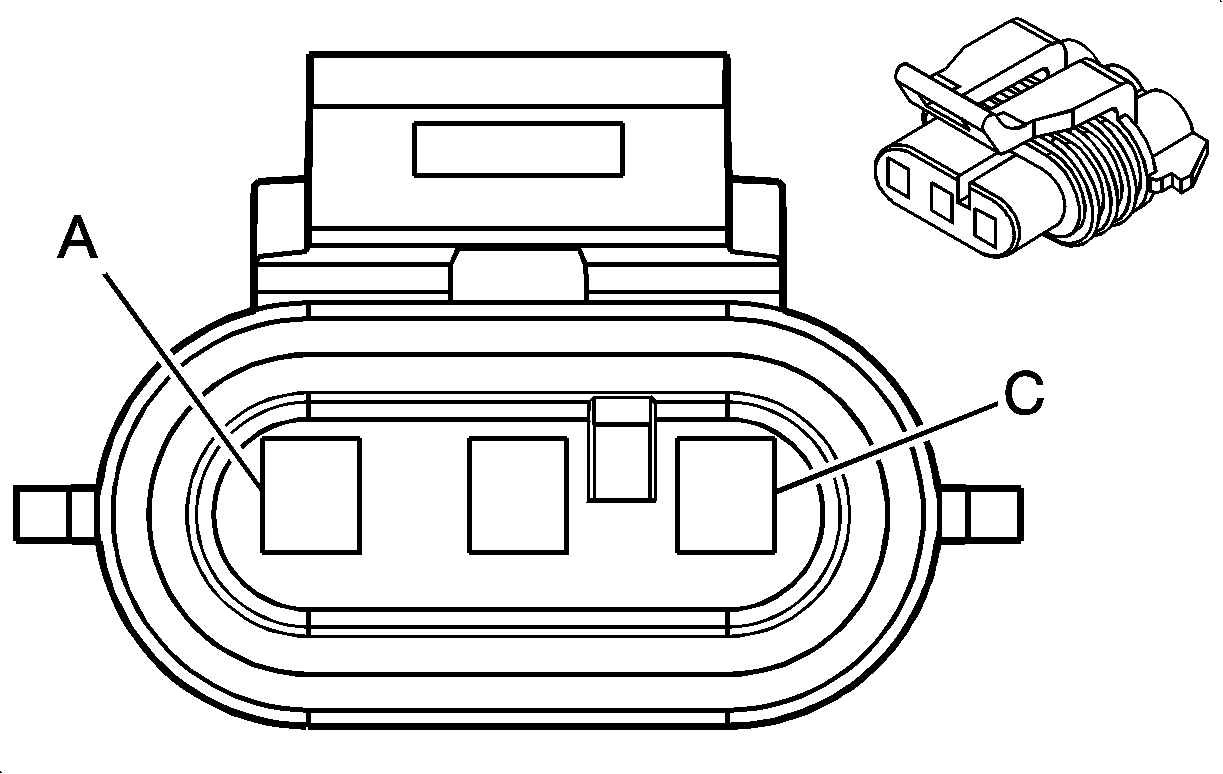
Connector Part Information |
| ||||||
Pin | Wire Color | Circuit No. | Function | ||||
A | BK | 234 | Low Reference | ||||
B | D-GN/WH | 233 | IAT Sensor Signal | ||||
| |||||||
|---|---|---|---|---|---|---|---|
Connector Part Information |
| ||||||
Pin | Wire Color | Circuit No. | Function | ||||
A | BK | 251 | Low Reference | ||||
B | RD | 250 | MAP Sensor Signal | ||||
C | OG/BK | 251 | 5-Volt Reference | ||||

| |||||||
|---|---|---|---|---|---|---|---|
Connector Part Information |
| ||||||
Pin | Wire Color | Circuit No. | Function | ||||
A | D-GN | 204 | Pressure Control Valve Relay Voltage | ||||
B | BN/WH | 260 | Pressure Control Valve 1 Control | ||||

| |||||||
|---|---|---|---|---|---|---|---|
Connector Part Information |
| ||||||
Pin | Wire Color | Circuit No. | Function | ||||
A | D-GN | 217 | Pressure Control Valve Relay Voltage | ||||
B | D-BU | 260 | Pressure Control Valve 2 Control | ||||

| |||||||
|---|---|---|---|---|---|---|---|
Connector Part Information |
| ||||||
Pin | Wire Color | Circuit No. | Function | ||||
A | BK/WH | 11 | Ground | ||||
B | BK | 12 | Ground | ||||

| |||||||
|---|---|---|---|---|---|---|---|
Connector Part Information |
| ||||||
Pin | Wire Color | Circuit No. | Function | ||||
30 | OG | 2 | Ignition 1 Voltage | ||||
85 | PK | 6 | Ignition 1 Voltage | ||||
86 | BN/WH | 11 | Ground | ||||
87 | RD/WH | 15 | Pressure Control Valve Supply Voltage | ||||
87A | -- | -- | Not Used | ||||
Engine Controls Connector End Views CTF
| Table 1: | Accelerator Pedal Position (APP) Sensor |
| Table 2: | Camshaft Position (CMP) Sensor |
| Table 3: | Crankshaft Position (CKP) Sensor |
| Table 4: | Engine Coolant Temperature (ECT) Sensor |
| Table 5: | Exhaust Gas Recirculation (EGR) Valve |
| Table 6: | Fuel Heater |
| Table 7: | Fuel Heater Relay |
| Table 8: | Fuel Rail Pressure (FRP) Sensor |
| Table 9: | Fuel Temperature Sensor |
| Table 10: | Glow Plug Relay C1 |
| Table 11: | Glow Plug Relay C2 |
| Table 12: | High Idle Switch (UF3) |
| Table 13: | Manifold Absolute Pressure (MAP) Sensor |
| Table 14: | Mass Air Flow (MAF)/Intake Air Temperature (IAT) Sensor |
| Table 15: | Suction Control Valve (SCV) |
| Table 16: | Turbocharger Vane Position (TVP) Control Solenoid Valve |
| Table 17: | Turbocharger Vane Position (TVP) Sensor |

| |||||||
|---|---|---|---|---|---|---|---|
Connector Part Information |
| ||||||
Pin | Wire Color | Circuit No. | Function | ||||
A | D-GN | CF18 | APP Sensor 3 Signal | ||||
B | YE/BK | CF17 | 5-Volt Reference | ||||
C | -- | -- | Not Used | ||||
D | WH/BK | CF11 | 5-Volt Reference | ||||
E | D-BU | CF12 | APP Sensor 1 Signal | ||||
F | GY | CF19 | Low Reference | ||||
G | PU | CF16 | Low Reference | ||||
H | L-BU | CF15 | APP Sensor 2 Signal | ||||
J | BN/WH | CF14 | 5-Volt Reference | ||||
K | TN | CF13 | Low Reference | ||||

| |||||||
|---|---|---|---|---|---|---|---|
Connector Part Information |
| ||||||
Pin | Wire Color | Circuit No. | Function | ||||
A | RD | B51 | 5-Volt Reference | ||||
B | WH | B30 | CMP Sensor Signal | ||||
C | BK | B18 | Low Reference | ||||

| |||||||
|---|---|---|---|---|---|---|---|
Connector Part Information |
| ||||||
Pin | Wire Color | Circuit No. | Function | ||||
A | WH | B31 | CKP Sensor High | ||||
B | BK | B32 | CKP Sensor Low | ||||

| |||||||
|---|---|---|---|---|---|---|---|
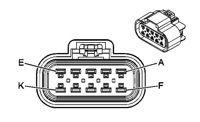
Connector Part Information |
| ||||||
Pin | Wire Color | Circuit No. | Function | ||||
A | BK/YE | IZ01 | Low Reference | ||||
B | RD | B42A | Fuel Temperature Sensor 2 Signal | ||||
C | D-BU/WH | B35A | Coolant Temperature Signal | ||||
| |||||||
|---|---|---|---|---|---|---|---|
Connector Part Information |
| ||||||
Pin | Wire Color | Circuit No. | Function | ||||
A | D-BU/RD | B38 | U Motor Position | ||||
B | WH/RD | B39 | V Motor Position | ||||
C | -- | -- | Not Available | ||||
D | YE/RD | B40 | W Motor Position | ||||
E | WH | B49 | 5-Volt Reference | ||||
F | BK/WH | B7 | U Motor Signal | ||||
G | D-GN | B8 | V Motor Signal | ||||
H | -- | -- | Not Available | ||||
J | RD/YE | B9 | W Motor Signal | ||||
K | WH/BK | B17 | Low Reference | ||||

| |||||||
|---|---|---|---|---|---|---|---|
Connector Part Information |
| ||||||
Pin | Wire Color | Circuit No. | Function | ||||
A | PK | IC35 | Fuel Heater Supply Voltage | ||||
B | BK | IC36 | Ground | ||||

| |||||||
|---|---|---|---|---|---|---|---|
Connector Part Information |
| ||||||
Pin | Wire Color | Circuit No. | Function | ||||
30 | OG | DF71 | Battery Positive Voltage | ||||
85 | PK | DF73 | Ignition 1 Voltage | ||||
86 | BK | CU18 | Ground | ||||
87 | PK | DF72 | Fuel Heater Supply Voltage | ||||
87A | -- | -- | Not Used | ||||

| |||||||
|---|---|---|---|---|---|---|---|
Connector Part Information |
| ||||||
Pin | Wire Color | Circuit No. | Function | ||||
1 | BK | B13 | Low Reference | ||||
2 | WH | B25 | FRP Sensor Signal | ||||
3 | RD | B47 | 5-Volt Reference | ||||

| |||||||
|---|---|---|---|---|---|---|---|
Connector Part Information |
| ||||||
Pin | Wire Color | Circuit No. | Function | ||||
A | BK/YE | IZ02 | Low Reference | ||||
B | YE | B41 | Fuel Temperature Sensor Signal | ||||

| |||||||
|---|---|---|---|---|---|---|---|
Connector Part Information |
| ||||||
Pin | Wire Color | Circuit No. | Function | ||||
A | YE | HB04 | Glow Plug Relay Control | ||||
B | RD/WH | HB03 | ECM Voltage Supply | ||||

| |||||||
|---|---|---|---|---|---|---|---|
Connector Part Information |
| ||||||
Pin | Wire Color | Circuit No. | Function | ||||
A | RD | HB01 | Battery Positive Voltage | ||||
B | RD/BK | HB02 | Glow Plug Supply Voltage - Bank 1 | ||||

| |||||||
|---|---|---|---|---|---|---|---|
Connector Part Information |
| ||||||
Pin | Wire Color | Circuit No. | Function | ||||
1 | BK | CU01 | Ground | ||||
2 | D-GN | CF24 | High Idle Switch Signal | ||||
3 | PK | CF25 | Ignition 1 Voltage | ||||
4 | RD | CF28 | High Idle Indicator Control | ||||
5 | BK/RD | CF27 | Illumination Dimming Control | ||||
6 | BK | CU02 | Ground | ||||

| |||||||
|---|---|---|---|---|---|---|---|
Connector Part Information |
| ||||||
Pin | Wire Color | Circuit No. | Function | ||||
A | BK | B12 | Low Reference | ||||
B | WH | B24 | MAP Sensor Signal | ||||
C | RD | B46 | 5-Volt Reference | ||||

| |||||||
|---|---|---|---|---|---|---|---|
Connector Part Information |
| ||||||
Pin | Wire Color | Circuit No. | Function | ||||
1 | RD | IC01 | Ignition 1 Voltage | ||||
2 | BK | B15 | Low Reference | ||||
3 | WH | B28 | MAF Sensor Signal | ||||
4 | D-GN/WH | B37 | IAT Sensor Signal | ||||
5 | BK/YE | IZ04 | Low Reference | ||||

| |||||||
|---|---|---|---|---|---|---|---|
Connector Part Information |
| ||||||
Pin | Wire Color | Circuit No. | Function | ||||
A | RD | B20 | SCV Low Signal | ||||
B | WH | B33 | SCV High Signal | ||||

| |||||||
|---|---|---|---|---|---|---|---|
Connector Part Information |
| ||||||
Pin | Wire Color | Circuit No. | Function | ||||
A | RD | IC02 | Ignition 1 Voltage | ||||
B | BK | B1 | TVP Control Solenoid Valve Control | ||||

| |||||||
|---|---|---|---|---|---|---|---|
Connector Part Information |
| ||||||
Pin | Wire Color | Circuit No. | Function | ||||
1 | RD | B50 | 5-Volt Reverence | ||||
2 | BK | B16 | Low Reference | ||||
3 | WH | B29 | TVP Sensor Signal | ||||
4 | -- | -- | Not Used | ||||
