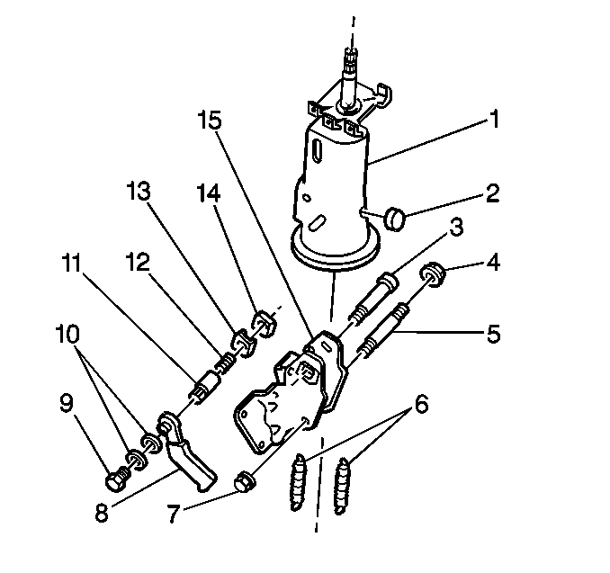
Removal Procedure

- Remove the upper steering shaft assembly. Refer
to
Upper Steering Shaft Assembly Replacement
.
- Remove the following components:
- Remove the following components:
| 3.1. | The tilt lever bolt (3) |
| 3.4. | The tilt shoe holder (13) |
Installation Procedure

- Position the tilt shoe in the tilt shoe holder
in order for the teeth of the shoe to align with the teeth of the steering
column mounting bracket.
- Install the following components:
| 2.1. | The tilt lever bolt (3) |
| 2.2. | The tilt shoe holder (13) |
| | Important: To ensure that the tilt lever will be in a locked position, it may be
necessary to reposition or turn the tilt lever bolt 90 degrees.
|
| 2.6. | Install the following components: |
| 2.10. | Install the upper steering shaft assembly. |


