Tire and Wheel Removal and Installation Disc Type - Single
Removal Procedure
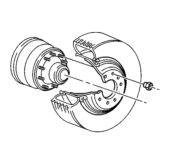
- Raise the vehicle until the tire clears the floor. Support the vehicle. Refer to Lifting and Jacking the Vehicle in General Information.
- Remove the wheel nuts.
- Remove the wheel from the hub.
- If the vehicle is equipped with hub-piloted wheels, use a brush in order to apply a thin coat of Frey Lube II® lubricant or equivalent to the hub pads only.
Caution: To avoid eye injury, use approved safety lenses, goggles, or face shield to prevent eye injury when deflating tires.
Important: When removing and demounting any tire and wheel assembly, deflate the tire by removing the valve core. Perform this procedure before removing the tire assembly from the vehicle.

Installation Procedure
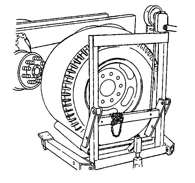
- If the vehicle is equipped with hub-piloted wheels, turn the hub so that a hub pad is at a 12 o'clock position.
- Install the wheel on the hub.
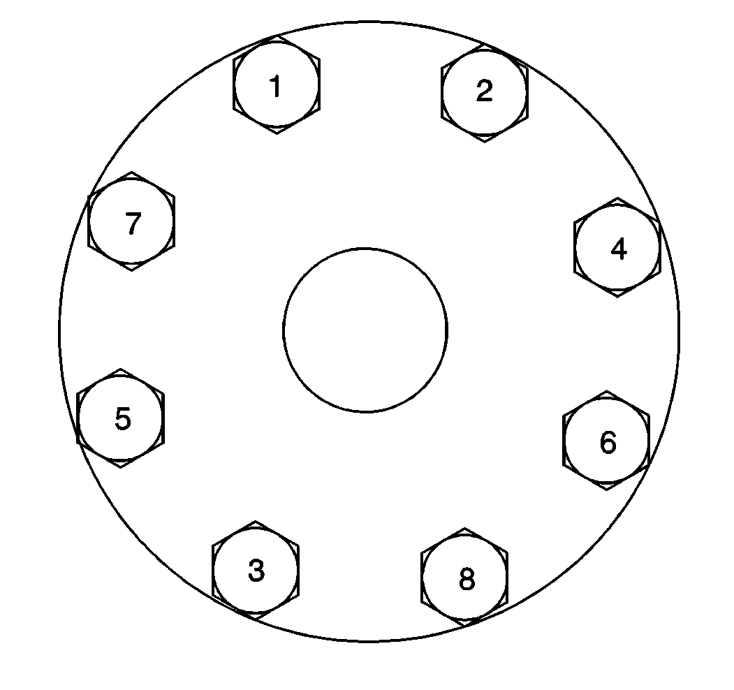
- For 8-hole aluminum or steel hub-piloted wheels, install the wheel nuts.
- Tighten the nuts to 100 N·m (74 lb ft) in the sequence shown.
- Tighten the nuts to 580 N·m (427 lb ft) in the sequence shown.
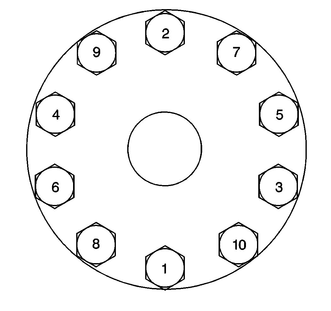
- For 10-hole aluminum or steel hub-piloted wheels, install the wheel nuts.
- Tighten the wheel nut to 225 N·m (166 lb ft) in the sequence shown.
- Tighten the wheel nut to 678 N·m (500 lb ft) in the sequence shown.
- For 10-hole aluminum stud-piloted wheels, install the wheel nuts.
- Tighten the wheel nut to 225 N·m (166 lb ft) in the sequence shown.
- Tighten the wheel nut to 644 N·m (475 lb ft) in the sequence shown.
- For 10-hole steel stud-piloted wheels, install the wheel nuts.
- Tighten the wheel nut to 225 N·m (166 lb ft) in the sequence shown.
- Tighten the wheel nut to 800 N·m (590 lb ft) in the sequence shown.


Notice: Use the correct fastener in the correct location. Replacement fasteners must be the correct part number for that application. Fasteners requiring replacement or fasteners requiring the use of thread locking compound or sealant are identified in the service procedure. Do not use paints, lubricants, or corrosion inhibitors on fasteners or fastener joint surfaces unless specified. These coatings affect fastener torque and joint clamping force and may damage the fastener. Use the correct tightening sequence and specifications when installing fasteners in order to avoid damage to parts and systems.
Important: Tighten the wheel nuts progressively using the first specification; then tighten the nuts using the second specification.
Tighten
Important: Tighten the wheel nuts progressively using the first specification; then tighten the nuts using the second specification.
Tighten
Tighten
Tighten
Tire and Wheel Removal and Installation Disc Type - Dual
Removal Procedure
- Break the wheel nuts loose.
- Raise and support the vehicle until the tire clears the floor. Refer to Lifting and Jacking the Vehicle in General Information.
- Remove the wheel nuts.
- Remove the wheel from the hub.
- If applicable, remove the stud nuts from the inner wheel.
- If applicable, remove the inner wheel from the hub.
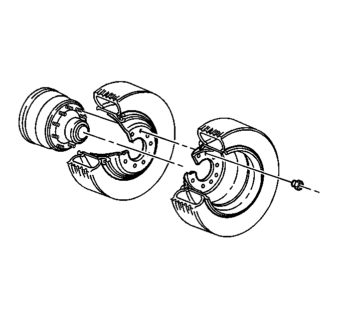
Caution: To avoid eye injury, use approved safety lenses, goggles, or face shield to prevent eye injury when deflating tires.
Notice: Wheel hub flanges, wheel studs, and stud nuts should be free of rust, lubricants, dirt, and finish color paint on all contact surfaces to ensure proper torque retention.
Important: When removing and demounting any tire and wheel assembly, deflate the tire by removing the valve core. Perform this procedure before removing the tire assembly from the vehicle.
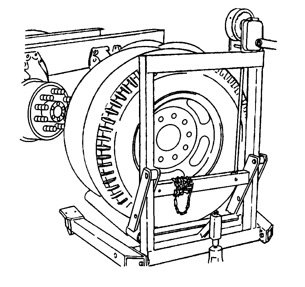
Installation Procedure
- If the vehicle is equipped with hub-piloted wheels, use a brush in order to apply a thin coat of Frey Lube II® lubricant or equivalent to the hub pads only.
- If the vehicle is equipped with hub-piloted wheels, turn the hub so that a hub pad is at a 12 o'clock position.
- Install the inner wheel if you removed the inner wheel.
- Torque the inner stud nuts.
- For 10-hole aluminum stud-piloted wheels, install the wheel nuts.
- Tighten the stud nuts to 225 N·m (166 lb ft) in the sequence shown.
- Tighten the stud nuts to 644 N·m (475 lb ft) in the sequence shown.
- For 10-hole steel stud-piloted wheels, install the wheel nuts.
- Tighten the stud nuts to 225 N·m (166 lb ft) in the sequence shown.
- Tighten the stud nuts to 800 N·m (590 lb ft) in the sequence shown.
- Install the outer wheel on the hub. Oppose the valve stems of both wheels by 180 degrees.
- For 8-hole wheels, install the wheel nuts.
- Tighten the stud nuts to 100 N·m (74 lb ft) in the sequence shown.
- Tighten the stud nuts to 550 N·m (400 lb ft) in the sequence shown.
- For 10-hole aluminum stud-piloted wheels, install the wheel nuts.
- Tighten the stud nuts to 225 N·m (166 lb ft) in the sequence shown.
- Tighten the stud nuts to 644 N·m (475 lb ft) in the sequence shown.
- For 10-hole steel stud-piloted wheels, install the wheel nuts.
- Tighten the stud nuts to 225 N·m (166 lb ft) in the sequence shown.
- Tighten the stud nuts to 800 N·m (590 lb ft) in the sequence shown.

Notice: Stud-piloted hubs' inner and outer stud nuts used on the right side of the vehicle have right-hand threads. Inner and outer nuts are stamped with the letter L to signify left or R to signify right. Care should be exercised to prevent trying to use the wrong thread nut as damage to the stud threads could occur.


Notice: Use the correct fastener in the correct location. Replacement fasteners must be the correct part number for that application. Fasteners requiring replacement or fasteners requiring the use of thread locking compound or sealant are identified in the service procedure. Do not use paints, lubricants, or corrosion inhibitors on fasteners or fastener joint surfaces unless specified. These coatings affect fastener torque and joint clamping force and may damage the fastener. Use the correct tightening sequence and specifications when installing fasteners in order to avoid damage to parts and systems.
Important: For vehicles equipped with stud-piloted wheels, tighten the wheel nuts progressively using the first specification; then tighten the nuts using the second specification.
Tighten
Tighten

Notice: Stud-piloted hubs' inner and outer stud nuts used on the right side of the vehicle have right-hand threads. Inner and outer nuts are stamped with the letter L to signify left or R to signify right. Care should be exercised to prevent trying to use the wrong thread nut as damage to the stud threads could occur.
Tighten
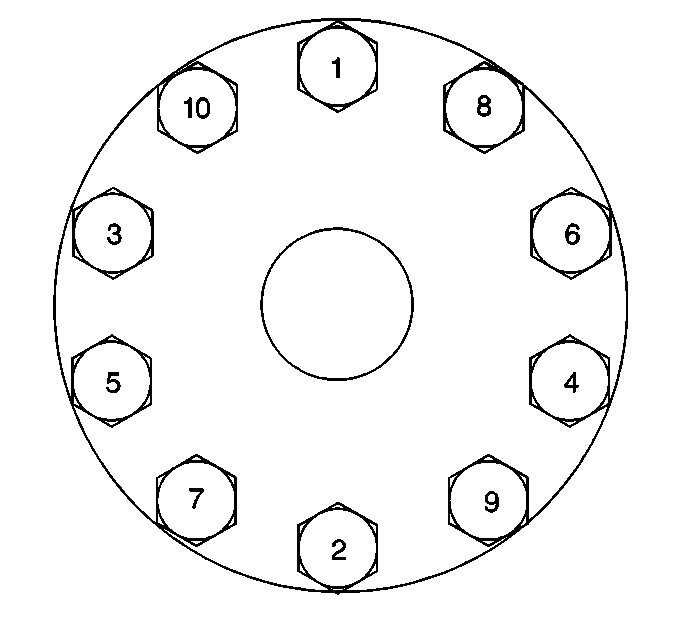
Notice: Stud-piloted hubs' inner and outer stud nuts used on the right side of the vehicle have right-hand threads. Inner and outer nuts are stamped with the letter L to signify left or R to signify right. Care should be exercised to prevent trying to use the wrong thread nut as damage to the stud threads could occur.
Tighten
