Removal Procedure
- Disable the SRS system. Refer to Disabling the SRS .
- Remove the steering column trim covers. Refer to Steering Column Trim Covers Replacement - On Vehicle in Steering Wheel and Column - Standard or Steering Column Trim Covers Replacement - On Vehicle in Steering Wheel and Column - Tilt.
- Remove the wire harness assembly (4) from the wire harness strap (5).
- Remove the 3 wire harness straps (3) from the wire harness assembly.
- Remove the wire harness strap (2) from the upper tilt head assembly (1).
- Remove the SRS steering wheel module coil retaining clip (1).
- Remove the SRS steering wheel module coil (2).
- Remove the wave washer (3) from the steering column upper shaft.

Caution: This vehicle is equipped with a Supplemental Restraint System (SRS).
Failure to follow the correct procedure could cause the following conditions:
• Air bag deployment • Personal injury • Unnecessary SRS system repairs • Refer to SRS Component Views in order to determine if you are
performing service on or near the SRS components or the SRS wiring. • If you are performing service on or near the SRS components or
the SRS wiring, disable the SRS system. Refer to Disabling the SRS System
in SRS.

Installation Procedure
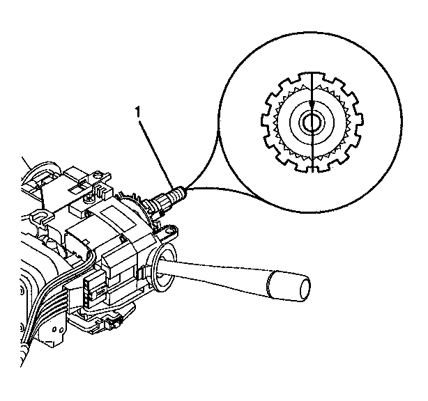
- Align the block tooth on the upper shaft to the 12 O'clock position.
- Install the wave washer (1) to the steering column upper shaft.
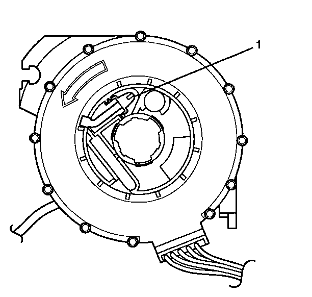
- Align the SRS steering wheel module coil (2) with the horn tower on the turn signal cancel cam (1)
- Install the pre-centered SRS steering wheel module coil (2) to the steering column upper shaft.
- Remove the centering tab (1) and discard.
- Install the SRS steering wheel module coil retaining ring. Verify that the ring (1) is firmly seated in the groove on the upper shaft (2).
- Install the wire harness assembly (4) into the wire strap (5).
- Install the wire harness strap (2) into the wire strap (1).
- Install wire harness straps (3) to the wire harness assembly.
- Install the steering column trim covers. Refer to Steering Column Trim Covers Replacement - On Vehicle in Steering Wheel and Column - Standard or Steering Column Trim Covers Replacement - On Vehicle in Steering Wheel and Column - Tilt.
- Enable the SRS system. Refer to Enabling the SRS .


Notice: Ensure all fasteners are securely seated before applying needed torque. Failure to do so may result in component damage or malfunctioning of steering column.

Important:
• Verify that the SRS steering wheel module coil is centered. • The SRS steering wheel module coil becomes uncentered under the
following conditions: - The steering column is separated from the steering gear and allowed
to rotate. - The centering spring is pushed down, letting the hub rotate while
the coil is removed from the steering column. • If the SRS steering wheel module coil becomes uncentered, refer
to the following procedures: - For the standard column, refer to
Inflatable Restraint Coil Centering - Off Vehicle
in Steering
Wheel and Column - Standard. - For the tilt column, refer to
Inflatable Restraint Coil Centering - Off Vehicle
in Steering Wheel and Column
- Tilt.


Notice: Gently pull on the lower coil assembly wire in order to remove any wire kinks inside of the column assembly. Verify that there are NO kinks or bends in the SIR coil assembly wire. If a kink or bend is present, interference may occur with the shaft lock mechanism. Turning the steering wheel may cut or damage the wire.

