Tools Required
J 41712 Oil Pressure Switch Socket
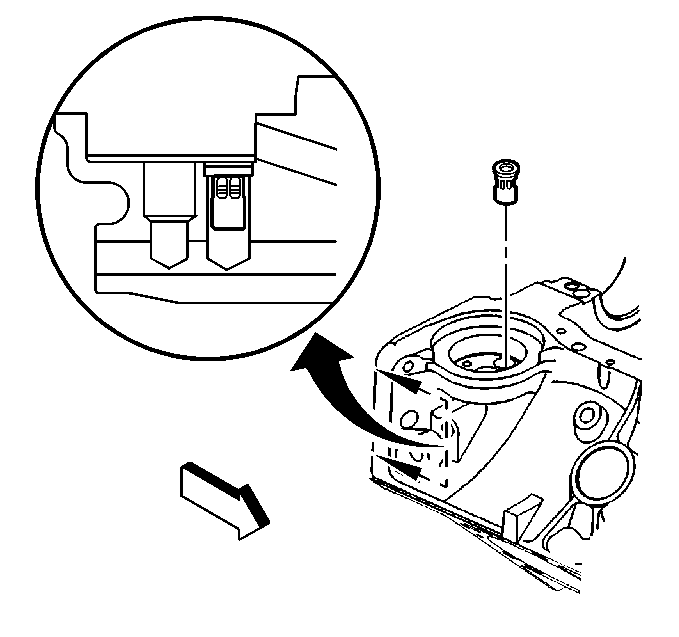
- Install a NEW oil filter bypass valve.
- Apply sealant to the outside diameter of the NEW front engine oil gallery plugs.
- Install the NEW front engine block oil gallery plugs.
- Apply threadlock to the outside diameter of the NEW engine block core hole plugs.
- Install the NEW engine block core hole plugs.
- Install the spring type S pin (crankshaft rear oil seal housing locator) (if required).
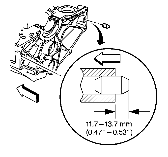
- Apply sealant to the outside diameter of the NEW expansion cup plug (balance rear bearing hole).
- Install the NEW expansion cup plug (balance shaft rear bearing hole).
- Apply sealant to the outside diameter of the NEW expansion cup plug (camshaft rear bearing hole).
- Install the NEW expansion cup plug (camshaft rear bearing hole).
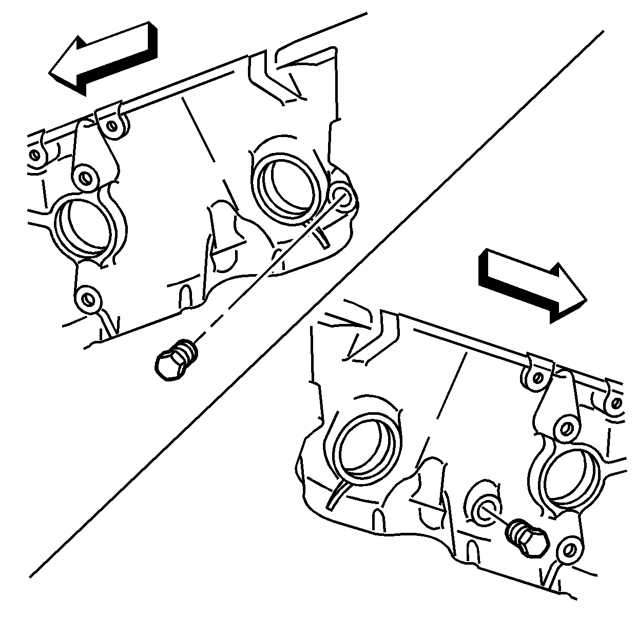
- Apply sealant to the threads of the engine block right rear oil gallery plug, the engine block left rear oil gallery plug, and the engine block left side oil gallery plug.
- Install the engine block right rear oil gallery plug, the engine block left rear oil gallery plug, and the engine block left side oil gallery plug.
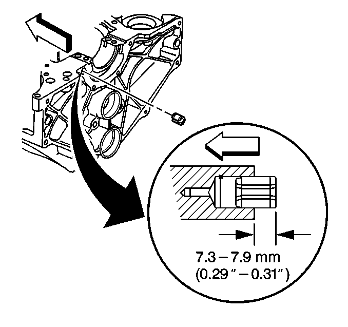
- Install the dowel straight pins (transmission locator) (if required).
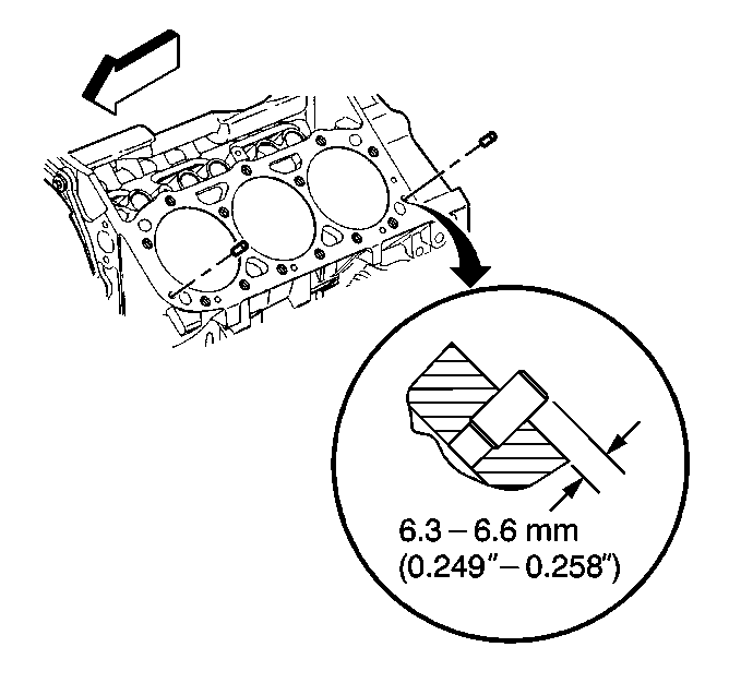
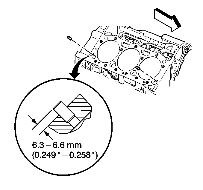
- Install the left side dowel pins (cylinder head locator) (if required).
- Install the right side dowel pins (cylinder head locator) (if required).
- Apply sealant to the threads of the engine block coolant drain hole plugs.
- Install the engine block coolant drain hole plugs.
- If reusing the engine oil pressure sensor fitting, apply sealant to the threads of the engine oil pressure sensor fitting.
- Install the engine oil pressure sensor fitting.
- Rotate the engine oil pressure sensor fitting clockwise to the proper position (1), 50 degrees from the centerline (2).
- If reusing the engine oil pressure gauge sensor, apply sealant to the threads of the engine oil pressure gauge sensor.
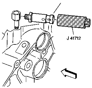
- Install the engine oil pressure gauge sensor using the J 41712 .
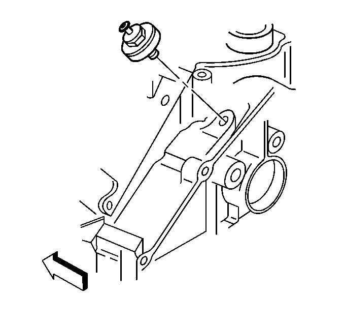
- Install the knock sensor.
Caution: Wear safety glasses in order to avoid eye damage.
| 1.1. | Install the oil filter bypass valve into the oil gallery bore until slightly below flush with the surface of the engine block. |
| 1.2. | Using a pointed punch, stake the engine block area around the oil filter bypass valve. |
Stake in 3 locations 120 degrees apart.
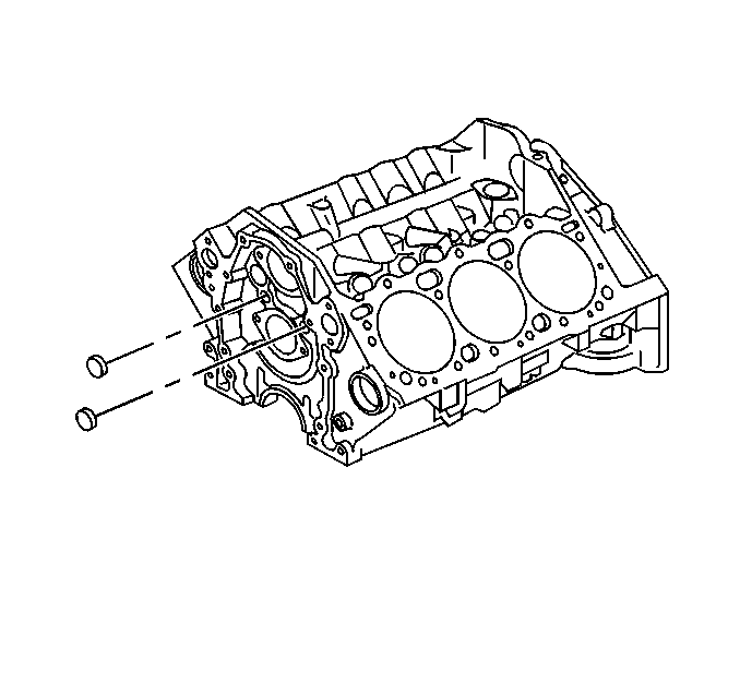
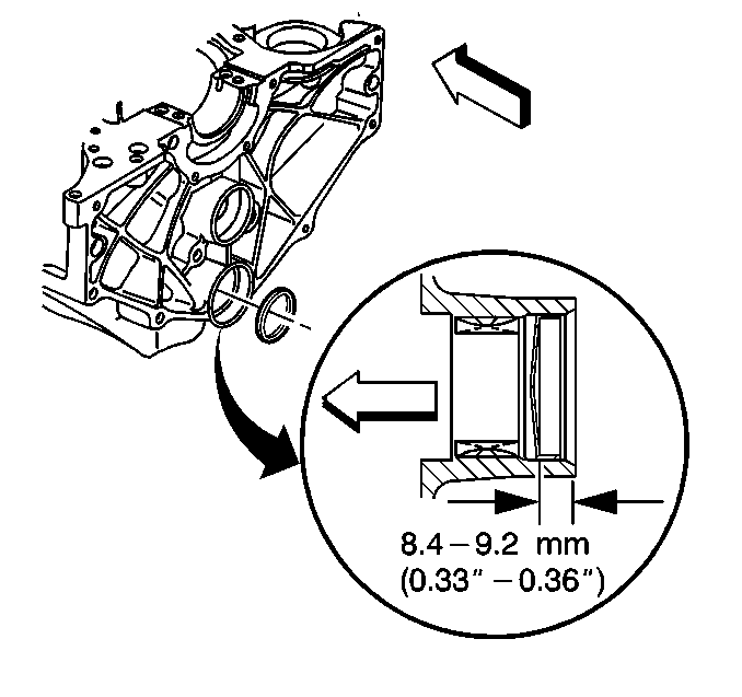
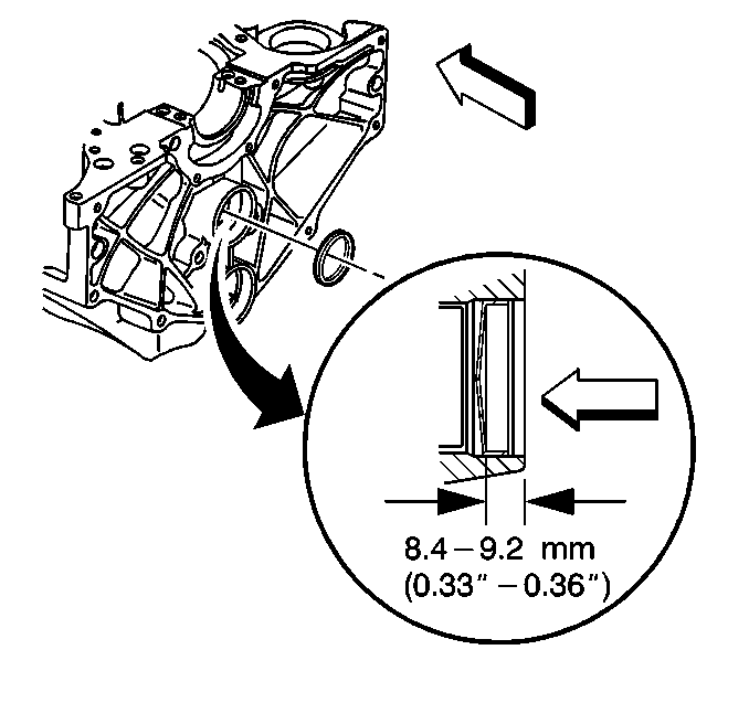
A properly installed front engine oil gallery plug must be installed slightly below flush with the front face of the engine block.
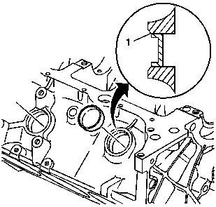
A properly installed engine block core hole plug must be installed flush with the bottom of the chamfer (1) of the engine block core hole.
Notice: Use the correct fastener in the correct location. Replacement fasteners must be the correct part number for that application. Fasteners requiring replacement or fasteners requiring the use of thread locking compound or sealant are identified in the service procedure. Do not use paints, lubricants, or corrosion inhibitors on fasteners or fastener joint surfaces unless specified. These coatings affect fastener torque and joint clamping force and may damage the fastener. Use the correct tightening sequence and specifications when installing fasteners in order to avoid damage to parts and systems.
Tighten
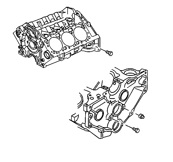
| • | Tighten the engine block left side oil gallery plug and the engine block right rear oil gallery plug to 20 N·m (15 lb ft). |
| • | Tighten the engine block left rear oil gallery plug 30 N·m (22 lb ft). |
Tighten
Tighten the engine block coolant hole plugs to 20 N·m (15 lb ft).
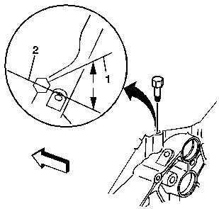
Important: Do not loosen the engine oil pressure fitting after the initial torque has been obtained.
Tighten
Tighten the engine oil pressure sensor fitting to 15 N·m
(11 lb ft).
Important: Do not rotate the engine oil pressure fitting clockwise more than 359 degrees after the initial torque has been obtained.
Tighten
Tighten the engine oil pressure gauge sensor to 30 N·m
(22 lb ft).
Tighten
Tighten the knock sensor to 20 N·m (15 lb ft).
Tools Required
J 41712 Oil Pressure Switch Socket
- Install a NEW oil filter bypass valve.
- Apply sealant GM P/N 12346004 (Canadian P/N 10953480) or equivalent, to the outside diameter of the NEW front engine oil gallery plugs.
- Install the NEW front engine block oil gallery plugs.
- Apply threadlock GM P/N 12345382 (Canadian P/N 10953489) or equivalent, to the outside diameter of the NEW engine block core hole plugs.
- Install the NEW engine block core hole plugs.
- Install the crankshaft rear oil seal housing locator spring type S pin, if required.
- Apply sealant GM P/N 12346004 (Canadian P/N 10953480) or equivalent, to the outside diameter of the NEW expansion cup plug.
- Install the NEW expansion cup plug into the balance shaft rear bearing hole.
- Apply sealant GM P/N 12346004 (Canadian P/N 10953480) or equivalent, to the outside diameter of the NEW expansion cup plug.
- Install the NEW expansion cup plug into the camshaft rear bearing hole.
- Apply sealant GM P/N 12346004 (Canadian P/N 10953480) or equivalent, to the threads of the engine block right rear oil gallery plug, the engine block left rear oil gallery plug, and the engine block left side oil gallery plug.
- Install the engine block right rear oil gallery plug, the engine block left rear oil gallery plug, and the engine block left side oil gallery plug.
- Install the transmission locator dowel straight pins, if required.
- Install the left side cylinder head locator dowel pins, if required.
- Install the right side cylinder head locator dowel pins, if required.
- Apply sealant GM P/N 12346004 (Canadian P/N 10953480) or equivalent, to the threads of the engine block coolant drain hole plugs.
- Install the engine block coolant drain hole plugs.
- If reusing the engine oil pressure sensor fitting, apply sealant GM P/N 12346004 (Canadian P/N 10953480) or equivalent, to the threads of the engine oil pressure sensor fitting.
- Install the engine oil pressure sensor fitting.
- Rotate the engine oil pressure sensor fitting clockwise to the proper position (1), 50 degrees from the centerline (2).
- If reusing the engine oil pressure gage sensor, apply sealant GM P/N 12346004, (Canadian P/N 10953480) or equivalent, to the threads of the engine oil pressure gage sensor.
- Install the engine oil pressure gage sensor using the J 41712 .
- Install the knock sensor (2).
- Install the knock sensor retaining bolt (1).

Caution: Wear safety glasses in order to avoid eye damage.
| 1.1. | Install the oil filter bypass valve into the oil gallery bore until slightly below flush with the surface of the engine block. |
| 1.2. | Using a pointed punch, stake the engine block area around the oil filter bypass valve. |
Stake in 3 locations 120 degrees apart.

A properly installed front engine oil gallery plug must be installed slightly below flush with the front face of the engine block.

A properly installed engine block core hole plug must be installed flush or below the bottom of the chamfer (1) of the engine block core hole.


Notice: Use the correct fastener in the correct location. Replacement fasteners must be the correct part number for that application. Fasteners requiring replacement or fasteners requiring the use of thread locking compound or sealant are identified in the service procedure. Do not use paints, lubricants, or corrosion inhibitors on fasteners or fastener joint surfaces unless specified. These coatings affect fastener torque and joint clamping force and may damage the fastener. Use the correct tightening sequence and specifications when installing fasteners in order to avoid damage to parts and systems.
Tighten
| • | Tighten the engine block left side oil gallery plug and the engine block right rear oil gallery plug to 20 N·m (15 lb ft). |
| • | Tighten the engine block left rear oil gallery plug to 30 N·m (22 lb ft). |


Tighten
Tighten the engine block coolant hole plugs to 20 N·m (15 lb ft).

Important: Do not loosen the engine oil pressure fitting after the initial torque has been obtained.
Tighten
Tighten the engine oil pressure sensor fitting to 15 N·m
(11 lb ft).
Important: Do not rotate the engine oil pressure fitting clockwise more than 359 degrees after the initial torque has been obtained.

Tighten
Tighten the engine oil pressure gage sensor to 30 N·m (22 lb ft).

Tighten
Tighten the knock sensor to 25 N·m (18 lb ft).
