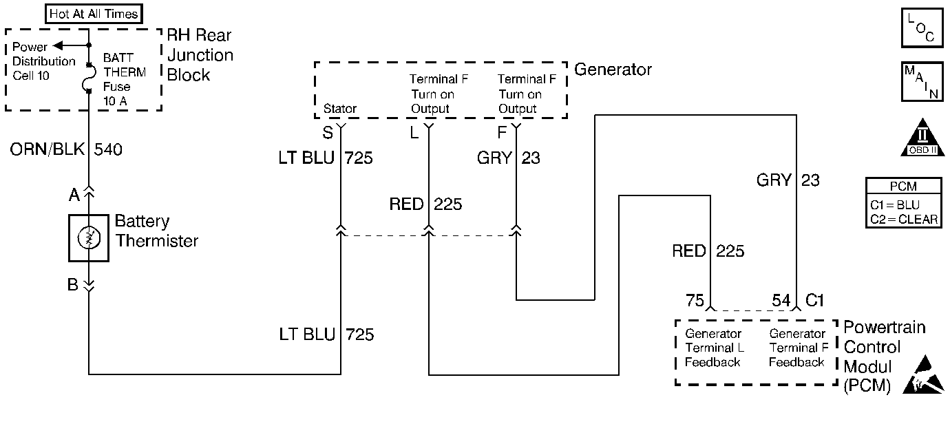
Circuit Description
The PCM monitors the voltage level on the L-terminal circuit while the generator is commanded ON and expects to see approximately B+. If the PCM monitors a low voltage level on CKT 225 at PCM connector C1 terminal 75 indicating that the generator is turned OFF, DTC P1637 is set.
Conditions for Running the DTC
Engine running.
Conditions for Setting the DTC
The state of the L-terminal feedback is indicating the generator is not charging, low input voltage, for 15 seconds.
Action Taken When the DTC Sets
PCM turns ON the low voltage warning lamp.
| • | The Malfunction Indicator Lamp (MIL) will not illuminate. |
| • | The PCM will command a message to be displayed. |
| • | The PCM may record operating conditions at the time the diagnostic fails. This information will be stored in the Failure Records. |
Conditions for Clearing the Message/DTC
| • | The PCM will turn the message OFF after one run and pass of the diagnostic test. |
| • | A History DTC will clear after forty consecutive warm-up cycles with no failures of any non-emission related diagnostic test. |
| • | A Last Test Failed (current) DTC will clear when the diagnostic runs and does not fail. |
| • | Use a scan tool to clear DTCs. |
| • | Interrupting PCM battery voltage may or may not clear DTCs. This practice is not recommended. Refer to Clearing Diagnostic Trouble Codes in Powertrain Control Module Description . |
Diagnostic Aids
DTC P1637 and a low battery charge may be caused by a generator fault. Such as a shorted output diode, malfunctioning regulator, open or shorted rotor, or open sense lead. Refer to Engine Electrical for further information and generator diagnosis. This DTC will not set if circuit 225 is shorted to voltage but may cause a parasitic load on the battery with the key OFF.
Test Description
Number(s) below refer to the step number(s) on the Diagnostic Table.
-
Checking if PCM/ wiring or generator/ S terminal wiring is at fault.
-
Checking if problem is S terminal circuit problem or generator problem.
Step | Action | Value(s) | Yes | No |
|---|---|---|---|---|
1 | Did you perform the Powertrain On-Board Diagnostic (OBD) System Check? | -- | Go to Step 2 | |
Is the voltage the same or more than the value specified? | 10 V | Go to Step 9 | Go to Step 3 | |
3 |
Is the resistance the same or more than the value specified? | 10K ohms | Go to Step 4 | Go to Step 5 |
4 | Measure resistance between generator harness connector terminal L and PCM connector C1 terminal 75. Is the resistance the same or less than the value specified? | 5 ohms | Go to Step 7 | Go to Step 6 |
5 | Repair short to ground in the L terminal circuit. Is the repair complete? | -- | -- | |
6 | Repair open/high resistance in the L terminal circuit. Is the repair complete? | -- | -- | |
7 | Check terminal contact at PCM connector C1 terminal 75. Was a terminal problem found and corrected? | -- | Go to Powertrain Control Module Diagnosis for Verify Repair | Go to Step 8 |
8 | Replace the PCM. Refer to Powertrain Control Module Replacement/Programming . Is the replacement complete? | -- | -- | |
Are the measured voltages within the value specified of each other? | 1.0 V | Go to Step 11 | Go to Step 10 | |
10 | Repair open or high resistance in the S terminal circuit or in the battery temperature sensor. Refer to Engine Electrical. Is the repair complete? | -- | -- | |
11 | Repair or replace generator. Refer to Engine Electrical. Is the repair complete? | -- | -- |
