Caution: This vehicle is equipped with Supplemental Inflatable Restraint (SIR).
Refer to the Cautions in the On-Vehicle Service and the SIR Component and
Wiring Location view in the Supplemental Inflatable (SIR) System before any
performing service on or around SIR components or wiring. Failure to follow
the Cautions could result in possible air bag deployment, personal injury,
or otherwise unneeded SIR system repairs.
Notice: Always use the correct fastener in the proper location. When you replace
a fastener, use ONLY the exact part number for that application.
The applicable service procedure will identify, where necessary, those
fasteners that must be replaced after removal; or those fasteners that require
the use of thread locking compound or thread sealant.
UNLESS OTHERWISE SPECIFIED, do not use supplemental coatings (paints,
greases, or other corrosion inhibitors) on threaded fasteners or fastener
joint interfaces. Generally, such coatings adversely affect the fastener torque
and the joint clamping force, and may damage the fastener.
When you install fasteners, use the correct tightening sequence and
specifications.
Following these instructions can help you avoid damage to parts and
systems.
Notice: Use the correct fastener in the correct location. Replacement fasteners
must be the correct part number for that application. Fasteners requiring
replacement or fasteners requiring the use of thread locking compound or sealant
are identified in the service procedure. Do not use paints, lubricants, or
corrosion inhibitors on fasteners or fastener joint surfaces unless specified.
These coatings affect fastener torque and joint clamping force and may damage
the fastener. Use the correct tightening sequence and specifications when
installing fasteners in order to avoid damage to parts and systems.
General Description
The fuel supply is stored in the fuel tank. An electric fuel pump, inside
the modular fuel sender assembly (inside the fuel tank) pumps fuel through
an in-line filter to the fuel injection system. The fuel pump is
designed to provide fuel at a pressure above the regulated pressure needed
by the fuel injectors. A fuel pressure regulator keeps fuel available
to the fuel injectors at a regulated pressure. Unused fuel is returned
to the fuel tank by a separate pipe. For further information on the
fuel injection system, refer to
Fuel Metering System Component Description
.
Unleaded fuel must be used with all gasoline engines for proper emission
control system operation. Using unleaded fuel will also decrease spark plug
fouling and extend engine oil life. Leaded fuel can damage the emission
control system, and its use can result in loss of emission warranty
coverage.
All vehicles with gasoline engines are equipped with an evaporative
emission system that minimizes the escape of fuel vapors to the atmosphere.
For information regarding this system, refer to
Evaporative Emission Control System Operation Description
.
On-Board Refueling Vapor Recovery System (ORVR)
The On-Board Refueling Vapor Recovery System (ORVR) is an on-board vehicle
system to recover fuel vapors during the vehicle re-fueling operation. The
flow of liquid fuel down to the fuel tank filler neck provides a liquid
seal. The purpose of (ORVR) is to prevent re-fueling vapor from exiting
the fuel tank filler neck.
The ORVR components include:
| • | Modular Fuel Sender (fuel tank pressure sensor located on modular
fuel sender cover) |
| • | Fuel Limiter Vent Valve (FLVV) |
| • | Pressure Vacuum Relief Valve |
| • | Vapor Recirculation Line |
The On-board Refueling Vapor Recovery System (ORVR) is an on-board vehicle
system designed to recover fuel vapors during the vehicle refueling operation.
The flow of liquid fuel down the filler neck provides a liquid seal
which prevents vapor from leaving the fuel system by transporting vapor
to the EVAP canister for use by the engine. Listed below are the ORVR
system components with a brief description of their operation:
| • | Fuel Tank - contains the modular fuel sender, fuel limiter vent
valve, and three rollover valves. |
| • | Fuel Filler Pipe - the pipe which carries fuel from the fuel nozzle
to the fuel tank. |
| • | EVAP Canister - the EVAP canister receives refueling vapor from
the fuel system, stores the vapor and releases the vapor to the engine upon
demand. |
| • | Vapor Lines - transports fuel vapor from the tank assembly to
the EVAP canister. |
| • | Check Valve - the check valve limits fuel "spit-back"
from the fuel tank during the refueling operation by allowing fuel flow only
into the fuel tank. This check valve is located at the bottom of the
fuel filler pipe. |
| • | Modular Fuel Sender Assembly - this assembly pumps fuel to the
engine from the fuel tank. |
| • | Fill Limiter Vent Valve (FLVV) - this valve acts as a shut-off
valve located in the fuel tank and has the following functions: |
| - | Controls the fuel tank fill level by closing the primary vent
from the fuel tank. |
| - | Prevents fuel from exiting the fuel tank via the vapor line to
the canister. |
| - | Provides fuel-spillage protection in the event of a vehicle rollover
by closing the vapor path from the tank to the EVAP canister. |
| • | Pressure/Vacuum Relief Valve - the pressure/vacuum relief valve
provides venting of excessive fuel tank pressure and vacuum. The valve is
located in the fuel filler neck on a plastic fuel tank. |
| • | Vapor Recirculation Line - The vapor recirculation line is used
to transport vapor from the fuel tank to the top of the fill pipe during
the refueling to reduce vapor loading to the Enhanced EVAP canister. |
| • | Variable Orifice Valve - The variable orifice valve regulates
the amount of vapor allowed to enter the vapor recirculation line. |
Enhanced EVAP System Operation
The basic Evaporative Emission (EVAP) Control System used on all vehicles
is the charcoal canister storage method. This method transfers fuel vapor
from the fuel tank to an activated carbon (charcoal) storage device canister
to hold the vapors when the vehicle is not operating. When the engine is
running, the fuel vapor is purged from the carbon element by intake air flow
and consumed in the normal combustion process.
The EVAP purge valve allows manifold vacuum to purge the canister. The
Powertrain Control Module (PCM) supplies a ground to energize the EVAP purge
valve (purge ON). The EVAP purge valve control is Pulse Width Modulated (PWM)
or turned ON and OFF several times a second.
The evaporative leak detection diagnostic strategy is based on applying
vacuum to the EVAP system and monitoring vacuum decay. The fuel level sensor
input to the PCM is used to determine if the fuel level in the tank is correct
to run the EVAP diagnostic tests. To insure sufficient volume in the fuel
tank to begin the various diagnostic tests, the fuel level must be between
15 percent and 85 percent. The PCM monitors system vacuum level via the fuel
tank pressure sensor input.
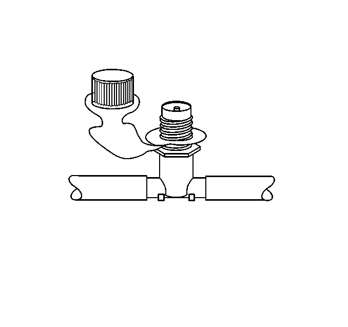
Enhanced Evaporative Emission (EVAP) Service Port

The enhanced EVAP service
port is located in the evaporative purge hose located between the purge solenoid
and the EVAP charcoal canister. The service port is identified by a
green colored cap. The port contains a schrader valve and fittings
to allow the connection of the J 41413, evaporative pressure/purge
diagnostic system. Refer to EVAP control system diagnosis for further
information and diagnosis of the Enhanced EVAP system.
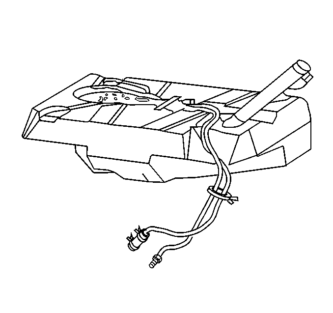
Fuel Tank

The fuel tank is used to store fuel for the vehicle. The tank is located
in the rear of the vehicle and is held in place by two straps that are attached
to the underbody. The fuel tank is made of plastic, and is coated internally
with a special corrosion inhibitor. Due to the internal coating of the
fuel tank, the fuel tank is not repairable. The fuel tank shape includes
a reservoir in order to maintain a constant supply of fuel around the
fuel pump strainer during low fuel conditions and aggressive vehicle
maneuvers.
The tank also contains a fuel vapor vent valve with roll-over protection.
The vent valve also features a two phase vent calibration which increases
fuel vapor flow to the canister when operating temperatures increase
the tank pressure beyond an established threshold.
The fuel tank contains 3 rollover valves that prevents fuel from entering
the fuel pipes in the event of a vehicle rollover. The rollover valves are
not repairable.
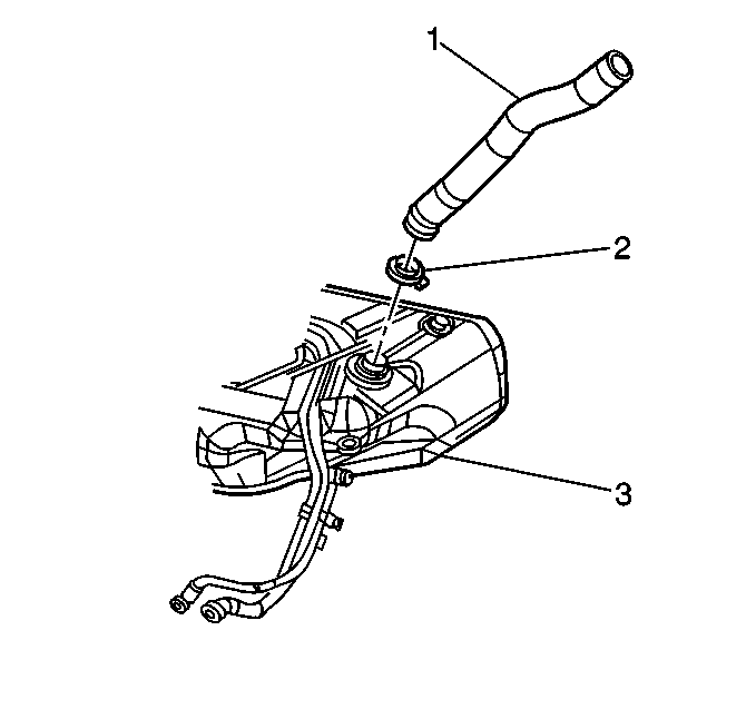
Fuel Tank Filler Pipe


